Article

Physicomechanical Nature of Acoustic Emission Preceding Wire Breakage during Wire Electrical Discharge Machining (WEDM) of Advanced Cutting Tool Materials

by
Sergey N. Grigoriev
1,
Petr M. Pivkin
1,2,3,4,*,
Mikhail P. Kozochkin
1,4,
Marina A. Volosova
1,
Anna A. Okunkova
1,
Artur N. Porvatov
1,
Alexander A. Zelensky
1 and
Alexey B. Nadykto
5,*
1
Department of High-Efficiency Processing Technologies, Moscow State University of Technology “STANKIN”, 127055 Moscow, Russia
2
Department of Cutting Tools and Machining Technologies, Moscow State University of Technology “STANKIN”, 127055 Moscow, Russia
3
Laboratory of Micromachining Technologies, Moscow State University of Technology “STANKIN”, 127055 Moscow, Russia
4
Center of Cognitive Technologies and Machine Vision, Moscow State University of Technology “STANKIN”, 127055 Moscow, Russia
5
Department of Applied Mathematics, Moscow State University of Technology “STANKIN”, 127055 Moscow, Russia
*
Authors to whom correspondence should be addressed.
Metals 2021, 11(11), 1865; https://doi.org/10.3390/met11111865
Submission received: 17 October 2021 / Revised: 12 November 2021 / Accepted: 15 November 2021 / Published: 19 November 2021

Abstract

:
The field of applied wire electrical discharge machining (WEDM) is rapidly expanding due to rapidly increasing demand for parts made of hard-to-machine materials. Hard alloys composed of WC, TiC and Co are advanced cutting materials widely used in industry due to the excellent combination of hardness and toughness, providing them obvious advantages over other cutting materials, such as cubic boron nitride, ceramics, diamond or high-speed steel. A rational choice of the WEDM modes is extremely important to ensure the dimensional quality of the manufactured cutting inserts, while roughness of the machined surface on the cutting edge is of great importance with regards to the application of wear-resistant coatings, which increases tool life. However, the stock control systems of CNC WEDM machines, which are based on assessment of electrical parameters such as amperage and voltage, are unable to timely detect conditions at which a threat of wire breakage appears and to prevent wire breakage by stopping the electrode feed and flushing out the interelectrode gap (IEG) when hard alloys with high heat resistance and low heat conductivity, such as WC, TiC and Co composites, are being machined, due to the inability to distinguish the working pulses and pulses that expend a part of their energy heating and removing electroerosion products contaminating the working zone. In this paper, the physicomechanical nature of the WEDM of hard alloy WC 88% + TiC 6% + Co 6% was investigated, and the possibility of using acoustic emission parameters for controlling WEDM stability and productivity were explored. Acoustic emission (AE) signals were recorded in octave bands with central frequencies of 1–3 and 10–20 kHz. It was found that at the initial moment, when the dielectric fluid is virtually free of contaminants, the amplitude of the high-frequency component of the VA signal has its highest value. However, as the contamination of the working zone by electroerosion products increases, the amplitude of the high-frequency component of the AE signal decreases while the low-frequency component increases in an octave of 1–3 kHz. By the time of the wire breakage, the amplitude of the high-frequency component in the octave of 10–20 kHz had reduced by more than 5-fold, the amplitude of the low-frequency component in the octave of 1–3 kHz had increased by more than 2-fold, and their ratio, coefficient Kf, decreased by 12-fold. To evaluate the efficiency of Kf as a diagnostic parameter, the quality of the surface being machined was investigated. The analysis of residual irregularities on the surface at the electrode breakage point showed the presence of deep cracks and craters typical of short-circuit machining. It was also found that the workpiece surface was full of deposits/sticks, whose chemical composition was identical to that of the wire material. The presence of the deposits evidenced heating and melting of the wire due to the increased concentration of contaminants causing short circuits. It was also shown that the wire breakage was accompanied by the “neck” formation, which indicated simultaneous impacts of the local heating of the wire material and tensile forces. Due to the elevated temperature, the mechanical properties the wire material are quickly declining, a “neck” is being formed, and, finally, the wire breaks. At the wire breakage point, sticks/deposits of the workpiece material and electroerosion products were clearly visible, which evidenced a partial loss of the pulses’ energy on heating the electroerosion products and electrodes. A further increase in the contamination level led to short circuits and subsequent breakage of the wire electrode. It was shown that in contrast to the conventional controlling scheme, which is based on the assessment of amperage and voltage only, the analysis of VA signals clearly indicates the risk of wire breakage due to contamination of the working zone, discharge localization and subsequent short circuits. The monotonic dependence of WEDM productivity on AE parameters provides the possibility of adaptive adjustment of the wire electrode feed rate to the highest WEDM productivity at a given contamination level. As the concentration of contaminants increases, the feed rate of the wire electrode should decrease until the critical value of the diagnostic parameter Kf, at which the feed stops and the IEG flushes out, is reached. The link between the AE signals and physicomechanical nature of the WEDM of advanced cutting materials with high heat resistance and low heat conductivity in different cutting modes clearly shows that the monitoring of AE signals can be used as a main or supplementary component of control systems for CNC WEDM machines.

1. Introduction

Electrical discharge machining (EDM) is continuously expanding its presence in the industry due to the ability to perform high-precision processing of conductive materials regardless of their mechanical properties. The continuously increasing role of EDM makes research aimed at increasing the stability and productivity of the process and at creating the opportunities for the transition to “smart” EDM [1,2,3,4,5,6,7,8,9,10,11,12,13] operating in a fully automatic mode very interesting and important. In this work, EDM using wire-cut machines with an automatically adjustable interelectrode gap (IEG) was studied.
Hard alloys consisting of grains of titanium and tungsten carbides connected via a cobalt binder phase are widely used as a cutting tool material due to their microstructural and mechanical stability at elevated temperatures. Such materials have high hardness varying, for example, in the range 1600–2200 kg mm−2 at TiC fraction of 15% and high strength varying in the range 1600–1800 MPa [14].
High hardness and wear resistance of these materials are largely due to the carbide phase, while the Co binder phase provides plasticity and toughness of the composite [15]. Hard alloys composed of WC, TiC and Co are widely used in industry due to the excellent combination of hardness and toughness that provides them obvious advantages over other cutting materials, such as cubic boron nitride, ceramics, diamond or high-speed steel [16,17,18,19]. Although machining of these materials is difficult due to their high wear resistance, their electrical conductivity allows manufacturing complex-shaped products using WEDM [20].
EDM is based on the use of micro-discharges created in a dielectric fluid between two electrodes, due to which material is removed from the workpiece surface. Ideally, the discharge should occur in the zone of the surface being machined, where the highest electric field strength is present [7]. This zone is characterized by the smallest distance between the electrodes due to protruding micro-roughness and the presence of other conductive “particles”. During the discharge, the micro-roughness that initiates the discharge evaporates from the surface of the workpiece, and the next discharge occurs at a different point with the highest strength of the electrical field, while the uniform distribution of discharges over the entire surface being treated provides a stable ED process [21,22,23,24]. However, the location of areas with the highest electrical field strength is also affected by contamination of the dielectric fluid in the IEG by electroconductive particles, which are produced during the EDM process [25,26,27,28]. The distribution of dispersed contaminants over the IEG volume is random and depends on a number of factors including the IEG dimensions [23,29,30], the applied voltage [30,31], the pulse frequency and duty cycle of the discharges [30,31,32,33,34], the workpiece and tool materials [33], the speed, at which the dielectric fluid (typically mineral oil) is pumped [30,35], the thickness of the workpiece being processed and the size of particles being removed from the IEG [35,36]. To ensure the stability of the ED process, it is necessary to maintain the removal of contaminants from the dielectric fluid at a rate that is no less than that at which the new electroerosion products contaminating the IEG are produced [35].
A rational choice of WEDM modes is extremely important to ensure the dimensional quality of the manufactured cutting inserts [37,38,39], while roughness of the machined surface on the cutting edge is of great importance with regards to the application of wear-resistant coatings [40,41,42,43,44], which increases tool life [45,46,47,48,49,50,51,52,53,54,55,56,57]. During uniform charge distribution, only the side of the electrode facing the workpiece is heating up, whereas when the discharges are localized [58,59], the wire is heating up to the full depth [60]. As the temperature rises, the mechanical properties of copper-based conductors sharply degrade, causing wire electrode breakage accompanied by the formation of a neck (local narrowing of the section), even if the tension is low.
Here it is important to note that WEDM applications in industry require a stable electroerosion process, which should ideally occur without wire breakage [61]. The key parameter for assessing ED stability is amperage in the breakdown between the electrode and the workpiece [62]. In particular, the critical amperage [63] is used by control systems in WEDM machines processing traditional tool materials to prevent wire breakage [64,65,66]. However, in order to increase hardness at high temperatures, alloying components, which, in addition to enhancing heat resistance [67], also decrease thermal conductivity and, hence, complicate the nature of the electroerosion process, are added to traditional tool materials. A decrease in electrical conductivity and contamination of the working zone accompanying changes in material composition reduces the amperage of the short circuit, which leads to heating and breakage of the wire [23,68]. This means that in the case when a tool material with low thermal conductivity and high specific heat, such as, for example, WC 88% plus TiC 6% plus Co 6%, is being processed, it is necessary to take into account the significantly increased probability of the discharge localization and, thus, of wire breakage.
In view of these circumstances, in order to increase the reliability of EDM machining, the cutting modes of CNN EDM machines are adjusted based on the feedback of the control system, where the common monitoring and control parameters are amperage and voltage [69,70,71]. In theory, one determines the ratio of working pulses to the total number of pulses by measuring them, and, then, based on the determined ratio, the automated control system adjusts the electrode feed rate. In this case, the control system is based on the idea that only working pulses fully expend their energy on material removal and idle pulses exist in the system. However, in reality, there also exist pulses that, while not being idle, expend only part of their energy on the removal of the materials being machined.
The pulse energy may be lost on removing and heating contaminants being formed in the dielectric fluid during EDM operation [72,73]. In this case, when the degree of contamination is relatively small, such pulses may be identified by the control system as working, while in reality they lose a large fraction of their energy on removing and heating the electroerosion products. Although these processes have an adverse impact on the quality of the surface being machined [74], the control system still identifies the aforementioned pulses as working. In cases where refractory materials, such as composites of WC, TiC and Co hat conduct heat due to the presence of TiC in their composition [75], are being machined, the erroneous signal interpretation can lead to rapid wire melting and breakage due to the inability of the control system to timely increase the IEG to flush contaminants from the working zone [76,77].
The temperature fields of the workpiece and electrode were schematically modeled in the Ansys CAE system and are shown in Figure 1. Uniform heating of the surface at working pulses unaffected by contamination of the dielectric fluid with electroerosion products is shown in Figure 1a, while the temperature field for pulses losing their energy during localization of discharges through contaminants is shown in Figure 1b.
Today, leading manufacturers of electroerosion equipment (GF Machining Solutions, Seibu Electric & Machinery Co., Ltd. and others) design their control systems based on the assessment of the critical current in the plasma breakdown. At high voltage, the feedback optimization system adjusts the feed rate and IEG [78,79,80,81]. Because controlling the amperage and voltage of the discharge pulses no longer provides a reliable estimate of the fraction of energy expended on interaction with contaminants, the real-time assessment of probabilities of short-circuiting and wire breakage loses accuracy, in turn leading to wire melting and breakage, thus significantly reducing the stability and productivity of WEDM.
In the case of heat–resistant instrumental materials with low thermal conductivity, it would be logical to use temperature measurements for diagnostic purposes. However, this is impossible because in contrast to EDM drilling operations [82], for example, the temperature of the hottest section in which a short circuit occurs can neither be measured nor simulated in WEDM [83].
This indicates that the rational choice and use of monitoring and control parameters in the WEDM of heat-resistant tool materials with low thermal conductivity is very important as a fundamental and applied problem, a solution to which would allow machining of complex-shaped cutters using thin wires, which is necessary to provide the required dimensional accuracy of the cutting edges [84].
Since poor heat dissipation during the processing of hard alloys may lead to a profound cumulative effect even if a small fraction of the pulses’ energies is lost in removing and heating contaminants in the dielectric fluid [85], it is proposed that vibroacoustic emission signals be used as diagnostic parameters, thus allowing indirect determination of the degree of contamination by identifying the limiting values of the acoustic emission parameters at which the concentration of erosion products in the dielectric fluid will no longer allow normal WEDM operation due to the prevalence of short circuit pulses over working pulses.
In this paper, we investigated the physicomechanical nature of acoustic emissions preceding wire breakage in the WEDM of heat-resistant tool materials with low thermal conductivity and employed acoustic emission parameters to prevent wire breakage. In particular, we studied the impacts of growing concentrations of electroerosion products contaminating the dielectric fluid on vibroacoustic signals in order to assess the possibility of using the signals to control the WEDM of heat-resistant tool materials with low thermal conductivity, for which conventional control system designs are insufficiently reliable. In order to validate conclusions reached in this work, we conducted a set of experimental studies on cutting hard alloy samples in organic oil with galvanized copper wire. We showed that, in contrast to the analysis of voltage and amperage used in conventional control systems, the analysis of VA signals allows the prevention of short circuits at high levels of contamination in the working zone. We also performed an experimental investigation of the wire surface at the breakage point, which helped to validate theoretical conclusions regarding the impacts of growing contamination on the wire melting and breakage and to confirm a link between VA signals and contamination level.

2. Materials and Methods

2.1. WEDM Process

Voltage pulses can be divided into three categories: working pulses (nw), the energy of which is expended in removing the workpiece material; idle pulses (ni) [75,76,77,78], which are not able to cause a breakdown of the dielectric fluid; and short circuit pulses (nsc). Figure 2 schematically shows how the efficiency of the EDM process and the ratios between pulses of different types change depending on the IEG size.
As seen from Figure 2, a change in the IEG affects not only the efficiency of EDM processing, but also the ratios of all the aforementioned categories of pulses. While a decrease in δ leads to an increase in short-circuit pulses, a growing δ leads to an increased percentage of idle pulses. It is important to note that the maxima of productivity and the percentage of working pulses do not coincide. This is due to the fact that at a maximum in nw, the concentration of contaminants rapidly grows, leading to an increase in nsc. It is also important to note that the concentration of electroerosion products contaminating the dielectric fluid affects both the maximum productivity of EDM and the position of its extremum on the δ scale. In [79], a hyperbolic dependence of the ratio of working impulses nw to their total number n on the concentration of contaminants ɣ was revealed:
nw/n = C ɣα,
where C = 0.92, α = 1.1. While the dependence (1) is likely inherent in the EDM process, the presence of a random component in the formation of primary pollutants in the IEG and secondary structures prevents using (1) as an analytical expression in controlling systems of WEDM machines.
The existing systems for adjusting IEG are based on the assumption that the ratio nw/n is proportional to the productivity of the EDM process. In this case, the control system should monitor the proportion of working pulses and strive to maintain it at a level of 0.6–0.9 by regulating the feed rate of the electrode tool. However, there exist a number of difficulties in assessing the fraction of working pulses. In particular, at high frequencies of generated pulses, problems with their separation and the accurate determination of a fraction of working pulses [70,78,79] appear. Moreover, in the presence of contaminants in the IEG, a considerable fraction of the working pulses’ energy is expended on their removal and heating. In this case, when discharges are localized, the control system counts working pulses until a short circuit occurs. This means that in order to increase the efficiency of the control system, it is necessary to identify new controlling parameters that will be more closely related to the productivity of the electroerosion process.

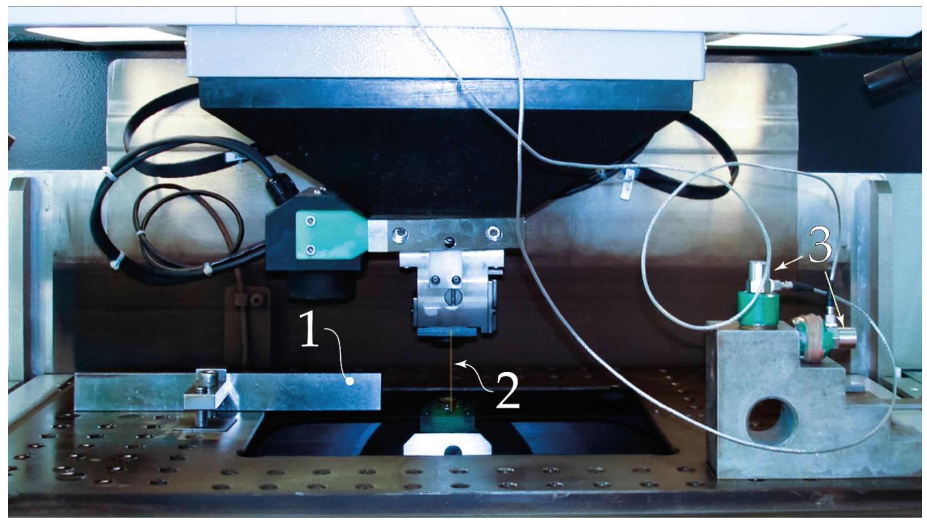
2.2. Experimental Setup

We simultaneously recorded the VA signals and discharge current during normal (stable, occurring without wire breakage) machining of workpieces made of a hard alloy composite of WC 88%, TiC 6% and Co 6%. In the experiment, AC Cut A 900 wire with a diameter of 0.2 mm was used, the properties of which are shown in Table 1.
Experimental studies were carried out using the electroerosive cut-out machine Agie Charmilles CUT 1000 OilTech (Table 2) shown in Figure 3.
Based on these records, the amplitude frequency characteristics (AFC) of the observation channel H (f) during stable machining and before breakage the wire electrode were plotted. Figure 4 shows VA signals recorded at the initial stage of processing of the composite of WC 88% plus Tic 6% plus Co 6%, when the working dielectric fluid contained a small amount of contaminants, and just before electrode breakage, when the concentration of contaminants in the dielectric fluid was at a critical level.

2.3. Monitoring of the Electrical Current Parameters

The system for monitoring the electrical current parameters in WEDM works in the following way: the CS sends a signal proportional to the measured current with a constant level equal to half the sensor supply voltage (+7.5 V) and maximum amplitude of the useful signal from the sensor of 29.7 mV (with a measured current equal to 100 A). Because the input range of the analog-to-digital converter (ADC) is ±10 V, and the bit width is 14 bits, it is necessary to match the signal from the CS with the ADC input by shifting the constant level (+7.5 V) to zero and amplifying up to +10 V. A program gain amplifier (PGA) and a compatible digital resistor (CDR) that acts as one of the resistive divider arms were used for shifting. The CDR value changes discretely from 0 to 10 kilo-ohm with a width of 8 bits via the I2C interface. PGA (1) and (2) are instrumentation amplifiers with gain controlled by means of a parallel code, and provide a gain in the range from 1 to 8000. The microcontroller (MC) calculates, based on the current signal from the ADC, the “real time” required offset and amplification coefficient and generates the controlling signal for CDR, PGA (1) and PGA (2). This automatic control allows full use of the ADC input range and the minimization of digital noise. With the use of a USB 2.0 (Universal Serial Bus) interface, the ADC-digitized signal is transmitted via MC to a computer for analysis.
Since pulse energy or the work performed by the pulse in the IEG is inconvenient for use, for generators forming voltage pulses independently of the IEG, the pulse energy is assumed to be proportional to the average current [86,87,88,89]. In the experiments, a Hall sensor was used to record the discharge current. The RMS signals from the Hall sensor after amplification and processing by a high-pass filter give information on the energy of pulses entering the IEG. The signal, which depends on the energy used for material removal, comes from an accelerometer installed on the machine table, where the workpiece is fixed. Low-frequency interference was preliminarily removed from the signal using a high-frequency filter, and then the signal’s RMS was determined, the square of which was proportional to the energy of the VA signal appearing in the elastic system due to the corresponding processes occurring in the machining zone.

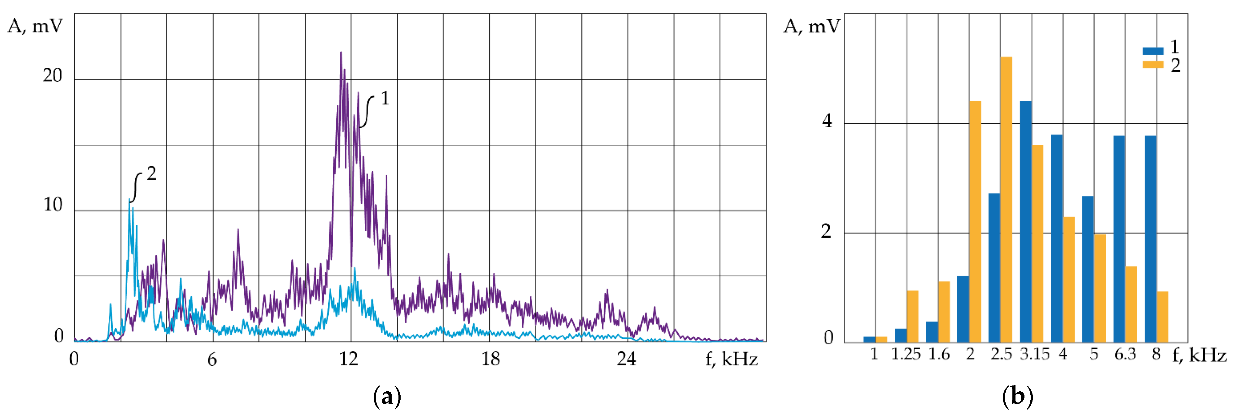
2.4. Assessment of Vibroacoustic Emissions during WEDM

Electrical pulses coming from the source of electrons and consisting of electron beams affect the workpiece surface after passing through the working dielectric fluid and forming discharge channels. The dielectric fluid properties change as contaminants accumulate or are removed. A complex sequence of pulses can be represented as a random process S1 (t) with a spectral density S1 (f), where f is the frequency. The modulus of the transfer function of the dielectric fluid is H1 (f), and it depends on the accumulation of contaminants, the distance between the electrodes and temperature. The pulses that have passed through the dielectric fluid (process S2 (t)) have a dynamic effect on the elastic system consisting of the workpiece and fixture, which has its own dynamic properties characterized by the modulus of the transfer function H2 (f). The dynamic impacts on the workpiece occur mainly due to evaporation of the workpiece material [10] and phase transitions in the workpiece material due to heating. The accelerometer installed on the workpiece side perceives vibrations (process S3 (t)) resulting from impacts of discharge pulses that have reached the workpiece surface and performed work associated with the formation of erosion craters. The amplitude spectrum S3 (f) of the signal perceived by the accelerometer is determined using the following expression:
S3 (f) = H1 (f) H2 (f) S1 (f)
The energy of this signal is the sum of the energies of signals arising from the interaction of discharges with contaminants, and secondary signals S3 (t), which appear due to the workpiece vibration. A similar scheme can be used when registering VA signals coming from the source of electrons. The sampling frequency for monitoring vibroacoustic signals was 80 kHz. The RMS amplitude values were determined for each time interval divisible by 0.01 s from 800 signal values.

3. Results and Discussion

3.1. AFCs of the Electroerosion Process of the Hard Alloy

The discharge current pulses and the AE signal recorded by an accelerometer installed on the table fixing the workpiece were used as input and output signals, respectively. Figure 4 compares the spectra of AE signals when cutting a workpiece made of hard alloy at the beginning of cutting, when the concentration of contaminants is very small (curve 1), and just before the wire electrode breakage (curve 2).
Figure 4a shows a detailed amplitude spectrum, while Figure 4b compares one-third octave spectra. As can be seen from Figure 4, in the frequency range above 6 kHz, the AE signal amplitudes dropped as the electrode breakage point was approaching. At the same time, the amplitudes in the range of 1–3 kHz increased. This was especially noticeable in the wider frequency ranges shown in Figure 4b.
In this case, when the discharge current and the high-frequency component of the AE served as the input and output signals, respectively, one could determine changes in the transmission coefficient of the dynamic system during the EDM. Figure 5a shows the changes in the RMS amplitudes of the AE signal in the range of 10–20 kHz (curve 1) and the current (curve 2) from the beginning of cutting until electrode breakage. Curve 3 in Figure 5b shows changes in signal transmission coefficient Kt, defined as the ratio of the amplitudes of the output and the input signals. Since all signals were measured in mV, the coefficient Kt is dimensionless. As seen from Figure 5b, it changed by ~20-fold during the period between the beginning of cutting and the electrode breakage.
Figure 5 shows the increase in the RMS of the discharge current provided by the CNC machine control system, accompanied by a decrease in the RMS of the amplitude of the AE signal. The decrease in the AE amplitude clearly indicates a decline in the performance of the EDM process. In response to the declining performance, the automated control system of the WEDM machine began, based on the analysis of the electrical current parameters only, to increase the discharge currents. However, the falling AE amplitude showed that at high levels of contamination of the dielectric fluid, conventional manipulations with the discharge current yielded little to no effect, as confirmed by a marked drop in the transmission coefficient independently, indicating a critical situation in the IEG zone. Another important observation based on the analysis in Figure 5 was that the directions of changes in the amplitude of the discharge current and the AE signal during the EDM process may be different.

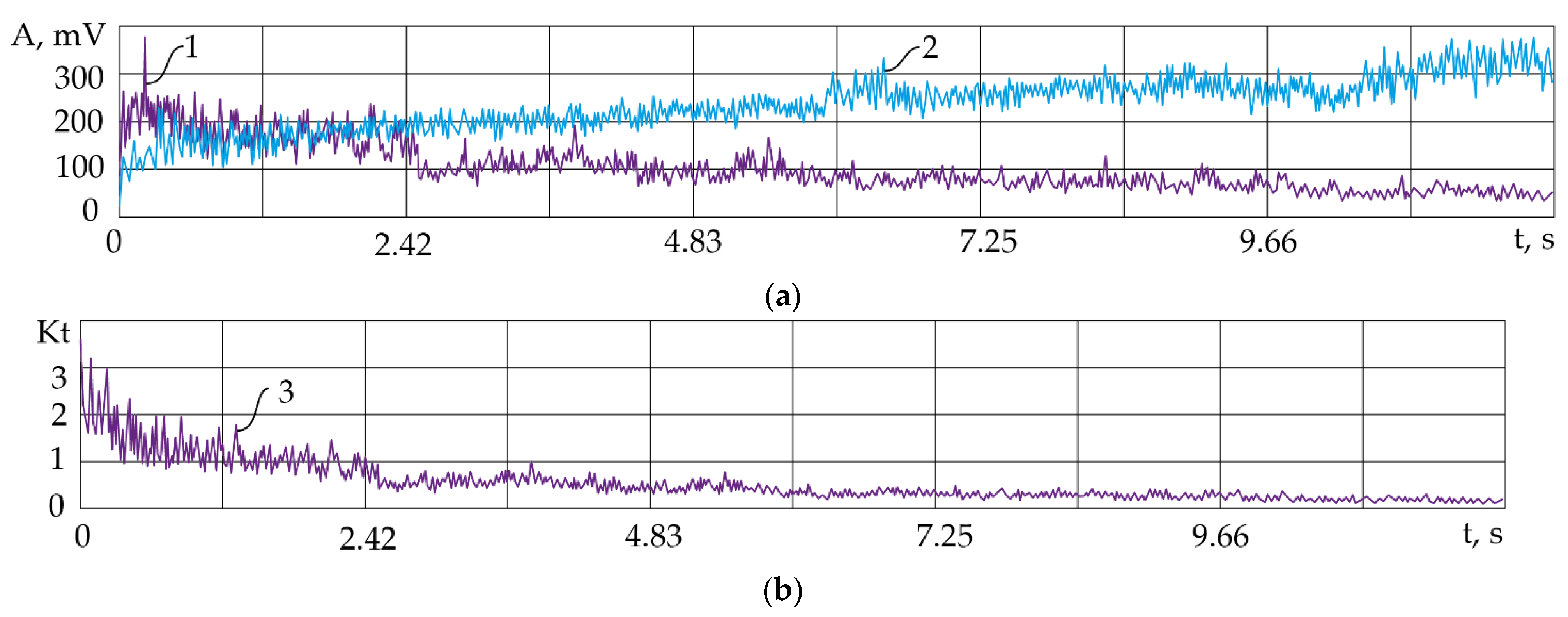
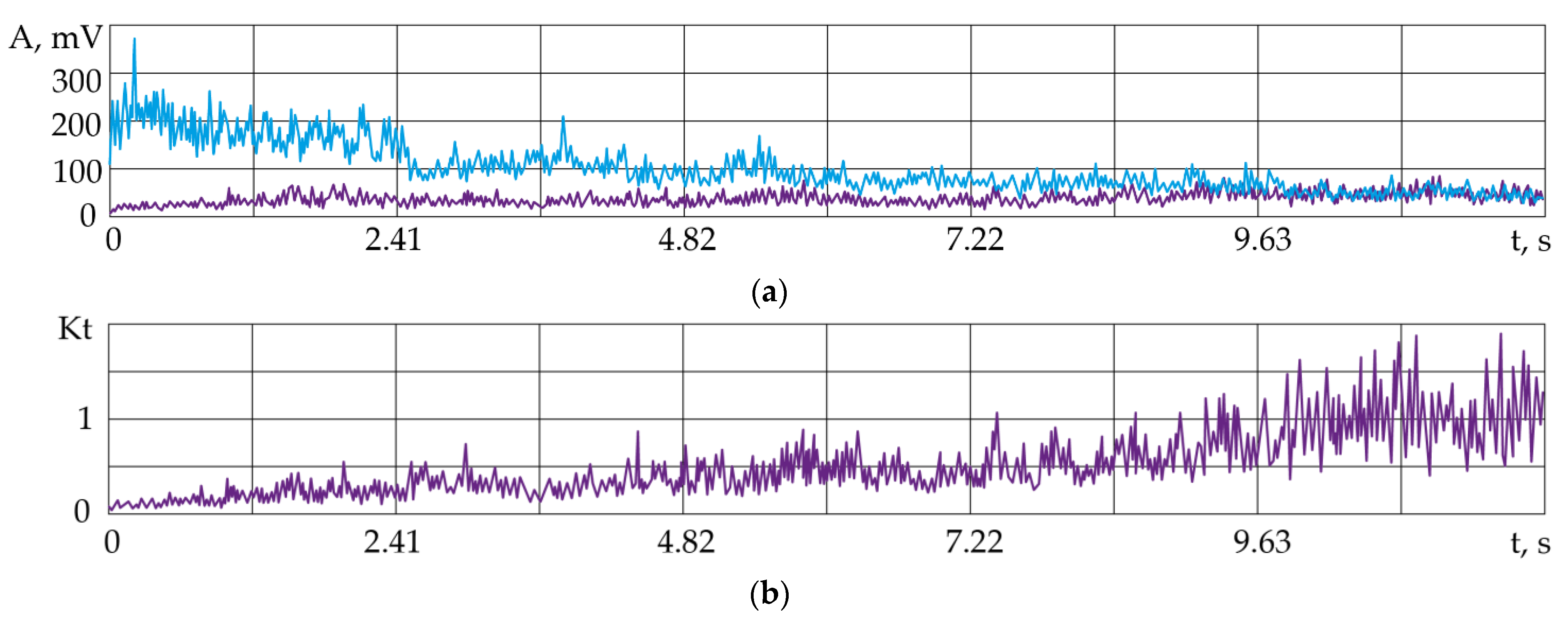
3.2. Acoustic Emission during Electrical Discharge Machining of Hard Alloys

Based on the literature review [90,91,92,93] and experimental results, it was found that the processing was occurring in the normal mode in this case, when the discharge current pulses were evenly distributed over the treated area, “choosing” the points with the highest electrical field strength. Localization of discharges occurred when the concentration of contaminants on the workpiece surface increased, and caused heating of a small area of the electrode surfaces to the melting temperature, accompanied by a marked decrease in both strength and hardness in the zone of maximum heating. Changes in the ratio of amplitudes in the AE spectrum indicate that at growing concentrations of contaminants, a growing fraction of the discharge energy was being expended on their removal, which in turn reduced the density of the discharge energy reaching the workpiece surface. At the lowered density of the discharge energy, the major fraction of the energy was expended on heating, to a relatively large depth, the electrodes, while the emission of vapors and material particles into the dielectric fluid decreased, causing a marked loss in EDM performance. In this case, phase transitions in the material being heated generated vibrations that had lower frequencies compared to those caused by evaporation, and that impacted the low-frequency range of the AE spectrum. Thus, increasing the volume of the heated material resulted in increasing the amplitudes of the AE signals in the lower frequency region shown in Figure 4. Figure 6 shows parallel recordings of AE signals in two frequency ranges, 1–3 kHz (low frequency—lf) and 10–20 kHz (high frequency—hf), and the ratio of lf to hf amplitudes in the period from the beginning of cutting to the electrode breakage.
As may be seen from Figure 6, the hf amplitude decreases, the lf amplitude slightly increases and the coefficient Kf increases by more than one order of magnitude due to the opposite trends in the hf and lf amplitudes of the AE signals. In control systems, it would be more convenient to use the dimensionless coefficient Kf, which is less sensitive to the location of the sensor and to the operational modes, as a diagnostic parameter. It is quite clear that given a known initial value of Kf, one can easily determine its permissible percentage.

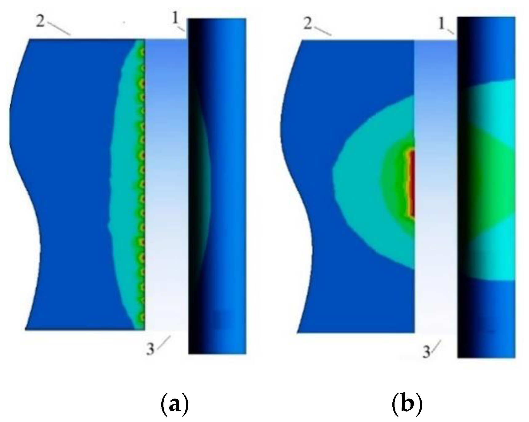
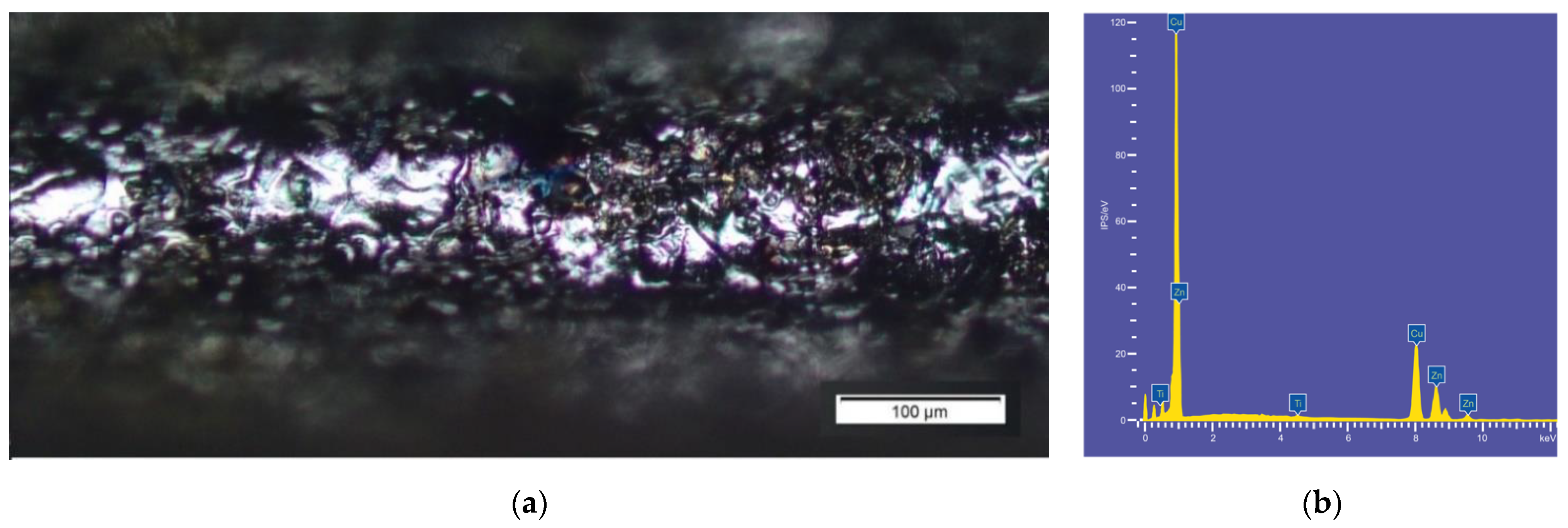
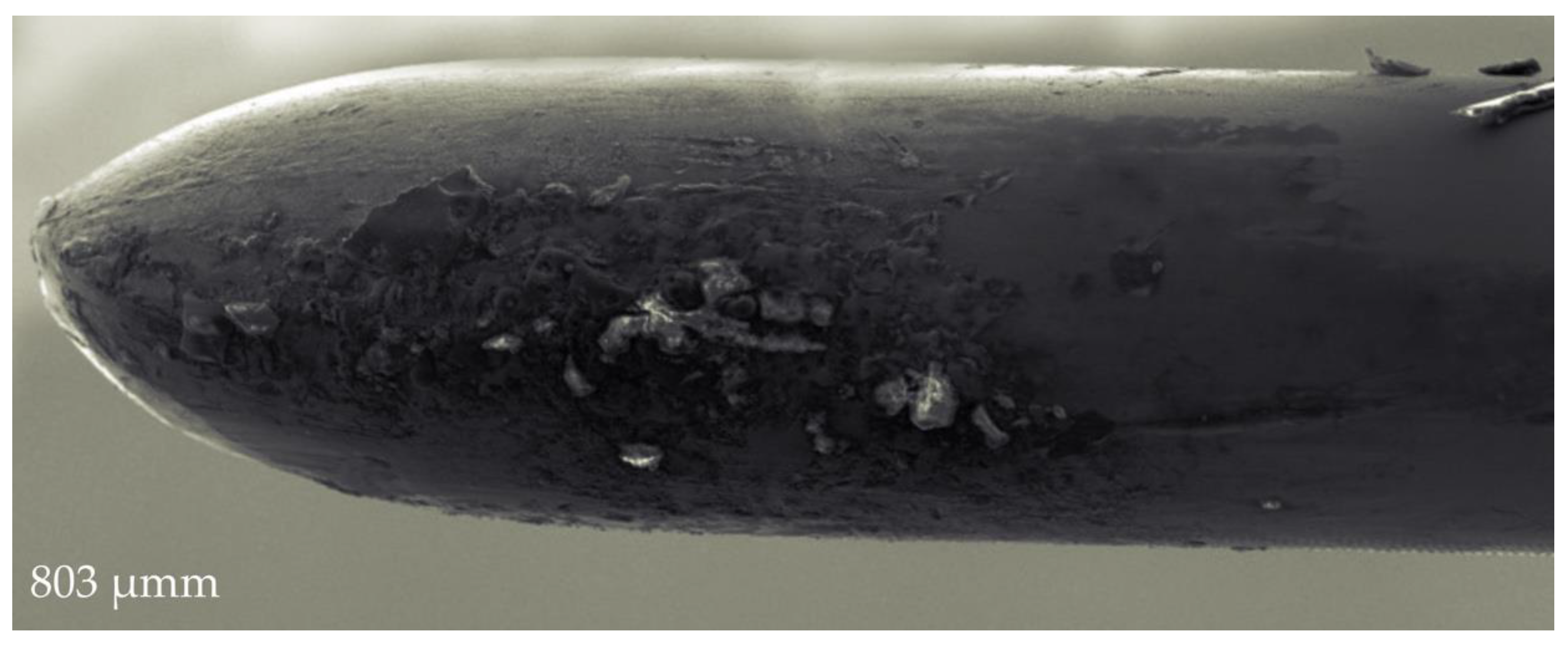
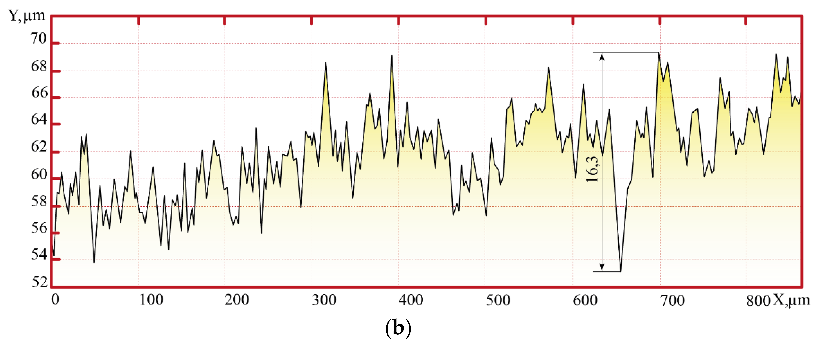
3.3. Wire Breakage and “Neck” Formation

Based on the analysis of the frequencies of acoustic emission, one can conclude that low-frequency discharge vibrations equaled and exceeded the vibrations at the initial moment, while the high-frequency vibrations behaved in the opposite manner, and the ratio of vibration amplitudes approached ~1, indicating contamination of the working area and the formation of local breakdowns of energy, dispersed over a large area, and, possibly, a reduction in the intensity of the boiling and evaporation process from the material surface. Due to the increase in temperature during the passage of the discharge through the electroerosion products, the electrode began melting.
Figure 7 shows that the electrode surface contained particles that were electroerosion products formed in the vicinity of the electrode breakage zone due to the discharge localization. An increased concentration of these inclusions in a small area in the vicinity of the wire breakage zone indicates that at the time of the wire breakage, welding of the electrodes occurred. As seen from Figure 7, the “neck” diameter was reduced several fold due to melting.
Evaluation of the surface quality at different stages of machining preceding wire breakage showed that before the breakage, the value of residual irregularities increased 2.4 fold from 16.3 μmm (Figure 8a) to 39.1 μmm (Figure 8b). A decrease in the quality of the surface being machined is caused by the contamination of the dielectric fluid with conductive particles. The formation of deep microcracks before wire breakage is caused by a local discharge passing through the electroerosion products without significant resistance, which causes an increase in the current and a decrease in the energy density in the electroerosion process.
The melting of the wire before its breakage was confirmed by the presence of adhesions on the surface being machined (Figure 9a) and the EDX analysis of the sample surface at the time of wire breakage (Figure 9b) showing the presence of the following chemical elements: 47% Cu, 27% Zn, 16% O and 1% Fe.

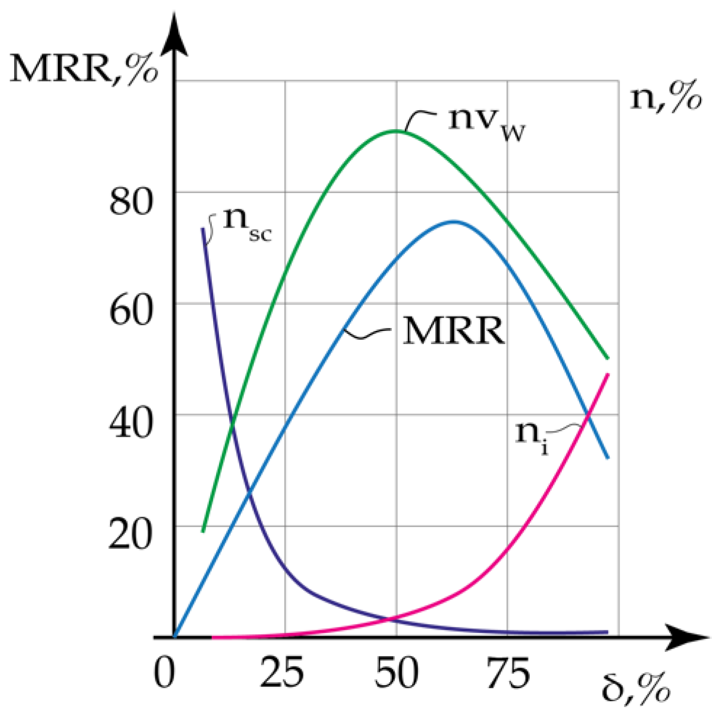
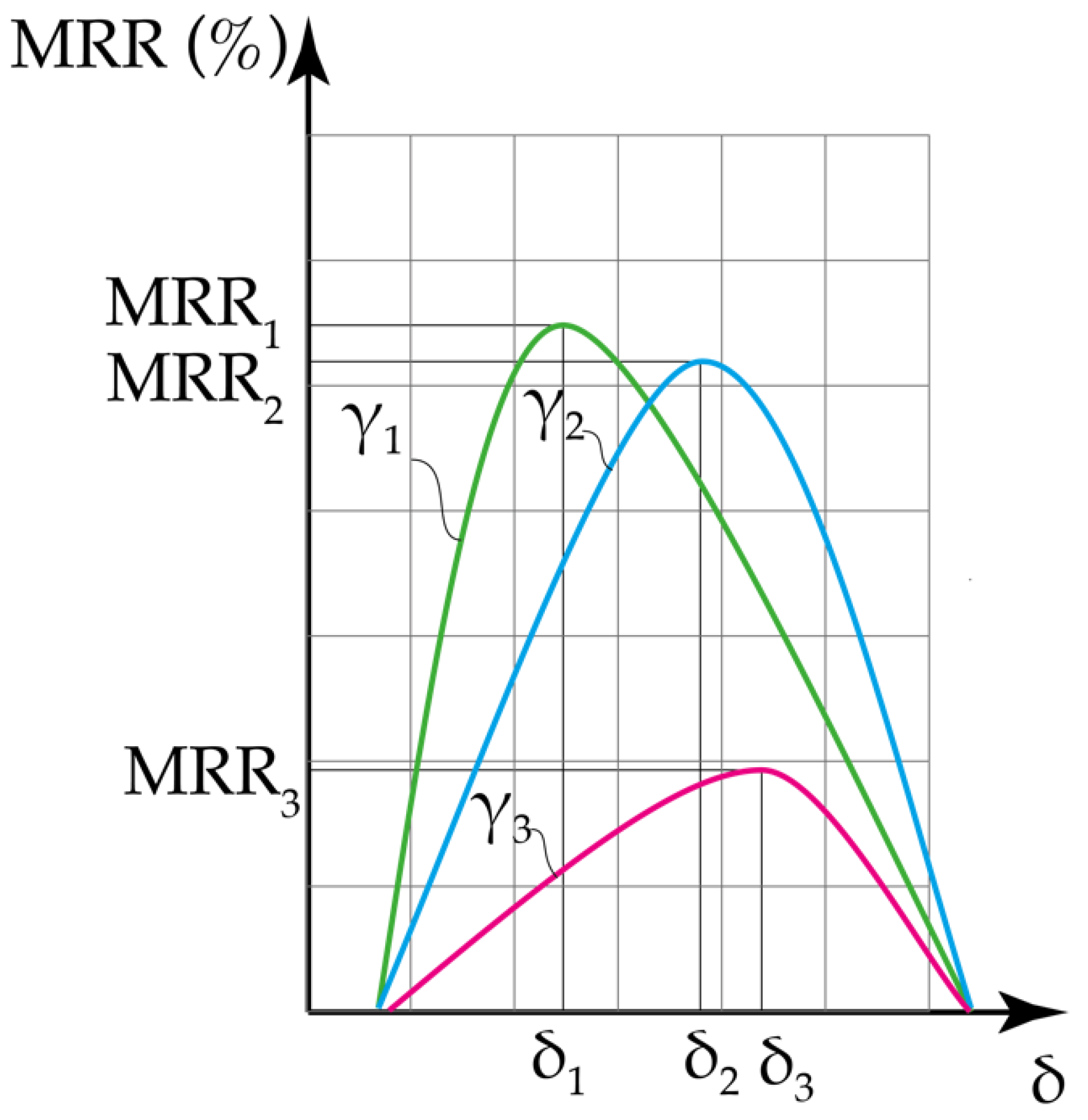
3.4. Material Removal Rate (MRR) of the WEDM

In this case, when a search for an extremum is occurring at the decreasing feed rate, the electroerosion process should be stopped to flush the IEG after reaching the minimum permissible feed rate that would automatically prevent electrode breakage. However, without a detailed experimental verification of such a control system, it would be more practical to simultaneously employ a current control system that is based on one of the parameters of the VA signal.
The presence of adhesions indicates a significant increase in temperature in the cutting zone and the formation of local discharges with a large area of contact with the workpiece caused by the contamination of the dielectric fluid. As a result, pulse energy dissipates and the formation of craters with boiling material does not occur, while the appearance of high frequencies indicates the absence of boiling and evaporation of the workpiece material. These observations fully confirm the possibility of assessing the stability and material removal rate of the electroerosion process using vibroacoustic emission signals as controlling parameters. As we mentioned earlier, the dependence of the efficiency of EDM processing on the size of the IEG has an extremum, whose position shifts towards the larger IEG with the increasing concentration of contaminants ɣ.
While it is hypothetically possible to solve the problem of continuously adjusting the IEG to the changing position of the extremum by estimating, with a large degree of uncertainty, the fraction of working pulses, one can use acoustic emission instead [94,95,96,97,98,99,100,101,102,103,104,105,106,107,108,109]. In earlier studies of the WEDM process, it was found that changes in the energy flows do not affect the position of the spectral maxima of VA signals and, thus, the amplitude-frequency pattern [110]. Although the increase in the amplitude of VA signals in different frequency ranges is not strictly proportional to the material removal rate, at the same state of the IG the amplitude increases monotonically with the growing material removal rate.
Based on this consideration, the amplitude of high-frequency vibrations (A) is related to the material removal rate (MRR) by the expression. In [10], experiments showed that simultaneous measurements of the dimensions of the craters formed via electroerosion and VA signals allow obtaining a monotonic dependence between the amplitude (A) of the high-frequency vibration signals and the MRR, determined by the volume of the craters:
A = C MRRβ, MRR = f (γ, δ)
where β = 0.45–0.55, and C is a constant dependent on the position and properties of the accelerometer. These parameters were derived empirically for a specific technological system.
As we have shown earlier for the octave bands of 1–3 and 10–20 kHz, the amplitudes of hf and lf vibrations change in the opposite directions while approaching the wire breakage point. This allows using the ratio Kf of the effective amplitudes in different (low- and high-frequency) octaves as a diagnostic parameter. Thus, by using changes in the amplitudes of the VA signal in different frequency ranges, one can approximately locate the wire breakage point and, thus, can prevent the wire breakage by timely flushing the IEG. In this case, it is necessary to determine a critical value of the amplitude ratio Kf at which the IEG should be flushed out because at the instant of a short circuit, the density of the incoming pulses’ energy drops sharply due to the increasing electrode contact area and, although at such conditions the electrode materials are still being heated, their evaporation and release of the workpiece material into the dielectric fluid stop.
There exists an extremum in the dependence of the EDM performance on the IEG value. However, its position changes as the concentration of contaminants (γ) in the dielectric fluid increases. Figure 9 shows that with increasing γ, the extremum shifts towards a large gap parameter δ, while the productivity of the EDM at the extreme point gradually decreases. In order to maintain the maximum possible EDM productivity at a growing γ, an algorithm for controlling the δ value, which is based on analysis of AE signal parameters, was proposed. A contamination of the working area with the electroerosion products drastically changes the energy transfer to the surface being machined. As may be seen from Figure 5, the increase in γ causes a lowering of both the high-frequency component of the AE signal hf and the coefficient Kf. In this case, the high-frequency component decreases from the beginning of cutting (γ~0) to the wire breakage (γ approaches the critical value) by ~4-fold (Figure 5a), while Kf decreases by 15-fold (Figure 5b) over the same period. This shows clearly that Kf= f (γ) is more sensitive to changes in γ than the high-frequency component of the AE signal.
Figure 10 shows how δ corresponding to the maximum WEDM productivity changes with increasing γ. Curves 1, 2 and 3 correspond to the initial moment of plunging (γ~0) (Kf = 15), to the middle of the cycle, when the working zone is already contaminated (Kf = 3.7), and to the critical level of contamination just before the wire breakage (Kf ~ 1), respectively. In the example shown in Figure 5, the control system based on the electrical current parameters has failed to timely detect the critical level of contamination and increased probability of a short circuit, which have led to the breakage of the wire electrode. In contrast, the analysis of the AE signal provides sufficient information for timely decreasing the electrode feed rate and flushing out the IEG. One can conclude that the extremum in the EDM productivity is continuously shifting during the entire operation cycle, depending on the degree of contamination of the dielectric fluid. This indicates that the EDM can be efficiently controlled by adjusting the electrode feed rate.
Although direct assessment of the contamination of the working dielectric fluid is currently impossible, one can, with dependence (2), find the extreme value of δ from the corresponding parameters of the AE signals. Both the amplitude of the high-frequency signal and the Kf coefficient, which is more sensitive to changes in the working zone, can be used as diagnostic parameters. However, in order to find the extremum of MRR (δ), it is unnecessary to have the exact dependence (2). To start searching for an extremum, it is necessary to establish on which branch of the MRR (δ) dependence (Figure 9) the system is located at the moment. This can be achieved by varying δ with a parallel estimate of the rise or fall in the effective amplitude of the AE signal. This will make it possible to determine the direction of change in the gap δ by increasing or decreasing the feed rate of the electrode. The change in the feed rate continues until the vicinity of the extremum is reached, where the increments in the feed rate cease to affect the change in the vibration signal amplitude. It is conceivable that the proposed algorithm can be improved by separating, at the first step, the branch of the dependence MRR (δ) by analyzing fractions of nsc and ni. In order to assess which method of searching for the extremum will give the best results, additional experiments are needed.
The first step in the algorithm of searching for the extremum in the gap parameter by monitoring the AE parameters is aimed at determining on which side of the extremum the current position of δ is located. Since (see Figure 9) the extremum shifts towards growing δ as γ increases, the first step is to increase δ by decreasing the feed rate. In that case, when this leads to a decrease in amplitudes or Kf, the direction of change in the gap δ is erroneous and the gap parameter δ should be reduced by increasing the feed rate. The decrease in δ continues until the values of the amplitudes or Kf stop growing, indicating that the position of the gap is in the vicinity of the extremum of EDM performance. In this case, when an increase in the gap parameter δ due to a decreasing feed rate leads to an increase in A or Kf, then the current gap position is on the left-hand side of the extremum, and, thus, δ should be increased further until the amplitudes or Kf stop growing. When the initial increase in the gap parameter δ does not lead to a noticeable change in the amplitude A or Kf, the feed rate is not changing, but the cycle should be continuously repeated because a tendency for the increase in the concentration of contaminants persists.
In this case, when the search for the extremum is occurring at the decreasing feed rate, the electroerosion process should be stopped to flush the IEG after reaching the minimum permissible feed rate that would automatically prevent electrode breakage. Therefore, one can conclude that the development of a reliable method for industrial WEDM of hard alloys with low thermal conductivity is achievable via the use of the feedback from the monitoring of VA signals.

4. Conclusions

In this paper, the physicomechanical nature of the WEDM of hard alloys was investigated, and the possibility of using acoustic emission parameters for controlling WEDM stability and productivity was explored. Currently, the control systems for CNC WEDM machines are based on assessment of electrical parameters such as amperage and voltage. However, existing control systems are unable to timely detect conditions at which the risk of wire breakage appears due to poor heat dissipation when hard alloys with high heat resistance and low heat conductivity are being machined, or to prevent wire breakage by stopping the electrode feed and flushing out the IEG. This is due to the presence of pulses, identified by the conventional control system as “working”, which, however, expend only a fraction of their energy on material removal, while the remaining fraction is expended on heating and removing the electroerosion products in the dielectric fluid. This indicates that a conventional control system based on the electrical parameters may not detect short circuits appearing due to the pulse localization caused by contamination of the working zone and cannot timely adjust the IEG to provide maximum WEDM productivity. In view of these circumstances, controlling the WEDM process via monitoring of the parameters of the AE signals was considered, and a concept of regulating the feed rate of the wire electrode to adjust the IEG to maximum WEDM productivity and to prevent short circuits at high levels of contamination in the working zone was developed.
In this work, we investigated the WEDM of a hard alloy consisting of 88% WC, 6% TiC and 6% Co, which has high heat resistance and electrical conductivity and low thermal conductivity. A standard (stock) automated control system supplied with the CNC WEDM machine was used for monitoring of the electrical current. The WEDM machine operation was monitored from the plunging until the breakage of the wire electrode. AE signals were recorded in octave bands with central frequencies of 1–3 and 10–20 kHz. It was found that at the initial moment when the dielectric fluid was virtually free of contaminants, the amplitude of the high-frequency component of the VA signal had its highest value. However, as the contamination level increased, the amplitude of the high-frequency component of the AE signal decreased, while the low-frequency component in an octave of 1–3 kHz increased. By the time of the wire breakage, the amplitude of the high-frequency component in the octave of 10–20 kHz had decreased more than 5-fold, the amplitude of the low-frequency component in the octave of 1–3 kHz had increased more than 2-fold, and their ratio, the coefficient Kf, decreased 12-fold. The coefficient Kf is dimensionless, less sensitive to the location of the accelerometer and more informative than the individual amplitudes in the selected frequency band; thus, it could be used as a new diagnostic parameter. The presence of a random component in changes in the concentration of contaminants in the IEG makes changes in AE parameters not strictly monotonous. However, the ranges of variation in the AE parameters allow determining the threshold/critical value at which the feed should be stopped and the IEG should be flushed out to remove the electroerosion products contaminating the working zone.
To evaluate the efficiency of Kf as a diagnostic parameter, we investigated the quality of the surface being machined at the beginning of processing and after the wire breakage. The analysis of residual irregularities on the surface at the electrode breakage point showed the presence of deep cracks and craters typical of short-circuit machining. It was also found that the workpiece surface was full of deposits/sticks, whose chemical composition was identical to that of the wire material. The presence of the deposits evidenced heating and melting of the wire due to the increased concentration of contaminants causing short circuits. It was also shown that the wire breakage was accompanied by the “neck” formation, which indicated simultaneous impacts of the local heating of the wire material and tensile forces. Due to the elevated temperature, the mechanical properties of the wire material were quickly deteriorating, a “neck” was being formed, and, finally, the wire broke. At the wire breakage point, sticks/deposits of the workpiece material and electroerosion products were clearly visible, which evidenced a partial loss of the pulses’ energy on heating the electroerosion products and electrodes. Further increase in contamination level led to short circuits and subsequent breakage of the wire electrode. The conventional control system, which is based on the assessment of voltage and amperage, was unable to detect the risk of wire breakage due to its inability to distinguish between the working pulses that fully expended their energy on material removal and those that expended only a fraction of their energy on material removal. Short circuits before wire breakage are very common, but they do not drastically increase the discharge current. This makes prompt detection of short circuits very difficult, if not impossible, thus resulting in the overheating and breakage of the wire electrode.
The analysis of VA signals, in contrast, clearly indicated the risk of wire breakage due to contamination, discharge localization and subsequent short circuits. A link between the VA signal and the contamination level is related to a loss of pulse energy on heating and removing electroerosion products. A decrease in the density of energy transferred to the workpiece surface leads to the reduced evaporation of the workpiece material and the decreased emission of vapors and particles into the dielectric working fluid, which results in the decreased amplitude of the high-frequency component of the VA signal. At the same time, the volume of the workpiece material being heated grows, causing solid–liquid phase transitions responsible for the low-frequency component of VA signal. When a short circuit occurs, the contact area of the electrodes sharply increases, and the power density of the heat flux to the workpiece surface decreases, which is responsible for an instantaneous decrease in the amplitude of the high-frequency component of the VA signal.
Due to the constant change in the concentration of contaminants in the IEG, its settings for the highest productivity of WEDM are also continuously changing. The monotonic dependence of WEDM productivity on the AE parameters suggests the possibility of adaptively adjusting the wire electrode feed rate to the highest WEDM productivity at a given (current) contamination level. The feed rate of the wire electrode should be decreased as the concentration of contaminants increases, until reaching the critical value of the diagnostic parameter, Kf, at which the feed stops and the IG flushes out.
Experimental results show that the analysis of VA signals allows for the prevention of short circuits at high levels of contamination in the working zone and, thus, elimination of the risk of wire breakage. The experimental investigation of the wire surface at the time of wire breakage confirmed both theoretical conclusions regarding the impacts of growing contamination on wire melting and breakage and the link between VA signals and the level of contamination.
The link between the AE signals and the physicomechanical nature of WEDM investigated in this work provides a clear perspective on the use of AE signals for preventing short circuits and breakage of wire electrodes and for increasing the productivity and reliability of electroerosion processes. In particular, the monitoring of AE signals can be used as a main or supplementary component in control systems for CNC WEDM machines.
Further experimental research will include validation of new WEDM performance indicators at variable current, voltage and IEG size. In order to evaluate the developed approach, variable operational modes will be used to reduce the coefficient Kf and to increase the stability of the WEDM process at high levels of contamination in the working zone. Because this new approach to monitoring and controlling the WEDM process is quite universal and flexible, it will be extended further to include a wider range of cutting tool materials with low electrical conductivity, which in turn will allow for further expansion of the WEDM application field.

Author Contributions

Conceptualization, S.N.G., M.P.K.; methodology, M.P.K., P.M.P., A.B.N.; validation, M.A.V., A.A.O., A.N.P.; formal analysis, P.M.P., M.A.V., A.A.Z.; investigation, P.M.P., A.B.N.; resources, P.M.P.; data curation, P.M.P., M.A.V., A.A.O., A.A.Z., A.N.P.; writing—original draft preparation, A.B.N., P.M.P., M.P.K.; writing—review and editing, S.N.G., A.B.N.; visualization, P.M.P., M.P.K., A.A.O., A.A.Z.; supervision, P.M.P.; project administration, S.N.G. All authors have read and agreed to the published version of the manuscript.

Funding

The study was supported by a grant from the Russian Science Foundation (project No. 21-19-00790).

Institutional Review Board Statement

Not applicable.

Informed Consent Statement

Not applicable.

Data Availability Statement

The data presented in this study are available on request from the corresponding author after obtaining the permission of an authorized person.

Acknowledgments

The authors carried out research using the equipment provided by the Center of collective use of MSTU “STANKIN” (agreement No. 075-15-2021-695, 26 July 2021).

Conflicts of Interest

The authors declare no conflict of interest.

References

  1. Chen, X.; Wang, Z.; Xu, J.; Wang, Y.; Li, J.; Liu, H. Sustainable production of micro gears combining micro reciprocated wire electrical discharge machining and precision forging. J. Clean. Prod. 2018, 188, 1–11. [Google Scholar] [CrossRef]
  2. Grigoriev, S.N.; Kozochkin, M.P.; Sabirov, F.S.; Kutin, A.A. Diagnostic systems as basis for technological improvement. Procedia CIRP 2012, 1, 599–604. [Google Scholar] [CrossRef] [Green Version]
  3. Semenishchev, E.; Voronin, V.; Zelensky, A.; Tolstova, I.; Khamidullin, I. Identification of local features on a group of images obtained in different electromagnetic ranges. In Signal Processing, Sensor/Information Fusion, and Target Recognition XXIX; SPIE: Bellingham, WA, USA, 2020. [Google Scholar]
  4. Gostimirovic, M.; Kovac, P.; Sekulic, M. An inverse optimal control problem in the electrical discharge machining. Sadhana 2018, 43, 70. [Google Scholar] [CrossRef] [Green Version]
  5. Sen, B.; Hussain, S.A.I.; Gupta, A.D.; Gupta, M.K.; Pimenov, D.Y.; Mikołajczyk, T. Application of Type-2 Fuzzy AHP-ARAS for Selecting Optimal WEDM Parameters. Metals 2021, 11, 42. [Google Scholar] [CrossRef]
  6. Grigoriev, S.; Martinov, G. The Control Platform for Decomposition and Synthesis of Specialized CNC Systems. Procedia CIRP 2016, 41, 858–863. [Google Scholar] [CrossRef] [Green Version]
  7. Straka, Ľ.; Čorný, I.; Piteľ, J. Properties Evaluation of Thin Microhardened Surface Layer of Tool Steel after Wire EDM. Metals 2016, 6, 95. [Google Scholar] [CrossRef] [Green Version]
  8. Grigoriev, S.N.; Sinopalnikov, V.A.; Tereshin, M.V.; Gurin, V.D. Control of parameters of the cutting process on the basis of diagnostics of the machine tool and workpiece. Meas. Tech. 2012, 55, 555–558. [Google Scholar] [CrossRef]
  9. Bleys, P.; Kruth, J.; Lauwers, B. Sensing and compensation of tool wear in milling EDM. J. Mater. Process. Technol. 2004, 149, 139–146. [Google Scholar] [CrossRef]
  10. Grigoriev, S.N.; Kozochkin, M.P.; Porvatov, A.N.; Zhavoronsky, P.S.; Xiaohui, J.; Pivkin, P.M. Dynamic model of electrical discharge machining and algorithm of extreme control through acoustic signal. In Proceedings of the 4th International Conference of Modeling of Nonlinear Processes and Systems, Moscow, Russia, 15–17 October 2019; Volume 224, p. 5002. [Google Scholar] [CrossRef]
  11. Grigoriev, S.; Martinov, G. Research and Development of a Cross-platform CNC Kernel for Multi-axis Machine Tool. Procedia CIRP 2014, 14, 517–522. [Google Scholar] [CrossRef] [Green Version]
  12. Sibalija, T.V.; Kumar, S.; Patel, G.M. A soft computing-based study on WEDM optimization in processing Inconel 625. Neural Comput. Appl. 2021, 33, 11985–12006. [Google Scholar] [CrossRef]
  13. Kuzin, V.V.; Grigoriev, S.N.; Volosova, M.A. The role of the thermal factor in the wear mechanism of ceramic tools: Part 1. Macrolevel. J. Frict. Wear 2014, 35, 505–510. [Google Scholar] [CrossRef]
  14. Lee, K.; Cha, S.; Kim, B.; Hong, S. Effect of WC/TiC grain size ratio on microstructure and mechanical properties of WC–TiC–Co cemented carbides. Int. J. Refract. Met. Hard Mater. 2006, 24, 109–114. [Google Scholar] [CrossRef]
  15. Sun, J.; Zhao, J.; Huang, Z.; Yan, K.; Shen, X.; Xing, J.; Gao, Y.; Jian, Y.; Yang, H.; Li, B. A Review on Binderless Tungsten Carbide: Development and Application. Nano-Micro Lett. 2020, 12, 13. [Google Scholar] [CrossRef] [Green Version]
  16. Grigoriev, S.N.; Vereschaka, A.A.; Fyodorov, S.V.; Sitnikov, N.N.; Batako, A.D. Comparative analysis of cutting properties and nature of wear of carbide cutting tools with multi-layered nano-structured and gradient coatings produced by using of various deposition methods. Int. J. Adv. Manuf. Technol. 2017, 90, 3421–3435. [Google Scholar] [CrossRef]
  17. Gong, H.; Ao, S.; Huang, K.; Wang, Y.; Yan, C. Tool path generation of ultra-precision diamond turning: A state-of-the-art review. Nanotechnol. Precis. Eng. 2019, 2, 118–124. [Google Scholar] [CrossRef]
  18. Vereschaka, A.; Tabakov, V.; Grigoriev, S.; Sitnikov, N.; Andreev, N.; Milovich, F. Investigation of wear and diffusion processes on rake faces of carbide inserts with Ti-TiN-(Ti,Al,Si)N composite nanostructured coating. Wear 2018, 416, 72–80. [Google Scholar] [CrossRef]
  19. Çiçek, A.; Kıvak, T.; Uygur, I.; Ekici, E.; Turgut, Y. Performance of cryogenically treated M35 HSS drills in drilling of austenitic stainless steels. Int. J. Adv. Manuf. Technol. 2012, 60, 65–73. [Google Scholar] [CrossRef]
  20. Chaubey, S.K.; Jain, N.K. Investigations on microgeometry of meso bevel and meso helical gears manufactured by WEDM process. Int. J. Adv. Manuf. Technol. 2017, 93, 4217–4231. [Google Scholar] [CrossRef]
  21. Di, S.; Huang, R.; Chi, G. Study on Micro-machining by Micro-WEDM. In Proceedings of the 1st IEEE International Conference on Nano/Micro Engineered and Molecular Systems, Zhuhai, China, 18–21 January 2006. [Google Scholar] [CrossRef]
  22. Kozochkin, M. Study of frictional contact during grinding and development of phenomenological model. J. Frict. Wear. 2017, 38, 333–337. [Google Scholar] [CrossRef]
  23. Oßwald, K.; Lochmahr, I.; Schulze, H.; Kröning, O. Automated Analysis of Pulse Types in High Speed Wire EDM. Procedia CIRP 2018, 68, 796–801. [Google Scholar] [CrossRef]
  24. Oshima, K.; Kunieda, M. Attempts to fabricate micro injection molding tools and assemble molded micro parts on same EDM machine. CIRP Ann. 2018, 67, 213–216. [Google Scholar] [CrossRef]
  25. Bergs, T.; Olivier, M.; Gommeringer, A.; Kern, F.; Klink, A. Surface Integrity Analysis of Ceramics Machined by Wire EDM Using Different Trim Cut Technologies. Procedia CIRP 2020, 87, 251–256. [Google Scholar] [CrossRef]
  26. Bilal, A.; Jahan, M.P.; Talamona, D.; Perveen, A. Electro-Discharge Machining of Ceramics: A Review. Micromachines 2019, 10, 10. [Google Scholar] [CrossRef] [PubMed] [Green Version]
  27. Valaki, J.B.; Rathod, P.P.; Sidpara, A.M. Sustainability Issues in Electric Discharge Machining. In Innovations in Manufacturing for Sustainability; Gupta, K., Ed.; Springer: Cham, Switzerland, 2019; pp. 53–75. [Google Scholar] [CrossRef]
  28. Kumar, A.; Kumar, V.; Kumar, J. Metallographic Analysis of Pure Titanium (Grade-2) Surface by Wire Electro Discharge Machining (WEDM). J. Mach. Manuf. Autom. 2013, 2, 1–5. [Google Scholar]
  29. Klocke, F.; Welling, D.; Klink, A.; Perez, R. Quality assessment through in-process monitoring of wire-EDM for fir tree slot production. Procedia CIRP 2014, 24, 97–102. [Google Scholar] [CrossRef] [Green Version]
  30. Uhlmann, E.; Röhner, M.; Langmack, M. Micro-EDM. In Micro and Nano Technologies, Micro-Manufacturing Engineering and Technology; Qin Yi, Ed.; Elsevier Inc.: Oxford, UK, 2010; pp. 39–58. [Google Scholar]
  31. Fonseca, J.; Marafona, J.D. The effect of deionisation time on the electrical discharge machining performance. Int. J. Adv. Manuf. Technol. 2014, 71, 471–481. [Google Scholar] [CrossRef]
  32. Okada, A.; Uno, Y.; Onoda, S.; Habib, S. Computational fluid dynamics analysis of working fluid flow and debris movement in wire EDMed kerf. CIRP Ann. 2009, 58, 209–212. [Google Scholar] [CrossRef]
  33. Mouralova, K.; Zahradnicek, R.; Benes, L.; Prokes, T.; Hrdy, R.; Fries, J. Study of Micro Structural Material Changes after WEDM Based on TEM Lamella Analysis. Metals 2020, 10, 949. [Google Scholar] [CrossRef]
  34. Grigoriev, S.N.; Nadykto, A.B.; Volosova, M.A.; Zelensky, A.A.; Pivkin, P.M. WEDM as a Replacement for Grinding in Machining Ceramic Al2O3-TiC Cutting Inserts. Metals 2021, 11, 882. [Google Scholar] [CrossRef]
  35. Ghodsiyeh, D.; Golshan, A.J.; Shirvanehdeh, A. Review on current research trends in wire electrical discharge machining (WEDM). Indian J. Sci. Technol. 2013, 6, 4128–4140. [Google Scholar] [CrossRef]
  36. Paul, T.R.; Saha, A.; Majumder, H.; Dey, V.; Dutta, P. Multi-objective optimization of some correlated process parameters in EDM of Inconel 800 using a hybrid approach. J. Braz. Soc. Mech. Sci. Eng. 2019, 41, 300. [Google Scholar] [CrossRef]
  37. Sánchez, J.; Ortega, N. Wire Electrical Discharge Machines. In Machine Tools for High Performance Machining; López de Lacalle, L., Lamikiz, A., Eds.; Springer: London, UK, 2009; Chapter 9; pp. 307–333. [Google Scholar] [CrossRef]
  38. Grigoriev, S.; Peretyagin, P.; Smirnov, A.; Solis, W.; Diaz, L.A.; Fernandez, A.; Torrecillas, R. Effect of graphene addition on the mechanical and electrical properties of Al2O3-SiCw ceramics. J. Eur. Ceram. Soc. 2017, 37, 2473–2479. [Google Scholar] [CrossRef]
  39. Kotoban, D.; Grigoriev, S.; Okunkova, A.; Sova, A. Influence of a shape of single track on deposition efficiency of 316L stainless steel powder in cold spray. Surf. Coat. Technol. 2017, 309, 951–958. [Google Scholar] [CrossRef]
  40. Uhlmann, E.; Oyanedel Fuentes, J.A.; Keunecke, M. Machining of high performance workpiece materials with CBN coated cutting tools. Thin Solid Films 2009, 518, 1451–1454. [Google Scholar] [CrossRef]
  41. Metel, A.S.; Grigoriev, S.N.; Melnik, Y.A.; Prudnikov, V.V. Glow discharge with electrostatic confinement of electrons in a chamber bombarded by fast electrons. Plasma. Phys. Rep. 2011, 37, 628–637. [Google Scholar] [CrossRef]
  42. Grigoriev, S.N.; Melnik, Y.A.; Metel, A.S.; Panin, V.V.; Prudnikov, V.V. Broad beam source of fast atoms produced as a result of charge exchange collisions of ions accelerated between two plasmas. Instrum. Exp. Tech. 2009, 52, 602–608. [Google Scholar] [CrossRef]
  43. Metel, A.S.; Grigoriev, S.N.; Melnik, Y.A.; Bolbukov, V.P. Characteristics of a fast neutral atom source with electrons injected into the source through its emissive grid from the vacuum chamber. Instrum. Exp. Tech. 2012, 55, 288–293. [Google Scholar] [CrossRef]
  44. Vereschaka, A.A.; Grigoriev, S.N.; Vereschaka, A.S.; Popov, A.Y.; Batako, A.D. Nano-scale multilayered composite coatings for cutting tools operating under heavy cutting conditions. Procedia CIRP 2014, 14, 239–244. [Google Scholar] [CrossRef] [Green Version]
  45. Grigoriev, S.N.; Pivkin, P.M.; Grechishnikov, V.A.; Petukhov, Y.E.; Volosova, M.A.; Nadykto, A.B. High-precision method for determining the optimal trajectory of movement of a conical grinding wheel relative to the helical groove of solid ceramic mills. In Emerging Imaging and Sensing Technologies for Security and Defence V; and Advanced Manufacturing Technologies for Micro-and Nanosystems in Security and Defence III; SPIE: Bellingham, WA, USA, 2020. [Google Scholar]
  46. Rivero, A.; Aramendi, G.; Herranz, S.; de Lacalle, L.L. An experimental investigation of the effect of coatings and cutting parameters on the dry drilling performance of aluminium alloys. Int. J. Adv. Manuf. Technol. 2006, 28, 1–11. [Google Scholar] [CrossRef]
  47. Metel, A.; Melnik, Y.; Mustafaev, E.; Minin, I.; Pivkin, P. Combined Processing of Micro Cutters Using a Beam of Fast Argon Atoms in Plasma. Coatings 2021, 11, 465. [Google Scholar] [CrossRef]
  48. Alexander, I.; Vladimir, G.; Petr, P.; Mihail, K.; Yuriy, I.; Andrey, V. Machining of thin-walled parts produced by additive manufacturing technologies. Procedia CIRP 2016, 41, 1023–1026. [Google Scholar] [CrossRef] [Green Version]
  49. Kozochkin, M.; Volosova, M.; Allenov, D. Effect of Wear of Tool Cutting Edge on Detail Surface Layer Deformation and Parameters of Vibro-Acoustic Signals. Mater. Sci. Forum 2016, 876, 50–58. [Google Scholar] [CrossRef]
  50. Samoylov, L.K.; Prokopenko, N.N.; Bugakova, A.V. Estimation to efficiency of the using of anti-alias filter in the A/D interface of instrumentation and control systems. In Proceedings of the IEEE East-West Design & Test Symposium (EWDTS), Kazan, Russia, 14–17 September 2018; pp. 422–425. [Google Scholar] [CrossRef]
  51. Kuntoğlu, M.; Aslan, A.; Pimenov, D.Y.; Usca, Ü.A.; Salur, E.; Gupta, M.K.; Mikolajczyk, T.; Giasin, K.; Kapłonek, W.; Sharma, S. A Review of Indirect Tool Condition Monitoring Systems and Decision-Making Methods in Turning: Critical Analysis and Trends. Sensors 2021, 21, 108. [Google Scholar] [CrossRef] [PubMed]
  52. Vereschaka, A.; Tabakov, V.; Grigoriev, S.; Sitnikov, N.; Oganyan, G.; Andreev, N.; & Milovich, F. Investigation of wear dynamics for cutting tools with multilayer composite nanostructured coatings in turning constructional steel. Wear 2019, 420, 17–37. [Google Scholar] [CrossRef]
  53. Shalaby, M.; Veldhuis, S. New Observations on High-Speed Machining of Hardened AISI 4340 Steel Using Alumina-Based Ceramic Tools. J. Manuf. Mater. Process. 2018, 2, 27. [Google Scholar] [CrossRef] [Green Version]
  54. Grigoriev, S.; Gurin, V.; Volosova, M.; Cherkasova, N. Development of residual cutting tool life prediction algorithm by processing on CNC machine tool. Mater. Werkst. 2013, 44, 790–796. [Google Scholar] [CrossRef]
  55. Grechishnikov, V.A.; Petukhov, Y.E. Prediction and Measurement of the Parameters of the Microtopography of a Surface when Turning Intricately Shaped Parts. Meas. Tech. 2015, 58, 848–853. [Google Scholar] [CrossRef]
  56. Aouici, H.; Khellaf, A.; Smaiah, S.; Elbah, M.; Fnides, B.; Yallese, M.A. Comparative assessment of coated and uncoated ceramic tools on cutting force components and tool wear in hard turning of AISI H11 steel using Taguchi plan and RMS. Sadhana 2017, 42, 2157–2170. [Google Scholar] [CrossRef] [Green Version]
  57. Grigoriev, S.N.; Volosova, M.A.; Fedorov, S.V.; Okunkova, A.A.; Pivkin, P.M.; Peretyagin, P.Y.; Ershov, A. Development of DLC-Coated Solid SiAlON/TiN Ceramic End Mills for Nickel Alloy Machining: Problems and Prospects. Coatings 2021, 11, 532. [Google Scholar] [CrossRef]
  58. Grigoriev, S.N.; Volosova, M.A.; Okunkova, A.A.; Fedorov, S.V.; Hamdy, K.; Podrabinnik, P.A.; Pivkin, P.M.; Kozochkin, M.P.; Porvatov, A.N. Electrical Discharge Machining of Oxide Nanocomposite: Nanomodification of Surface and Subsurface Layers. J. Manuf. Mater. Process. 2020, 4, 96. [Google Scholar] [CrossRef]
  59. Slătineanu, L.; Dodun, O.; Coteaţă, M.; Nagîţ, G.; Băncescu, I.B.; Hriţuc, A. Wire Electrical Discharge Machining—A Review. Machines 2020, 8, 69. [Google Scholar] [CrossRef]
  60. Yan, M.T. An adaptive control system with self-organizing fuzzy sliding mode control strategy for micro wire-EDM machines. Int. J. Adv. Manuf. Technol. 2010, 50, 315–328. [Google Scholar] [CrossRef]
  61. Shandilya, P.; Jain, P.K.; Jain, N.K. On wire breakage and microstructure in WEDC of SiCp/6061 aluminum metal matrix composites. Int. J. Adv. Manuf. Technol. 2012, 61, 1199–1207. [Google Scholar] [CrossRef]
  62. Bian, J.; Ma, B.; Ai, H.; Qi, L. Experimental Study on the Influence of Tool Electrode Material on Electrochemical Micromachining of 304 Stainless Steel. Materials 2021, 14, 2311. [Google Scholar] [CrossRef] [PubMed]
  63. Tan, P.C.; Yeo, S.H. Modelling of overlapping craters in micro-electrical discharge machining. J. Phys. D Appl. Phys. 2008, 41, 205302. [Google Scholar] [CrossRef]
  64. Asgar, E.; Singholi, A.K.S. Parameter study and optimization of WEDM process: A Review. IOP Conf. Ser. Mater. Sci. Eng. 2018, 404, 012007. [Google Scholar] [CrossRef]
  65. Kumar, R.; Choudhury, S.K. Prevention of wire breakage in wire EDM. Int. J. Mach. Mach. Mater. 2011, 9, 86–102. [Google Scholar] [CrossRef]
  66. Rajurkar, K.P.; Wang, W.M. Thermal modeling and on-line monitoring of wire-EDM. J. Mater. Process. Technol. 1993, 38, 417–430. [Google Scholar] [CrossRef]
  67. Han, B.; Zhu, S.; Dong, W.; Bai, Y.; Ding, H.; Luo, Y.; Di, P. Electrochemical corrosion behavior of hot-pressing sintered WC-Al2O3 composite in alkaline and acidic solutions. J. Mater. Sci. 2021, 56, 4120–4134. [Google Scholar] [CrossRef]
  68. Kashif, I.; Muhammad, U.F.; Saqib, A.; Muhammad, A.A.; Shafiq, A.; Ahmed, M. El-Sh. A comprehensive investigation of geometrical accuracy errors during WEDM of Al6061-7.5%SiC composite. Mater. Manuf. Process. 2021, 36, 362–372. [Google Scholar] [CrossRef]
  69. Zhang, Z.; Ming, W.; Zhang, G.; Huang, Y.; Wen, X.; Huang, H. A new method for on-line monitoring discharge pulse in WEDM-MS process. Int. J. Adv. Manuf. Technol. 2015, 81, 1403–1418. [Google Scholar] [CrossRef]
  70. Wu, H.; Wang, T.; Wang, J. Research on discharge state detection of finishing in high-speed wire electrical discharge machine. Int. J. Adv. Manuf. Technol. 2019, 103, 2301–2317. [Google Scholar] [CrossRef]
  71. Zhang, X.; Liu, Y.; Wu, X.; Niu, Z. Intelligent pulse analysis of high-speed electrical discharge machining using different RNNs. J. Intell. Manuf. 2020, 31, 937–951. [Google Scholar] [CrossRef]
  72. Li, Z.-L.; Chu, H.-Y.; Xi, X.-C.; Xia, W.-W.; Sun, Y.-X.; Zhao, W.-S. Improving reciprocating traveling WEDM performance by a new adaptive servo feedrate control system. Int. J. Adv. Manuf. Technol. 2021, 114, 1409–1425. [Google Scholar] [CrossRef]
  73. Banu, A.; Ali, M.Y.; Rahman, M.A. Investigation of process parameters for stable micro dry wire electrical discharge machining. Int. J. Adv. Manuf. Technol. 2019, 103, 723–741. [Google Scholar] [CrossRef]
  74. Niamat, M.; Sarfraz, S.; Aziz, H.; Jahanzaib, M.; Shehab, E. Effect of Different Dielectrics on Material Removal Rate, Electrode Wear Rate and Microstructures in EDM. Procedia CIRP 2017, 60, 2–7. [Google Scholar] [CrossRef]
  75. Jahan, M.; Wong, Y.S.; Rahman, M. A study on the fine-finish die-sinking micro-EDM of tungsten carbide using different electrode materials. J. Mater. Process. Technol. 2009, 209, 3956–3967. [Google Scholar] [CrossRef]
  76. Rajurkar, K.P.; Wei, B.; Kozak, J.; Mcgeough, J.A. Modelling and Monitoring Interelectrode Gap in Pulse Electrochemical Machining. CIRP Ann. Manuf. Technol. 1995, 44, 177–180. [Google Scholar] [CrossRef]
  77. Chai, M.; Li, Z.; Yan, H.; Huang, Z. Flow field characteristics analysis of interelectrode gap in electrochemical machining of film cooling holes. Int. J. Adv. Manuf. Technol. 2021, 112, 525–536. [Google Scholar] [CrossRef]
  78. Selvakumar, G.; Jiju, K.B.; Veerajothi, R. Experimental study on wire electrical discharge machining of tapered parts. Arab. J. Sci. Eng. 2016, 41, 4431–4439. [Google Scholar] [CrossRef]
  79. Oniszczuk, D.; Swiercz, R. An investigation into the impact of electrical pulse character on surface texture in the EDM and WEDM process. Adv. Manuf. Sci. Technol. 2012, 36, 43–53. [Google Scholar]
  80. Dinesh, S.; Pillai, T.; Parthiban, F.; Kadasari, R. Modelling of WEDM process for machining ASTM 52100 steel. Mater. Today Proc. 2020, 37, 1103–1106. [Google Scholar] [CrossRef]
  81. Balan, A.S.S.; Giridharan, A. A progress review in wire electrical discharge machining process. Int. J. Autom. Mech. Eng. 2017, 14, 4097–4124. [Google Scholar] [CrossRef]
  82. Diver, C.; Atkinson, J.; Helml, H.J.; Li, L. Micro-EDM drilling of tapered holes for industrial applications. J. Mater. Process. Technol. 2004, 149, 296–303. [Google Scholar] [CrossRef]
  83. Chen, Z.; Huang, Y.; Huang, H.; Zhang, Z.; Zhang, G. Three-dimensional characteristics analysis of the wire-tool vibration considering spatial temperature field and electromagnetic field in WEDM. Int. J. Mach. Tools Manuf. 2015, 92, 85–96. [Google Scholar] [CrossRef]
  84. Sun, Y.; Gong, Y.D.; Wen, X.L.; Yin, G.Q.; Meng, F.T. Micro milling characteristics of LS-WEDM fabricated helical and corrugated micro end mill. Int. J. Mech. Sci. 2019, 167, 105277. [Google Scholar] [CrossRef]
  85. Koenraad, B.; Vleugels, P.; Salehi, A.; Van der Biest, O.; Lauwers, B.; Liu, W. EDM machinability and frictional behaviour of ZrO2-TiCN composites. Int. J. Mach. Mach. Mater. 2008, 3, 226–240. [Google Scholar] [CrossRef]
  86. Zhou, Z.; Fang, X.; Zeng, Y.; Zhu, D. Generating micro grooves with a semicircular cross-section using wire electrochemical micromachining. Int. J. Adv. Manuf. Technol. 2020, 110, 2929–2940. [Google Scholar] [CrossRef]
  87. Antar, M.T.; Soo, S.L.; Aspinwall, D.K.; Jones, D.; Perez, R. Productivity and workpiece surface integrity when WEDM aerospace alloys using coated wires. Procedia Eng. 2012, 19, 3–8. [Google Scholar] [CrossRef] [Green Version]
  88. Schulze, H.; Juhr, H. Influence of needle pulse shifting on the basis pulse for wire-EDM of hard metals. In Proceedings of the 16th International Symposium on Electromachining (ISEM XVI), Shanghai, China, 19–23 April 2010; pp. 249–253. [Google Scholar]
  89. Alduroobi, A.A.A.; Ubaid, A.M.; Tawfiq, M.A.; Elias, R.R. Wire EDM process optimization for machining AISI 1045 steel by use of Taguchi method, artificial neural network and analysis of variances. Int. J. Syst. Assur. Eng. Manag. 2020, 11, 1314–1338. [Google Scholar] [CrossRef]
  90. Nemilov, E.F. Spravochnik po Elektroerozionnoi Obrabo tke Materialov. In Handbook on Electrodischarge Treatment of Materials; Mashinostroenie: Leningrad, Russia, 1989. [Google Scholar]
  91. Artamonov, B.A.; Volkov, Y.S. Analiz Modelei ele Ktrokhimicheskoi i Elektroerozionnoi Obrabotki. Chast’ 2. Modeli Protsessov Elektroerozionnoi Obrabotki. Provolochnaya Vyrezka. In Analysis of Models of Electrochemical and Electrodischarge Treatment, Part 2: Models of Electrodischarge Treatment. Wire Cutting; Vseross. Nauchno Issled. Inst. Patent. Inform.: Moscow, Russia, 1991. [Google Scholar]
  92. Korenblyum, M.V.; Levit, M.L.; Livshits, A.L. Adaptivnoe upravlenie elektroerozionnymi stankami. In Adaptive Control of EDM Machines; Nauch. Issled. Inst. Mashinostr.: Moscow, Russia, 1977. [Google Scholar]
  93. Lipchanskij, A.B.; Nechaev, G.G. Experimental study of the processes produced by electroerosion machining with applying ultrasonic vibrations to nonprofiling wire electrode. EDM 1991, 157, 5–9. [Google Scholar]
  94. Oh, S.-J.; Kim, B.-S.; Yoon, J.-K.; Hong, K.-T.; Shon, I.-J. Enhanced mechanical properties and consolidation of the ultra-fine WC–Al2O3 composites using pulsed current activated heating. Ceram. Int. 2016, 42, 9304–9310. [Google Scholar] [CrossRef]
  95. Kozak, J.; Rajurkar, K.P.; Makkar, Y. Selected problems of micro-electrochemical machining. J. Mater. Proc. Technol. 2004, 149, 426–431. [Google Scholar] [CrossRef]
  96. Melnik, Y.A.; Kozochkin, M.P.; Porvatov, A.N.; Okunkova, A.A. On Adaptive Control for Electrical Discharge Machining Using Vibroacoustic Emission. Technologies 2018, 6, 96. [Google Scholar] [CrossRef] [Green Version]
  97. Dwaraka, R.; Arunachalam, N. Investigation on the effect of EDM process variables and environments on acoustic emission signals. Mach. Sci. Technol. 2020, 24, 638–662. [Google Scholar] [CrossRef]
  98. Dwaraka, R.; Arunachalam, N. Investigation on non-invasive process monitoring of Die Sinking EDM using Acoustic Emission signals. Procedia Manuf. 2018, 26, 1471–1482. [Google Scholar] [CrossRef]
  99. Cabrera, M.; Dahmani, R.; Layouni, Y.; Semet, V. Micro EDM Milling with Electrochemical Fabrication of Ultra-thin Microtools and Mapping of Electrical Microdischarges. Procedia CIRP 2016, 42, 650–655. [Google Scholar] [CrossRef]
  100. Kun, X.; Yongbin, Z.; Li, P.; Di, Z. Vibration assisted wire electrochemical micro machining of array micro tools. Precis. Eng. 2016, 47, 487–497. [Google Scholar] [CrossRef]
  101. Grigoriev, S.; Martinov, G. Scalable Open Cross-Platform Kernel of PCNC System for Multi-Axis Machine Tool. Procedia CIRP 2012, 1, 238. [Google Scholar] [CrossRef]
  102. El-Hofy, H. Vibration-assisted electrochemical machining: A review. Int. J. Adv. Manuf. Technol. 2019, 105, 579–593. [Google Scholar] [CrossRef]
  103. Khan, S.A.; Rehman, M.; Farooq, M.U.; Ali, M.A.; Naveed, R.; Pruncu, C.I.; Ahmad, W. A Detailed Machinability Assessment of DC53 Steel for Die and Mold Industry through Wire Electric Discharge Machining. Metals 2021, 11, 816. [Google Scholar] [CrossRef]
  104. Kumar, S.S.; Uthayakumar, M.; Kumaran, S.T.; Parameswaran, P.; Haneef, T.K.; Mukhopadhyay, C.K.; Rao, B.P.C. Performance monitoring of WEDM using online acoustic emission technique. Silicon 2018, 10, 2635–2642. [Google Scholar] [CrossRef]
  105. Kovac, P.; Rodic, D.; Pucovsky, V.; Savkovic, B.; Gostimirovic, M. Application of fuzzy logic and regression analysis for modeling surface roughness in face milliing. J. Intell. Manuf. 2013, 24, 755–762. [Google Scholar] [CrossRef]
  106. Li, C.; Bai, J.; Guo, Y.; Lu, Z. Monitoring technology of gap discharge status based on floating threshold for WEDM. In Proceedings of the 16th International Symposium on Electromachining, Non-traditional Machining Society of CMES, Shanghai, China, 19–23 April 2010; pp. 271–274. [Google Scholar]
  107. Dabade, U.A.; Karidkar, S.S. Analysis of response variables in WEDM of Inconel 718 using Taguchi technique. Procedia CIRP 2016, 41, 886–891. [Google Scholar] [CrossRef] [Green Version]
  108. Boopathi, S.; Sivakumar, K. Experimental comparative study of near-dry wire-cut electrical discharge machining (WEDM). Eur. J. Sci. Res. 2012, 75, 472–481. [Google Scholar]
  109. Tzeng, Y.; Chen, F. Multiobjective optimization of highspeed EDM process using a Tagachi fuzzybased approach. Mater. Des. 2007, 28, 1159–1168. [Google Scholar] [CrossRef]
  110. Gutkin, B.G. Automated EDM; Mechanical Engineering: Leningrad, Russia, 1971. [Google Scholar]
Figure 1. Temperature fields during WEDM in the cases of (a) uniform distribution of discharges over the treated surface; and (b) localization of discharges in a relatively small area. Symbols 1, 2 and 3 denote zones of the electrode-tool, electrode-workpiece and interelectrode gap with the dielectric fluid, respectively.
Metals 11 01865 g001
Figure 2. Dependence of the material removal rate (MRR) of the EDM process and the number (percentage of the maximum) of working pulses nw, idle pulses ni and short-circuit pulses nsc on the IEG parameter δ.
Metals 11 01865 g002
Figure 3. Working area of the Agie Charmilles CUT 1000 OilTech machine with installed accelerometers: 1—electrode- workpiece; 2—electrode- tool; 3—accelerometer and acoustic emission sensors.
Metals 11 01865 g003
Figure 4. Comparison of the spectra of AE signals during the processing of hard alloy: the beginning of cutting (1) and just before the breakage of the wire electrode (2): (a) detailed amplitude spectra; (b) 1/3 octave bands with numbers showing the central frequencies of 1/3 octave bands.
Metals 11 01865 g004
Figure 5. Changes in the RMS amplitudes of the AE signals in the range of 10–20 kHz (curve 1, (a)), current (curve 2 (a)) and the transfer coefficient Kt (curve 3 (b)) during the period between beginning of operation and the electrode breakage.
Metals 11 01865 g005
Figure 6. RMS amplitudes of the AE signals during the solid carbide segment in the frequency ranges. Curve 1: 1–3 kHz, curve 2: 10–20 kHz (a); curve 3: the change in the ratio of lf to hf amplitudes (coefficient Kf) (b).
Metals 11 01865 g006
Figure 7. Wire breakage and the “neck” diameter reduced several fold due to melting.
Metals 11 01865 g007
Figure 8. Microtexture of the surface being processed. At the initial moment of operation (low concentration of contaminants) (a), and just before the wire breakage (critical level of contamination) (b).
Metals 11 01865 g008aMetals 11 01865 g008b
Figure 9. The surface being machined at the moment of wire breakage: (a) a photo of the surface at the moment of wire breakage; (b) elemental quantitative EDX analysis of the wire melting and breakage zone.
Metals 11 01865 g009
Figure 10. The dependence of EDM productivity ( MRR = f ( γ , δ ) ) on the IEG and on the concentration of contaminants (γ1 < γ2 < γ3).
Metals 11 01865 g010
Table 1. Properties of the wire electrode used in the WEDM process.
CoatingConductivity
(% IACS)
Elongation (%)MaterialTensile Strength (N/mm2)
Zn221.5Brass CuZn37900
Table 2. Technical specification of the electroerosive cut-out machine Agie Charmilles CUT 1000 OilTech.
ParameterValue
Angle/workpiece height, °/mm±3°/80
Workpiece dimensions (W × D × H), mm300 × 200 × 80
Maximum workpiece weight, kg.35
Wire diameters, mm0.02–0.2
Roughness, Ra μmm0.03
Publisher’s Note: MDPI stays neutral with regard to jurisdictional claims in published maps and institutional affiliations.

