1. Introduction
In the automotive industry, welding Al alloys to steel has important implications for reducing the weight of the vehicle [
1]. More recently, numerous efforts to join Al alloys to steel focused on the improvement of the welding method and welding process [
2,
3,
4,
5,
6]. To decrease the heat input during welding, laser welding, hybrid laser and arc welding, diffusion welding and explosive welding were used to join Al alloys to steel. To improve the bonding properties of the Al/steel joint, Chen et al. [
7] conducted laser welding of Al and steel by adding a Ni interlayer, and detected the occurrence of a lot of intermetallic compounds of FeAl
3 at the Al/steel interface. However, the enhancements in bonding properties of the Al/steel joint were relatively limited, because the brittle and hard Al–Fe intermetallic compounds were difficult to avoid during the higher heat input conditions of fusion welding, which could be a source of cracking.
Friction stir welding (FSW), as a new solid state joining technology, was invented by the welding institute (TWI) of the United Kingdom in 1991, and has been widely applied to Al alloys [
8]. In recent years, with the development of FSW technology, Al alloys and steel were joined using FSW to obtain sound welds [
9,
10,
11,
12,
13,
14,
15,
16,
17,
18,
19,
20]. This is because of the low heat input during FSW, where lower peak temperature and shorter heating time are implemented compared to other conventional welding techniques. Thus, the degree of diffusion between Al and Fe is limited, producing a relatively thin reaction layer at the Al/steel interface. Kimapong et al. [
9] carried out friction stir lap welding (FSLW) of 5083 Al alloy to low-carbon steel, and studied the effects of welding parameters on the mechanical properties of the weld. It was suggested that as the heat input increased, the FeAl
3 compound at the interface became thicker, causing an obvious reduction in bonding properties. Furthermore, Chen et al. [
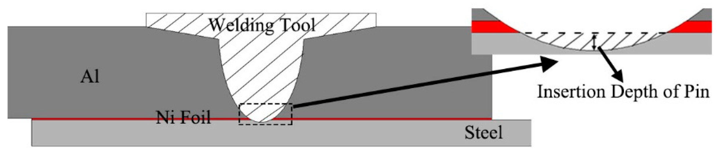
10] proposed that in the FSLW of Al alloy 6060 to mild steel, the stirring pin position relative to the steel surface had a significant influence on the bonding properties of the weld. When the stirring pin only just came into contact with the steel surface, the bonding strength of the Al/steel interface was at its maximum. Additionally, recent studies [
11,
12,
13,
14,
15] indicated that besides FSW parameters such as welding speed, rotation rate and tool position, the bonding of the steel/Al interface is also closely related to the Al/steel interfacial interlayer or steel surface coating. It was pointed out that the galvanized coating or Zn interlayer can improve the steel/Al interfacial bonding to a certain extent because the oxidation film on the Al substrate’s surface is removed by the molten Zn liquid [
11,
12,
13,
14]. Similarly, Haghshenas et al. [
15] studied the FSLW of Al alloy 5754 to 22 MnB5 steel with an Al-12Si coating. However, brittle and hard Fe–Al compounds continued to exist in the vicinity of the interfaces, which were difficult to avoid. Therefore, the enhancement in the bonding is relatively limited, and fractures still tend to occur near the interface.
Based on the above studies, it can be concluded that coatings or interlayers with lower melting points find it difficult to suppress the diffusion between Fe and Al. Thus, introducing an interlayer material that can effectively suppress diffusion between Fe and Al and provide the desired mechanical properties is important, in order to obtain an excellent Al/steel joint. Therefore, in this study, a pure Ni interlayer with a high melting point and sound mechanical properties was used in the FSLW of high-strength interstitial-free (IF) steel and an Al alloy. The influences of the Ni interlayer on the microstructure and mechanical properties of the FSLW Al/steel joint were studied.
3. Results and Discussion
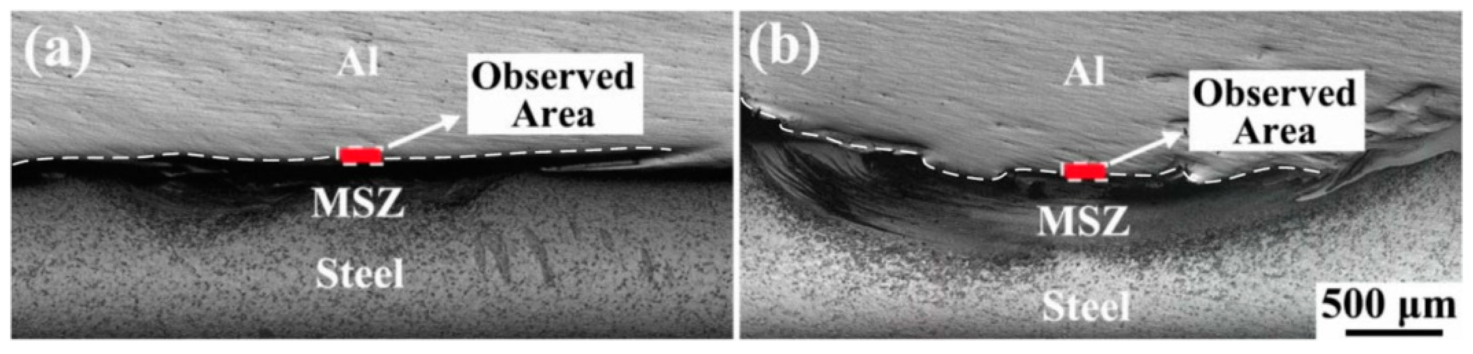
Figure 3 shows macrographs of the FSLW joints without/with a Ni interlayer at an insertion depth of 0.1 mm, and defect-free joints were achieved under both welding conditions. The area observed in
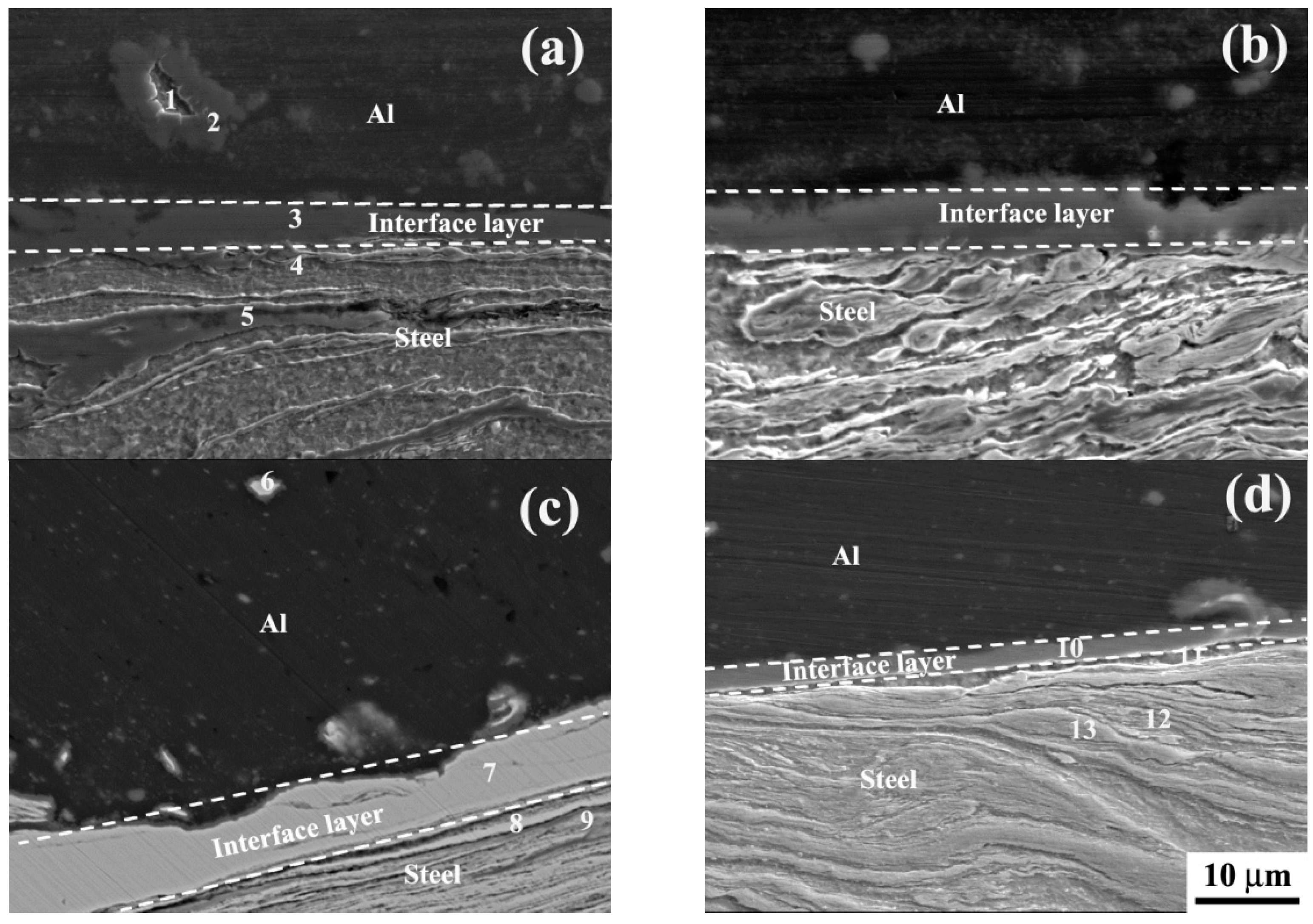
Figure 3 was selected for our analysis. The area contains three parts: Al substrate, Ni interlayer and mixed stirring zone (MSZ). The highly magnified micrographs at the Al/steel interface without/with a Ni interlayer are shown in
Figure 4. For different welding processes, a continuous interface layer was observed without any defects, such as voids and cracks.
Table 2 shows that the thicknesses of the interface layer for processes I, II, III and IV were ~3.3, 7.2, 6.1 and 1.8 μm, respectively, exhibiting an obvious differences in thickness. In this case, with increased insertion depth of the stirring pin, the Al/steel interface thickness increased significantly, but decreased after adding the Ni interlayer. Typically, the Al/steel interface layer was produced via diffusion between Al and steel [
9]. Increased insertion depth can increase the friction heat and the volume of steel stirred from the steel substrate, producing a relatively thicker interface layer because of the substantial contact and significant diffusion between Al and Fe. However, for the weld containing Ni, the thinned interface layer had to be associated with the Ni interlayer, which exerted a significant effect on the element diffusion at the interface.
Table 3 shows the elemental point analysis results in the Al/steel joints using EPMA. It was identified that the interface layers for processes I, II and IV mainly consisted of Al and Fe with different Al/Fe atom ratios, and the interface layer for process III mainly consisted of Ni and Fe. This further suggests that the Ni interlayer played a critical role in the diffusion between Al and steel. Moreover,
Figure 4 also shows that in the Al alloy substrates, there were some small fragments. From
Figure 4a and the EPMA results in
Table 3, it was observed that the fragments within the weld without Ni mainly contained Fe and Al. This implied that these fragments came from the steel substrate. This was expected, since the helix stirring action of screw threads on the stirring pin caused the steel substrate to be broken-up and thrown into the Al substrate. Moreover,
Table 3 reveals that the fragment exhibited inhomogeneous distribution of Fe; i.e., in the center of the fragment, the content of Fe element was high compared to the outer surface of the fragment. The fragments for welds with Ni interlayer primarily contained Ni. Clearly, this was due to the Ni interlayer substituting the steel substrate stirred by the pin.
During the FSW process, the stirring pin with threads causes laminar plastic deformation of the material, resulting in the formation of MSZ with a laminar structure. Similarly, Karrar et al. [
21] also observed laminar structure in the SZ of FSW Al–copper alloy. The MSZ was observed underneath the interface layer, and the location of MSZ as shown in
Figure 3. From
Table 3, it was determined that the alternate lamellae in the MSZ without a Ni interlayer consisted of Fe and Al, but the Al/Fe ratio was different. In this case, the screw threads on the stirring pin significantly mixed Fe and Al within the MSZ in the form of alternate lamellae of Fe and Al layers. Simultaneously, these Al layers were almost completely consumed to form an Al–Fe intermetallic compound, and only a small amount of the Al layer diffused into the Fe layer to form an α-Fe solid solution layer because of the higher solid solubility of Al in Fe [
7]. Thus, the MSZ consisted of α-Fe solid solution with a lower Al/Fe ratio and an Fe–Al intermetallic compound with a higher Al/Fe ratio. Similarly, Chen et al. [
11] also found that the MSZ at the weld without Ni was made up of ferrite grains and Al-Fe compounds, but the compound composition was not analyzed. By comparison, these lamellae within the MSZ containing the Ni interlayer were primarily composed of Ni and Fe elements with various Ni/Fe ratios, as shown in
Table 3. Clearly, in the MSZ, Al was not present, meaning that the Ni interlayer had a critical effect on the formation of the MSZ.
Previously, it has been stated that among the series of Fe–Al intermetallic compounds, the Gibbs free energy of Fe
2Al
5 intermetallic compound is the lowest [
15]. Thus, the diffusion between Fe and Al leads to the formation of an Fe
2Al
5 compound layer. Given that the diffusion coefficient of Fe into Al is ~30 times that of Al into Fe, the reaction kinetics of Fe–Al compounds is governed by the diffusion of Fe element [
20]. Meanwhile, the stable Fe
2Al
5 compound layer had an orthorhombic crystal system with lower atomic arrangement density of 0.69. Thus, Fe can diffuse readily across the thin Fe
2Al
5 compound layer that is formed first, producing a relatively thick Fe–Al compound layer. However, if the diffusion of Fe into Al can be inhibited, the reactivity of Fe–Al compounds will be significantly reduced, thereby suppressing the formation of Fe–Al intermetallic compounds.
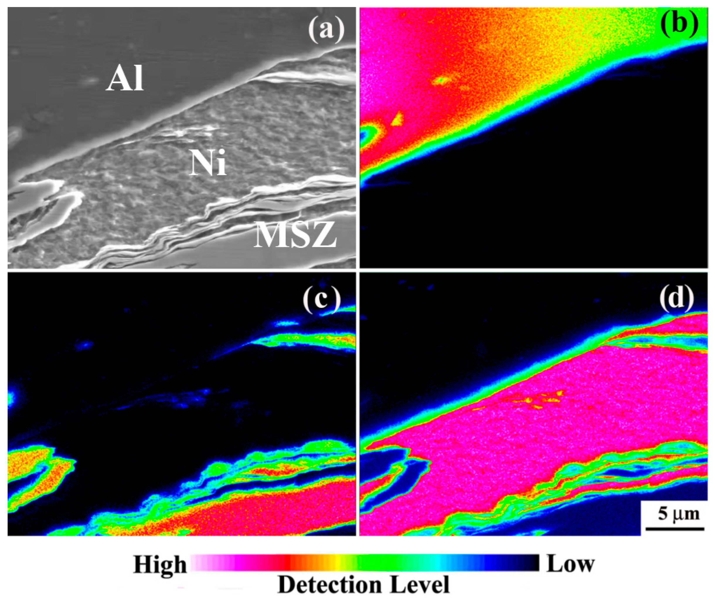
Figure 5 illustrates the elemental distribution of Al, Fe and Ni near the interface for process III, from the area shown in
Figure 3b. From
Figure 5, it was determined that the interface layer or the MSZ only contained Ni and Fe, and not Al. This implied that adding the Ni interlayer restricted the reaction between Al and Fe during FSLW. This is attributed to Ni having an FCC structure with a higher atom density of 0.74, which can effectively prohibit the diffusion of Fe into the Al alloy side. The atomic radius of Ni is relatively close to that of Fe, and thus at the Ni/steel interface, substitutional solid solution between Fe and Ni elements can be easily produced without the formation of Fe–Al compounds in the presence of heat during FSW. Furthermore, it has been reported that the Ni interlayer can control the liquid Fe/Al reaction process in the interfacial region by a formation of Al
0.9Ni
1.1 phase, thereby reducing the microhardness of the interfacial compound and improving the mechanical properties of the joint [
7]. Previous reports [
11,
12,
13,
14] indicated that the Zn interlayer can also improve the bonding interface between Al and steel. Given that Zn has a lower melting point, during FSW, the molten Zn interlayer diffused along the interface, extruding out the Al
2O
3 film and producing a strong interface. However, the Fe–Al compounds of Al
5Fe
2 and Al
13Fe
4 and a Zn-Al eutectic compound nucleated at the interface.
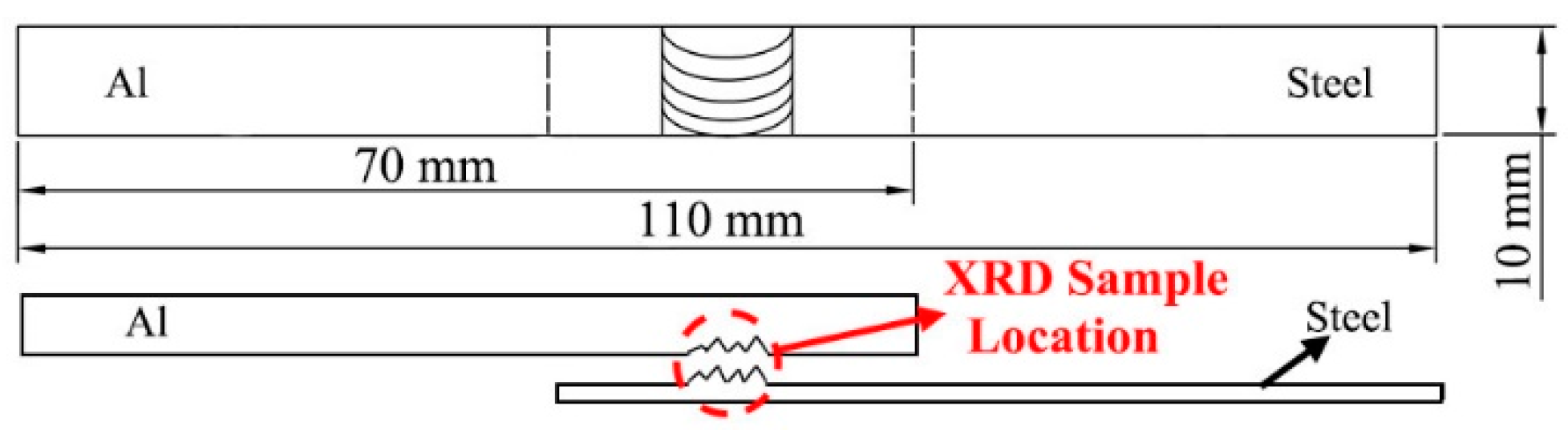
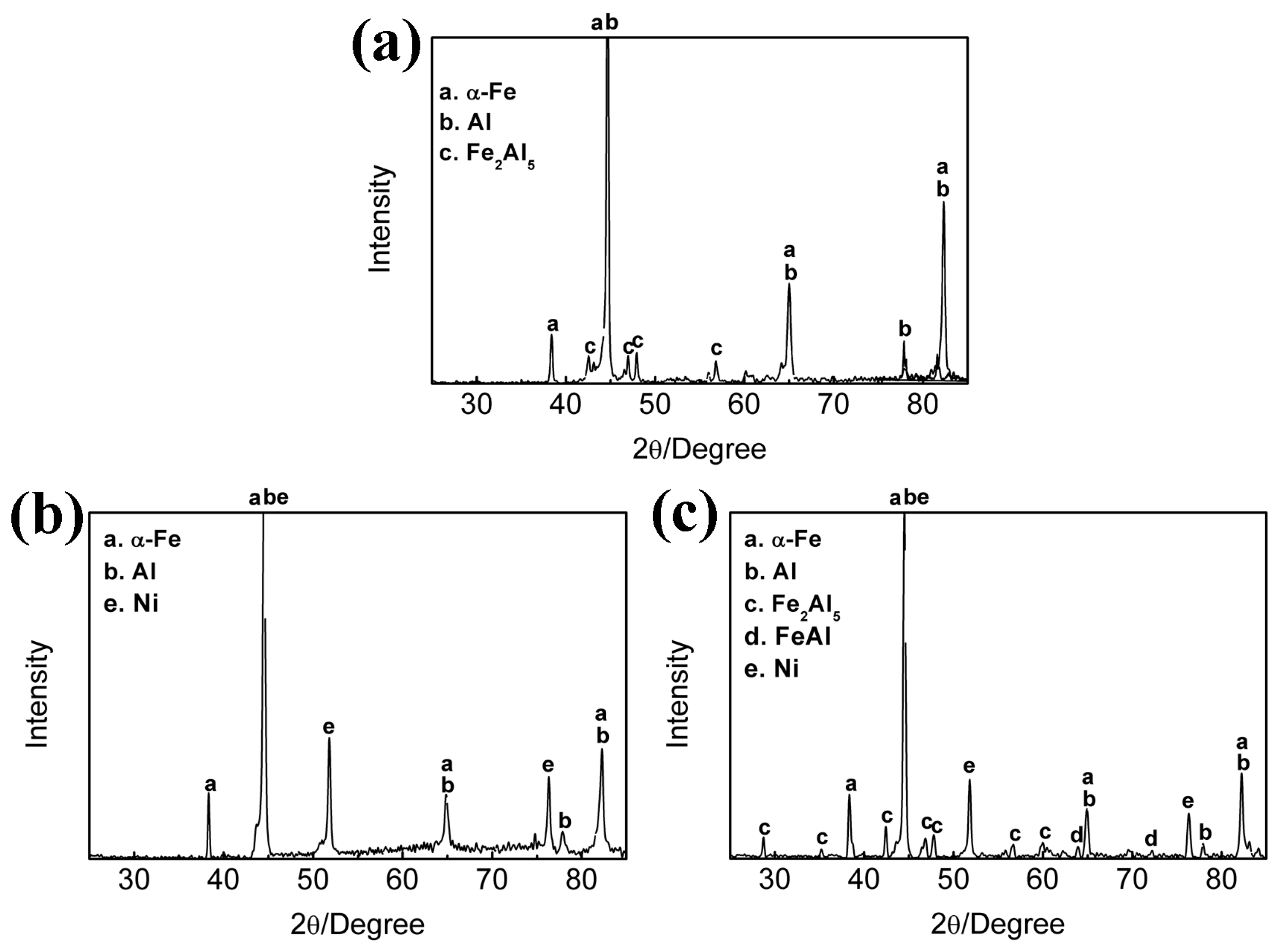
To further determine phase composition at the Al/steel interface, the XRD patterns at the interface for various processes were obtained and are presented in
Figure 6. From the XRD results (
Figure 6a), it was observed that for welds without a Ni interlayer, a diffraction peak of Fe
2Al
5 was detected in the vicinity of Fe and Al substrates. Combined with the EPMA results in
Table 3, it is clear that the interface layer and the MSZ comprised a Fe
2Al
5 phase and an alternating α-Fe solid solution and Fe
2Al
5 phase, respectively. This suggests that there was substantial diffusion of Fe to Al elements because of the formation of a stable Fe
2Al
5 intermetallic compound. By comparison, the weld with a Ni interlayer at a lower insertion depth of 0.07 mm only contained the diffraction peak of γ-Ni solid solution besides that of Al and steel substrates (
Figure 6b). Combining the EPMA results in
Table 3, it was concluded that this interface and the MSZ consisted of a γ-Ni solid solution and alternating α-Fe and γ-Ni solid solutions, respectively. This also further confirmed that the diffusion of Fe into Al was inhibited. However, when the insertion depth in the weld with a Ni interlayer was increased to 0.1 mm, two diffraction peaks of Fe
2Al
5 and FeAl phases were detected at the Al/steel interface besides γ-Ni and α-Fe solid solutions, and Al substrate (
Figure 6c). Combining those results with
Table 3, the interface was determined to consist of FeAl and Fe
2Al
5 compound phases, and the MSZ consisted of α-Fe and γ-Ni solid solutions. With increased insertion depth, the interface layer of the γ-Ni solid solution was shifted by intermetallic compounds of both FeAl and Fe
2Al
5. This is attributed to the fact that the increased insertion depth resulted in increases in heat input and stirring degree within the weld, thereby leading to the mixing of the Ni interlayer with the MSZ. The inhibiting action of the Ni interlayer became weak, and the partial diffusion of Fe into the Al side produced a small amount of Fe–Al compound at the interface. However, the diffusion was not substantial, and thus a metastable FeAl intermetallic compound with a lower Al content was obtained in addition to the Fe
2Al
5 phase. By comparison, although the Fe–Al compounds are obviously inhibited by inserting a Ni interlayer in the laser welded Fe/Al joint, a new Ni-Al phase was detected, which may be attributed to the higher heat input of laser welding [
7].
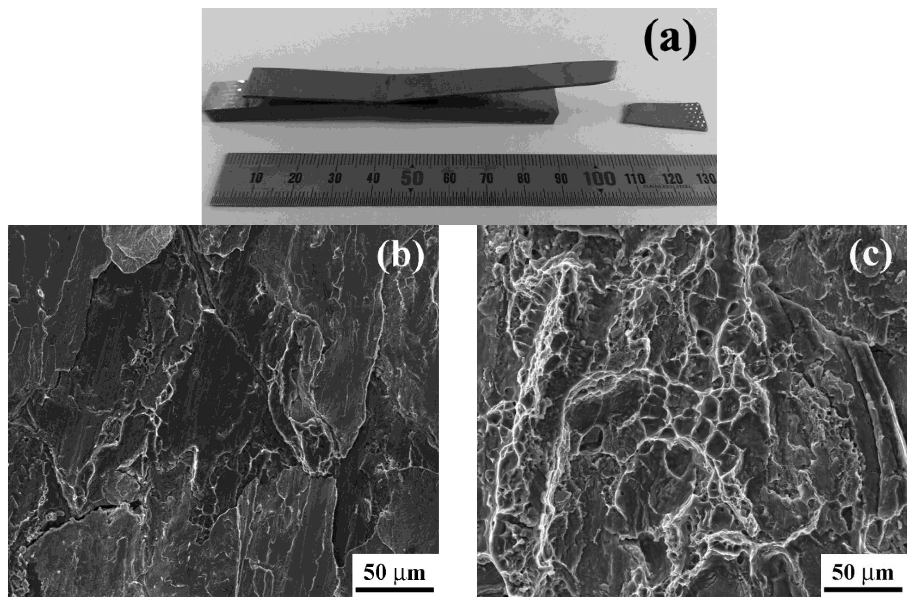
Table 2 presents tensile-shear fracture loads of the Al/steel joints. First, with an increase in the insertion depth, the fracture load of the weld without the Ni interlayer was gradually decreased. This can be mainly attributed to the formation of more Fe–Al intermetallic compounds at the interface and the MSZ (
Figure 4b), such that brittle fracture with a number of cleavage facets occurred (
Figure 7b). Second, for the weld containing the Ni interlayer at the insertion depth of 0.07 mm, a maximum fracture load of 4.3 kN was obtained, with fracturing occurring at the steel substrate away from the Al/steel interface (
Figure 7a). This suggested that the Ni interlayer can lead to significant enhancements in mechanical properties, which are associated with the disappearance of the Fe–Al intermetallic compound about the interface. In fact, the interface layer and the MSZ comprised a γ-Ni solid solution, and both α-Fe and γ-Ni solid solutions, which exhibited good strength and toughness, thereby leading to ductile fracture in the steel substrate. Third, with an increase in the insertion depth, the fracture load of the weld containing the Ni interlayer started to decrease. This originated from the Fe–Al intermetallic compounds formed at the Al/steel interface, reducing the tensile-shear fracture load of the weld. Nevertheless, this fracture load was also superior to that of the weld without the Ni interlayer (
Table 2), and a mixed fracture mode (ductile and brittle) was detected in
Figure 7c with dimples and cleavage facets. This was derived from the formation of a meta-stable FeAl intermetallic compound, which was identified to have relatively sound ductility due to the lower Al contents in a series of Fe–Al intermetallic compounds by previous reports [
9]. Thus, it was detected that by controlling the type of Fe–Al intermetallic compound at the Fe/Al interface, the mechanical properties of the joint can be improved to some extent.
The previous studies indicated that whether improving the FSW process or adding the coating on the steel surface, the hard and brittle Fe–Al intermetallic compounds still emerged at the Al/steel interface, which were potential sites for crack initiation [
11,
12,
13,
14,
15]. In our study, the Ni interlayer effectively inhibited the formation of Fe–Al intermetallic compounds, leading to significant improvements in the bonding properties of the Al/steel interface.


