
Precipitation Behaviors of Carbides in High Speed Steel during ESR and Heat Treatment


Abstract
:1. Introduction
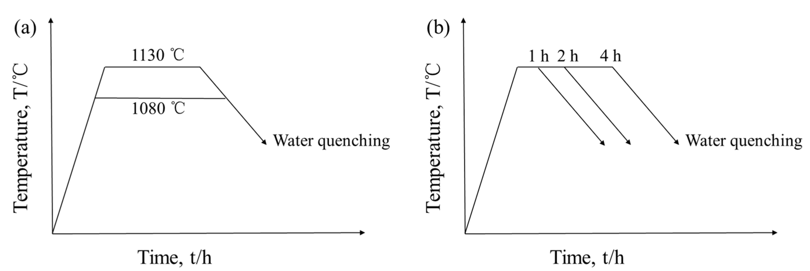
2. Materials and Methods
3. Results and Discussion
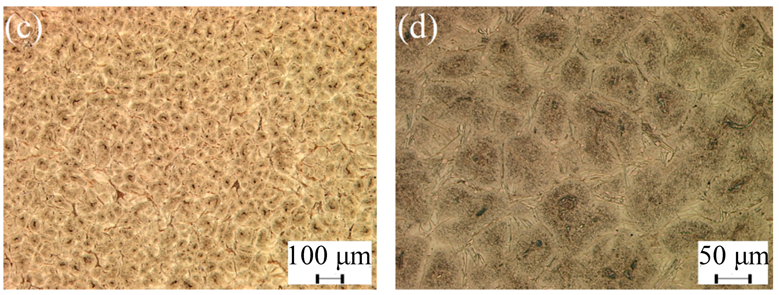
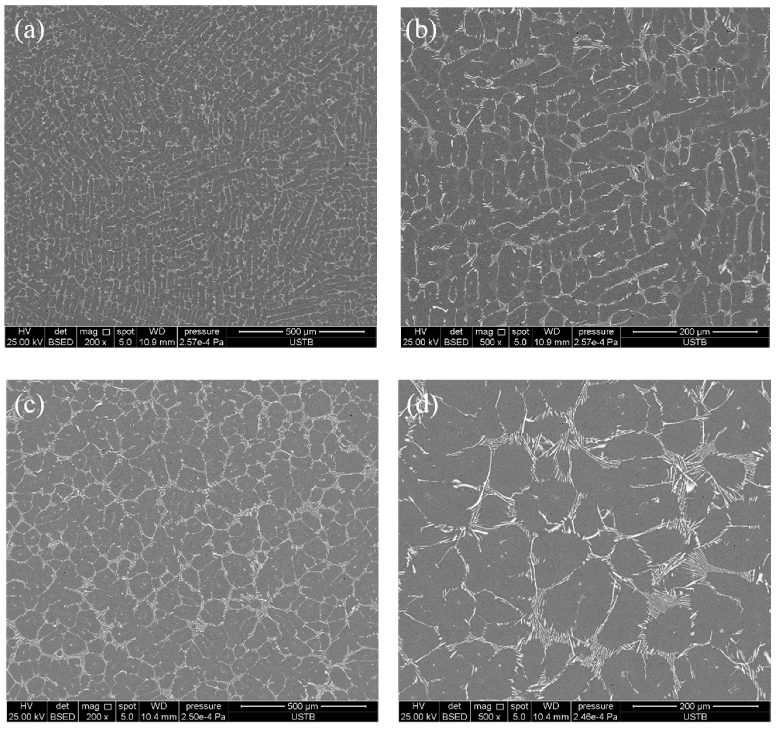
3.1. Microstructure of As-Cast and ESR Ingot
3.2. Phases Formation Calculated with Thermo-Calc Software
3.3. Effect of Heat Treatment on Carbide Evolution
4. Conclusions
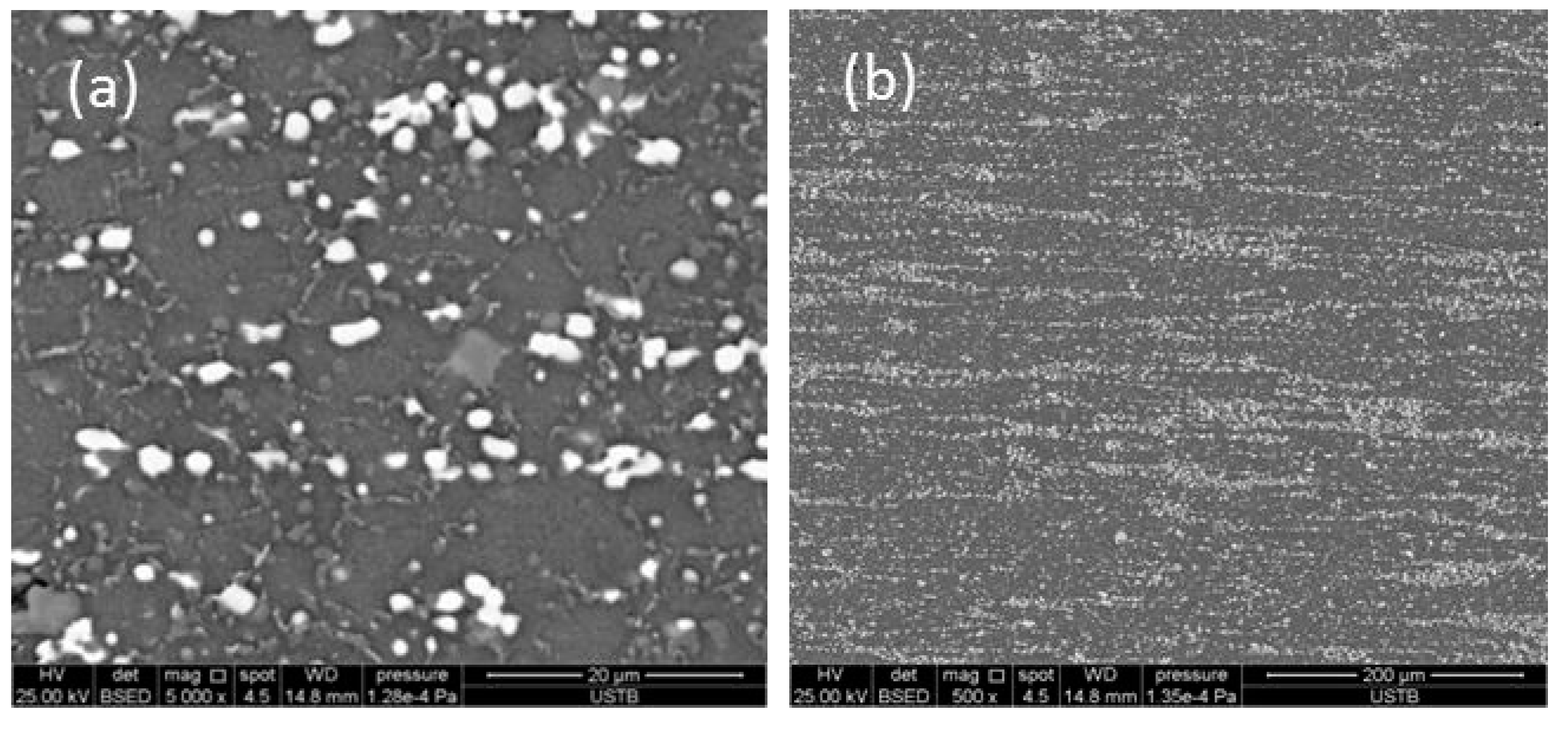
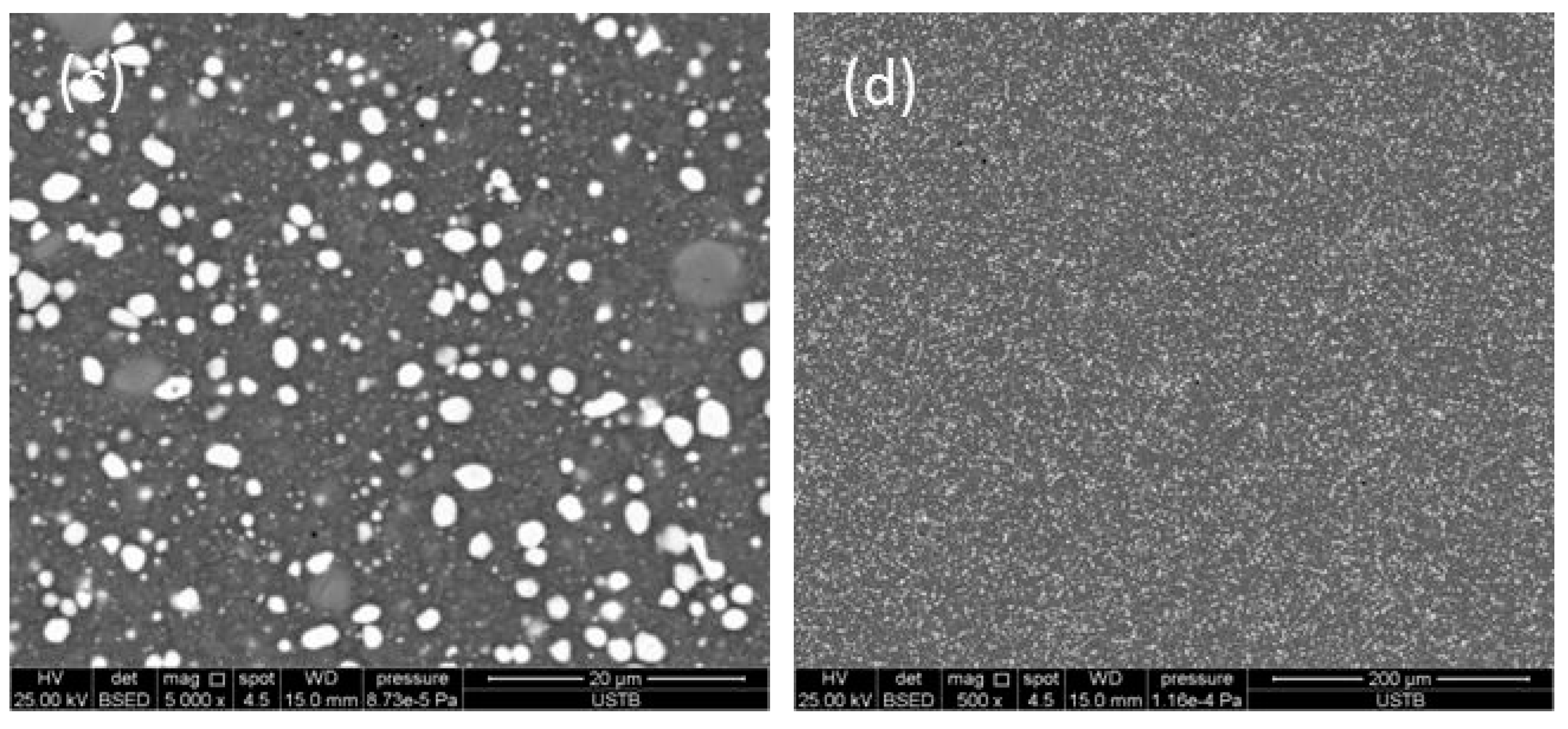
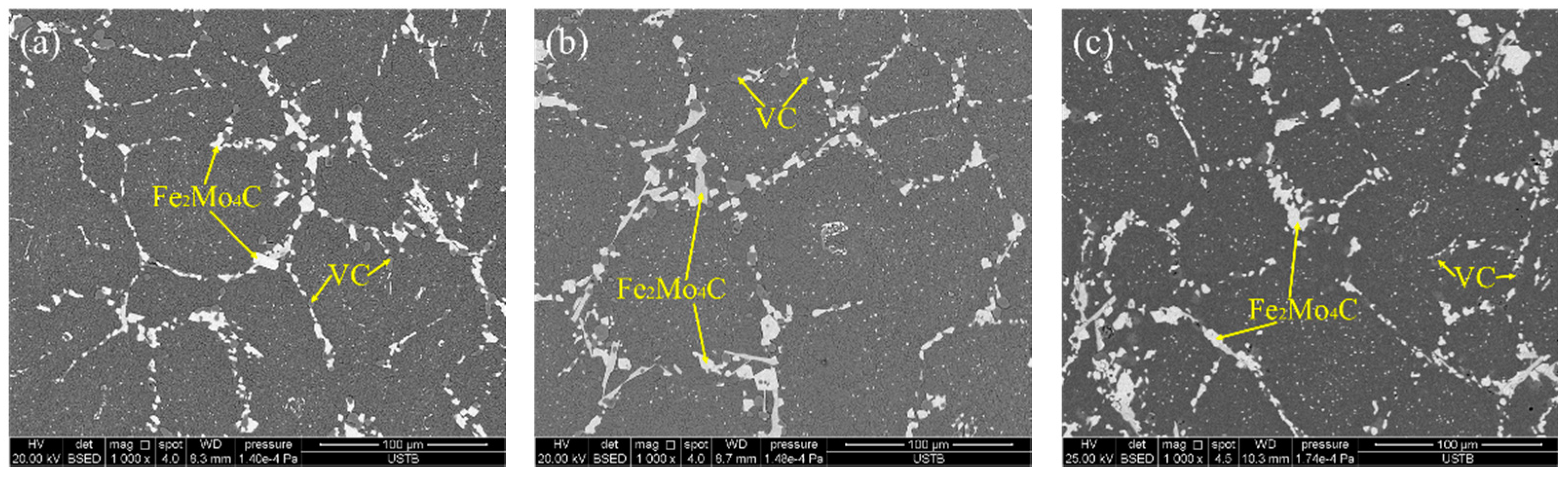
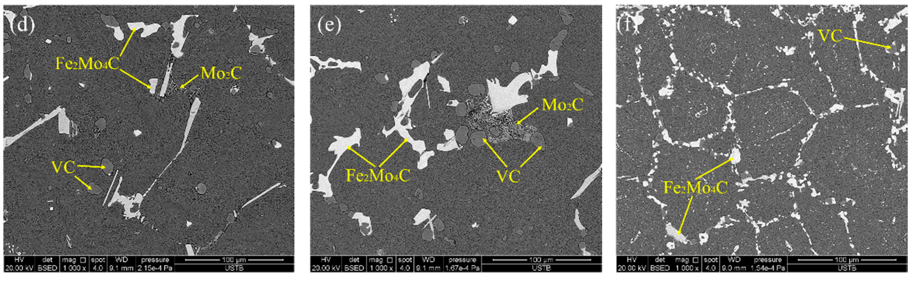
- The carbides of high-speed steel after electroslag remelting are of a large size and mainly lamellar and fibrous precipitates along the grain boundary. After solution treatment, the size of carbides is obviously reduced and the distribution of carbides are uniform, and the morphology of carbides are mainly short-rod, irregular spherical, and fine particles.
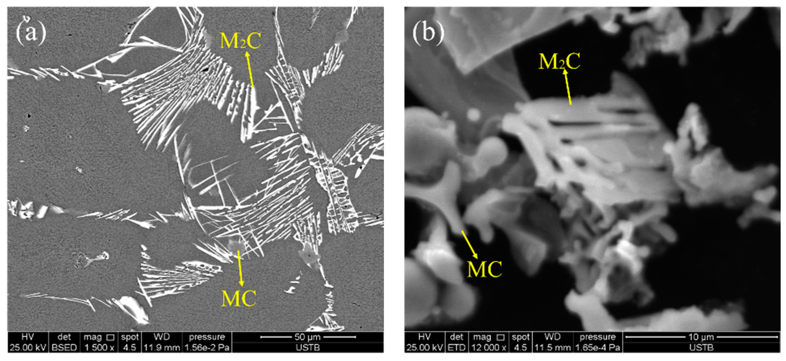
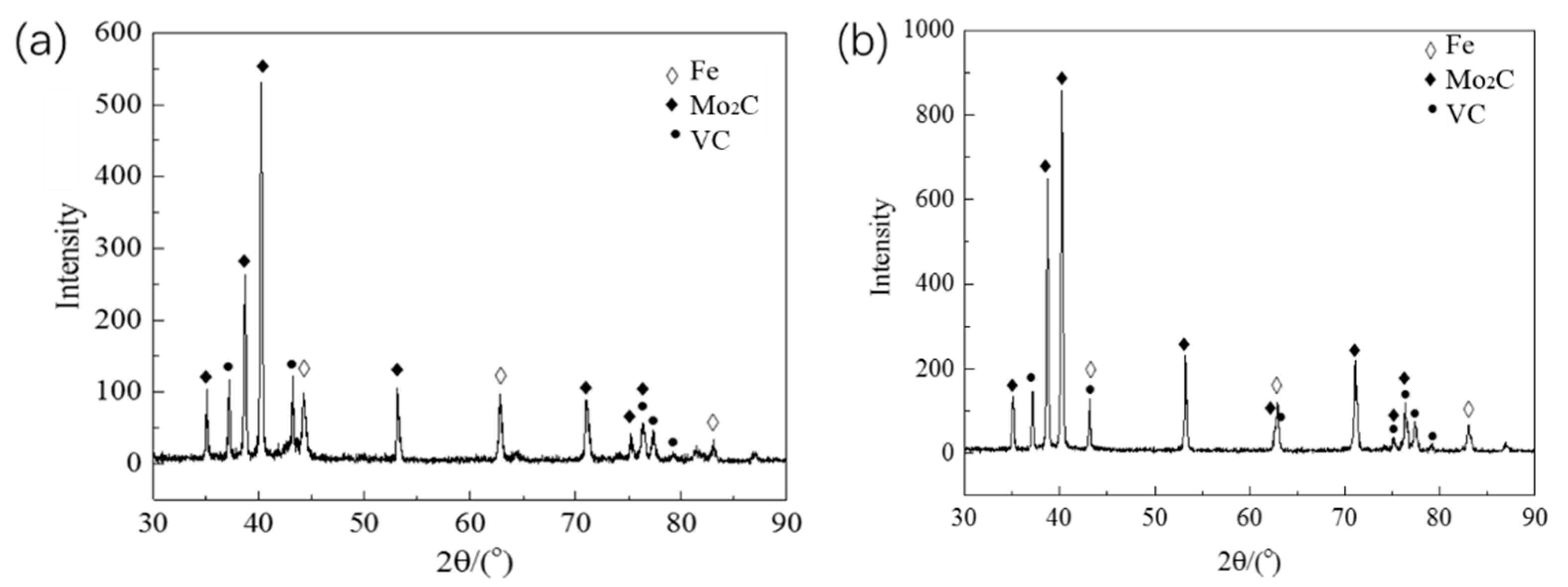
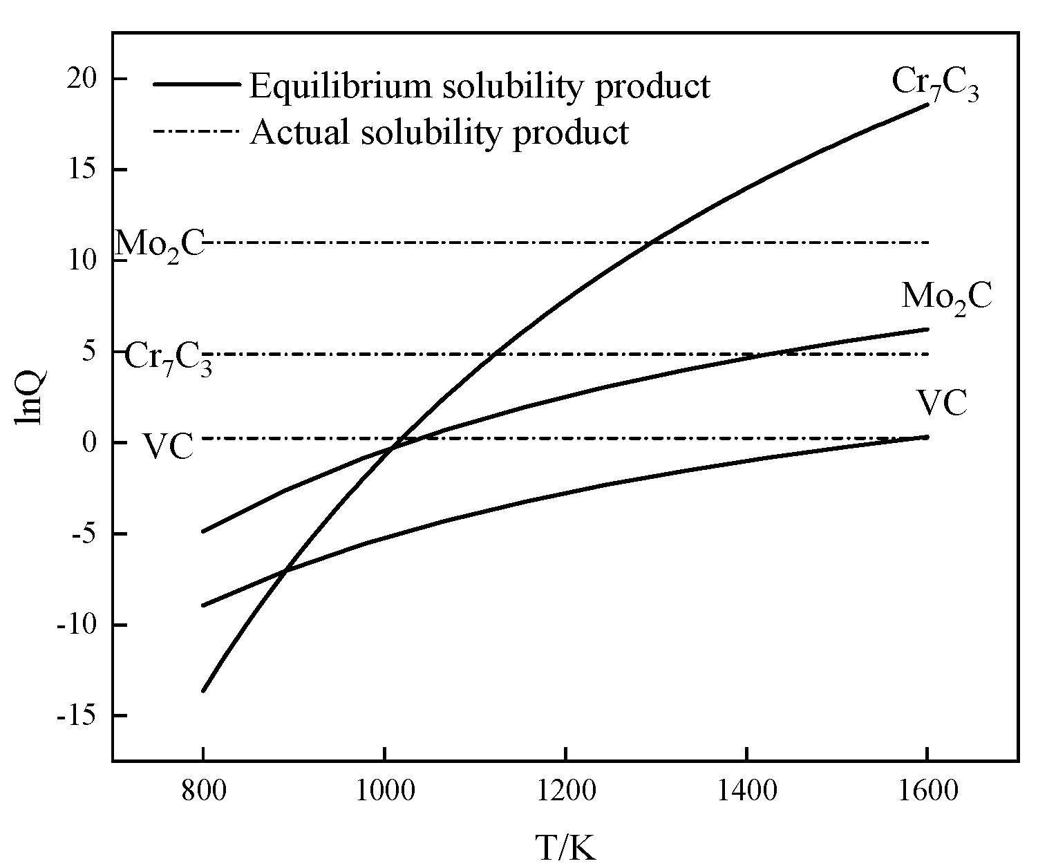
- The carbide types both in as-cast and ESR high-speed steel are metastable carbides Mo2C and VC. The types of carbides after solution treatment, forging, and hot rolling are mainly small composite carbides containing molybdenum, vanadium, and chromium, including Mo6C, VC, and Cr7C3. Mo2C carbides in ESR ingot can be decomposed into VC and Fe2Mo4C during the solution treatment.
- After forging and hot rolling, carbides are completely spheroidal and dispersed in the matrix. The average diameter of the carbides can be reduced to 1.28 μm and the space distance reduced to 3.23 μm. A uniform distribution of spheroidal shaped carbides was achieved.
Author Contributions
Funding
Data Availability Statement
Conflicts of Interest
References
- Sano, Y.; Hattori, T.; Haga, M. Characteristics of high-carbon high speed steel rolls for hot strip mill. ISIJ Int. 1992, 32, 1194–1201. [Google Scholar] [CrossRef]
- Chu, W.; Xie, C.; Wu, X.C. Research on controlling eutectic carbides in M2 high speed steel of ESR process. Shanghai Met. 2013, 25, 23–26+62. (In Chinese) [Google Scholar]
- Zhou, X.F.; Fang, F.; Li, F.; Jiang, J.Q. Morphology and microstructure of M2C carbide formed at different cooling rates in AIST M2 high speed steel. J. Mater. Sci. 2011, 46, 1196–1202. [Google Scholar] [CrossRef]
- Mattar, T.; Ibrahim, K.M.; Fathy, A.; Faramawy, H.E. Improving the wear resistance of M41 steel by nitrogen alloying and ESR. Mater. Charact. 2007, 58, 407–415. [Google Scholar] [CrossRef]
- Kim, C.K.; Park, J.I.; Lee, S.; Kim, Y.C.; Yang, N.J. Effects of alloying elements on microstructure, hardness, and fracture toughness of centrifugally cast high-speed steel rolls. Metall. Mater. Trams. A 2005, 36, 87–97. [Google Scholar] [CrossRef] [Green Version]
- Deng, Y.K.; Chen, J.R.; Wang, S.Z. High Speed Tool Steel; Guo, G.C., Ed.; Metallurgical Industry Press: Beijing, China, 2002; pp. 199–200. [Google Scholar]
- Zhou, X.F.; Zhu, W.L.; Jiang, H.B.; Fang, F.; Tu, Y.Y.; Jiang, J.Q. A new approach for refining carbide dimensions in M42 super hard high-speed steel. J. Iron Steel Res. Int. 2016, 23, 800–807. [Google Scholar] [CrossRef]
- Rodenburg, C.; Rainforth, W.M. A quantitative analysis of the influence of carbides size distributions on wear behavior of high-speed steel in dry rolling/sliding contact. Acta Mater. 2007, 55, 2443–2454. [Google Scholar] [CrossRef]
- Zhu, Q.; Zhu, H.T.; Tieu, A.K.; Reid, M.; Zhang, L.C. In-situ investigation of oxidation behavior in high-speed steel roll material under dry and humid atmospheres. Corros. Sci. 2010, 52, 2707–2715. [Google Scholar] [CrossRef]
- Gill, S.S.; Singh, J.; Singh, R.; Singh, H. Effect of cryogenic treatment on AIST M2 high speed steel: Metallurgical and mechanical characterization. J. Mater. Eng. Perform. 2012, 21, 1320–1326. [Google Scholar] [CrossRef]
- Kou, G.F.; Yan, X.G.; Liang, Y.; Li, J.J.; Chen, Y.H.; Fu, J.W.; Cao, Q.C. Effect of cryogenic temperature on abrasion performance of W6Mo5Cr4V2 high speed steel. Trans. Mater. Heat Treat. 2016, 37, 39–43. (In Chinese) [Google Scholar]
- Lei, L.J.; Jia, F.; Qin, C. Origin of square segregation in high speed steel tool steel bars in electroslag refining. Heibei Metall. 1998, Z1, 52–54+143. (In Chinese) [Google Scholar]
- Shi, C.B.; Chen, X.C.; Guo, H.J.; Zhu, Z.J.; Sun, X.L. Control of MgO·Al2O3 spinel inclusions during protective gas electroslag remelting of die steel. Metall. Mater. Trans. B 2013, 44, 378–389. [Google Scholar] [CrossRef]
- Shu, S.H.; Choi, J. Effect of melting rate on the carbide cell size in an electroslag remelted high speed steel ingot. ISIJ Int. 1986, 26, 305–309. [Google Scholar]
- Ma, D.X.; Grafe, U. Microstructure in directionally solidified dendritic-cellular structure of superalloy CMSX-4. Mater. Sci. Eng. A 1999, 2, 339–342. [Google Scholar] [CrossRef]
- Lenta, E.J.; Twentyman, M.E.; Pesci, H. Transformation of the primary carbide networks in high-speed steels by heat treatment at high temperatures. Metallography 1983, 16, 387–401. [Google Scholar] [CrossRef]
- Fu, R.; Li, F.L.; Yin, F.J.; Feng, D.; Tian, Z.L.; Chang, L.T. Microstructure evolution and deformation mechanisms of the electroslag refined-continuous directionally solidified (ESR-CDS) superalloy Rene88DT during isothermal compression. Mater. Sci. Eng. A 2015, 638, 152–164. [Google Scholar] [CrossRef]
- Zhou, X.F.; Fang, F.; Li, F.; Jiang, J.Q. Study on property and morphology of M2C eutectic carbides in M2 high speed steel. Iron Steel 2009, 9, 76–80. (In Chinese) [Google Scholar]
- Qi, Y.F.; Li, J.; Shi, C.B.; Zhang, Y.; Zhu, Q.T.; Wang, H. Effect of directional solidification of electroslag remelting on the microstructure and primary carbides in an austenitic hot-work die steel. J. Mater. Process. Technol. 2017, 249, 32–38. [Google Scholar] [CrossRef]
- Li, X.W.; Wang, L.; Dong, J.S.; Lou, L.H. Effect of solidification condition and carbon content on the morphology of MC carbide in directional solidified Nickel-base superalloys. J. Mater. Sci. Technol. 2014, 30, 1296–1300. [Google Scholar] [CrossRef]
- Qi, Y.F.; Li, J.; Shi, C.B. Characterization on microstructure and carbides in an austenitic hot-work die steel during ESR solidification process. ISIJ Int. 2018, 58, 2079–2087. [Google Scholar] [CrossRef] [Green Version]
- Halfa, H.; Eissa, M.; EI-Fawakhry, K.; Mattar, T. Effect of nitrogen and niobium on the structure and secondary hardening of super hard high speed tool steel. Steel Res. Int. 2012, 83, 32–42. [Google Scholar] [CrossRef]
- Lee, E.S.; Park, W.J.; Jung, J.Y.; Ahn, S. Solidification microstructure and M2C carbide decomposition in a spray-formed high-speed steel. Metal. Mater. Trans. A 1998, 29, 1395–1404. [Google Scholar] [CrossRef]
- Luo, Y.W.; Guo, H.J.; Sun, X.L. Precipitation behaviors of carbides in M42 high speed steel during ESR and forging. Iron Steel 2017, 52, 68–75. (In Chinese) [Google Scholar]


| C | W | Mo | Cr | V | Si | Mn | Y | Fe |
|---|---|---|---|---|---|---|---|---|
| 1.2 | 3.5 | 8.2 | 3.9 | 2.8 | 0.62 | 0.3 | 0.03 | Bal. |
| Specimen Number | Solution Treatment Temperature | Solution Treatment Time |
|---|---|---|
| 1080-1 | 1080 °C | 1 h |
| 1080-2 | 2 h | |
| 1080-4 | 4 h | |
| 1130-1 | 1130 °C | 1 h |
| 1130-2 | 2 h | |
| 1130-4 | 4 h |
| Ts/°C | Tf/°C | |||||
|---|---|---|---|---|---|---|
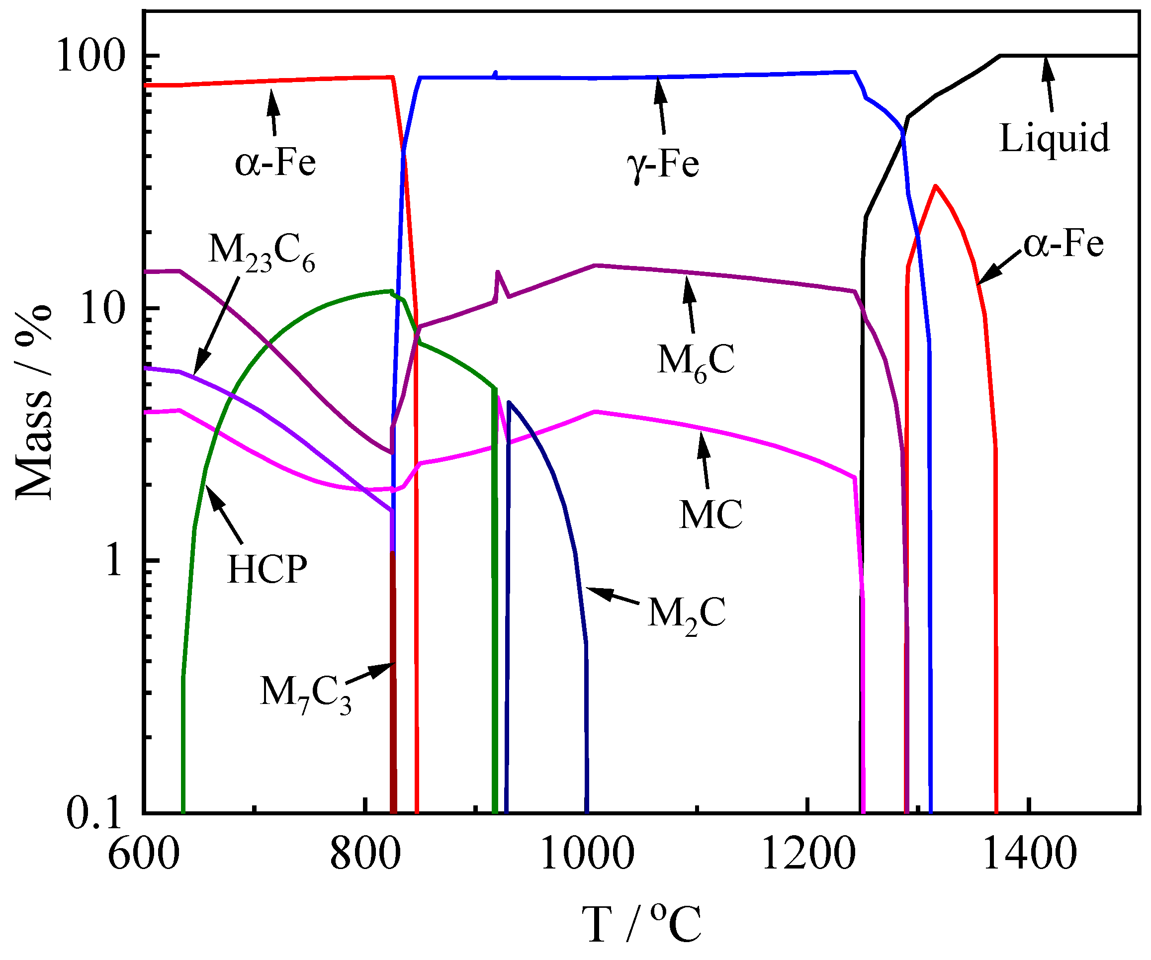
| M6C | MC | M2C | M7C3 | M23C6 | M2C | M7C3 |
| 1290 | 1250 | 1000 | 826 | 824 | 920 | 824 |
| Reaction | Ts/°C | fs |
|---|---|---|
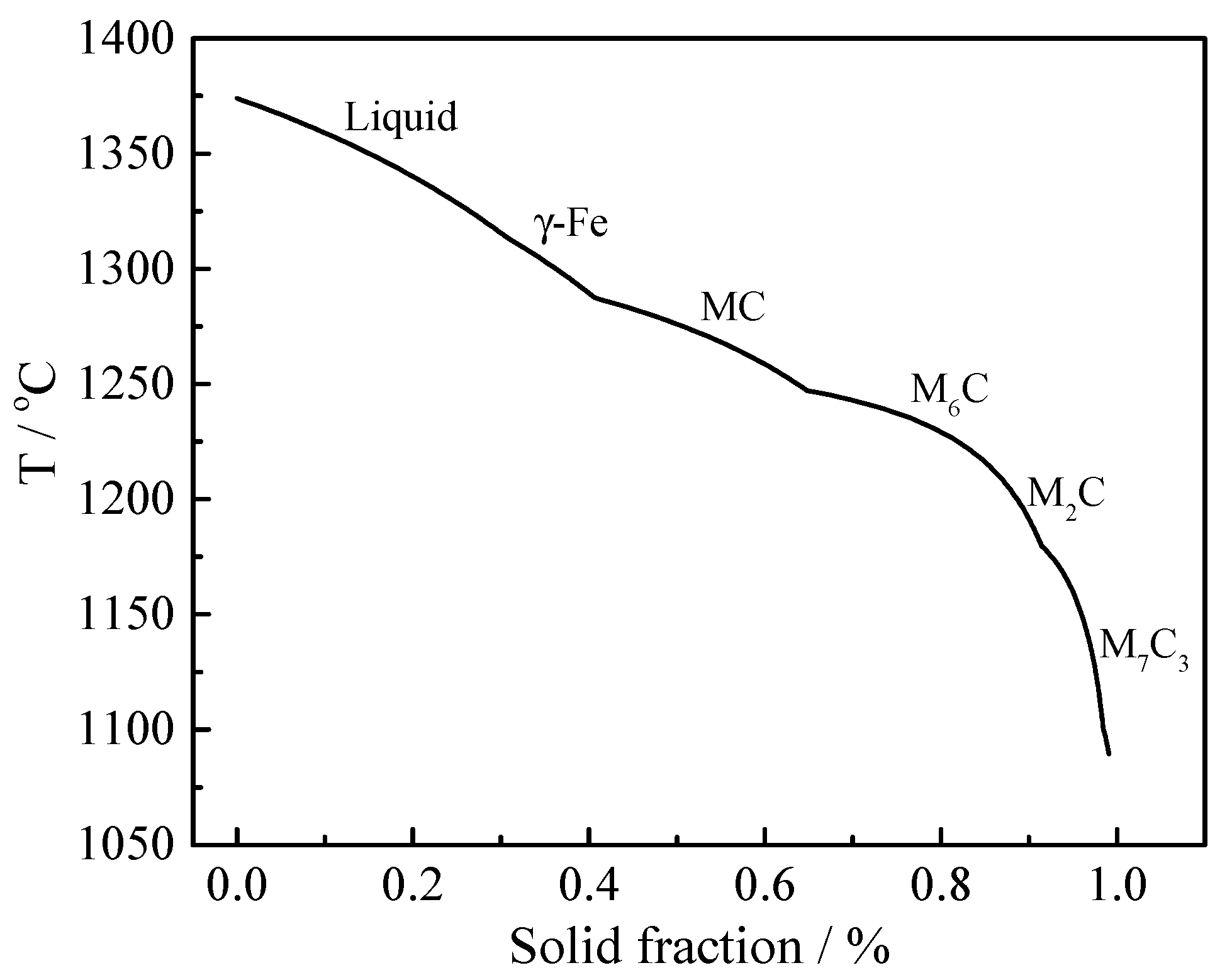
| L → γ-Fe + MC | 1287 | 0.4 |
| L → γ-Fe + MC + M6C | 1245 | 0.65 |
| L → γ-Fe + MC + M6C + M2C | 1219 | 0.84 |
| L → γ-Fe + MC + M6C + M2C + M7C3 | 1180 | 0.9 |
| Relation Formula | Unit | Spatial Characteristic Parameter |
|---|---|---|
| VV = AA | % | Volume fraction of carbide |
| NV = NA/ | -- | Number of carbides in per unit volume |
| μm | Space distance of carbide |
| Status | Basic Parameters | Characteristic Parameters | ||||
|---|---|---|---|---|---|---|
| NA | A/μm2 | /μm | VV/% | NV | t0/μm | |
| ESR | 1671 | 5491 | 3.84 | 7.06 | 5.60 × 10⁻³ | 13.37 |
| Hot-rolling | 2334 | 1817 | 1.28 | 9.54 | 9.57× 10⁻² | 3.23 |
| Solution treatment | 522 | 7706 | 5.03 | 9.90 | 1.33 × 10⁻³ | 27.39 |
Publisher’s Note: MDPI stays neutral with regard to jurisdictional claims in published maps and institutional affiliations. |
© 2021 by the authors. Licensee MDPI, Basel, Switzerland. This article is an open access article distributed under the terms and conditions of the Creative Commons Attribution (CC BY) license (https://creativecommons.org/licenses/by/4.0/).
Share and Cite
Liu, Y.; Li, J.; Liang, W.; Gao, J.; Qi, Y.; Shang, C. Precipitation Behaviors of Carbides in High Speed Steel during ESR and Heat Treatment. Metals 2021, 11, 1781. https://doi.org/10.3390/met11111781
Liu Y, Li J, Liang W, Gao J, Qi Y, Shang C. Precipitation Behaviors of Carbides in High Speed Steel during ESR and Heat Treatment. Metals. 2021; 11(11):1781. https://doi.org/10.3390/met11111781
Chicago/Turabian StyleLiu, Yang, Jing Li, Wei Liang, Jiawei Gao, Yongfeng Qi, and Chengjia Shang. 2021. "Precipitation Behaviors of Carbides in High Speed Steel during ESR and Heat Treatment" Metals 11, no. 11: 1781. https://doi.org/10.3390/met11111781
APA StyleLiu, Y., Li, J., Liang, W., Gao, J., Qi, Y., & Shang, C. (2021). Precipitation Behaviors of Carbides in High Speed Steel during ESR and Heat Treatment. Metals, 11(11), 1781. https://doi.org/10.3390/met11111781