
Impact of Laser Texturing on Ni-Based Single Crystal Superalloys

 ,
,
Abstract
:1. Introduction
2. Materials and Methods
2.1. Materials and Heat Treatments
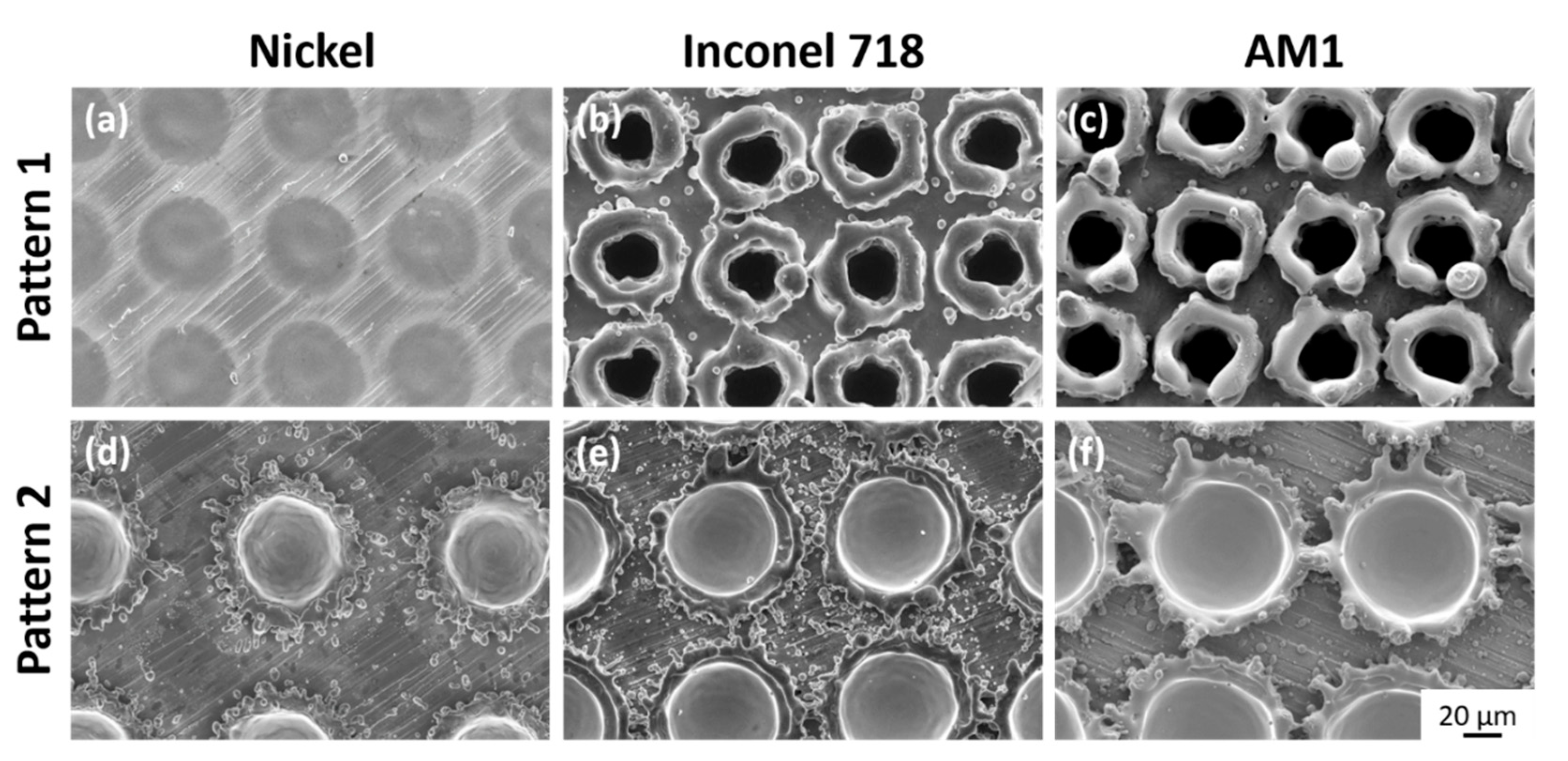
2.2. Laser Surface Treatments
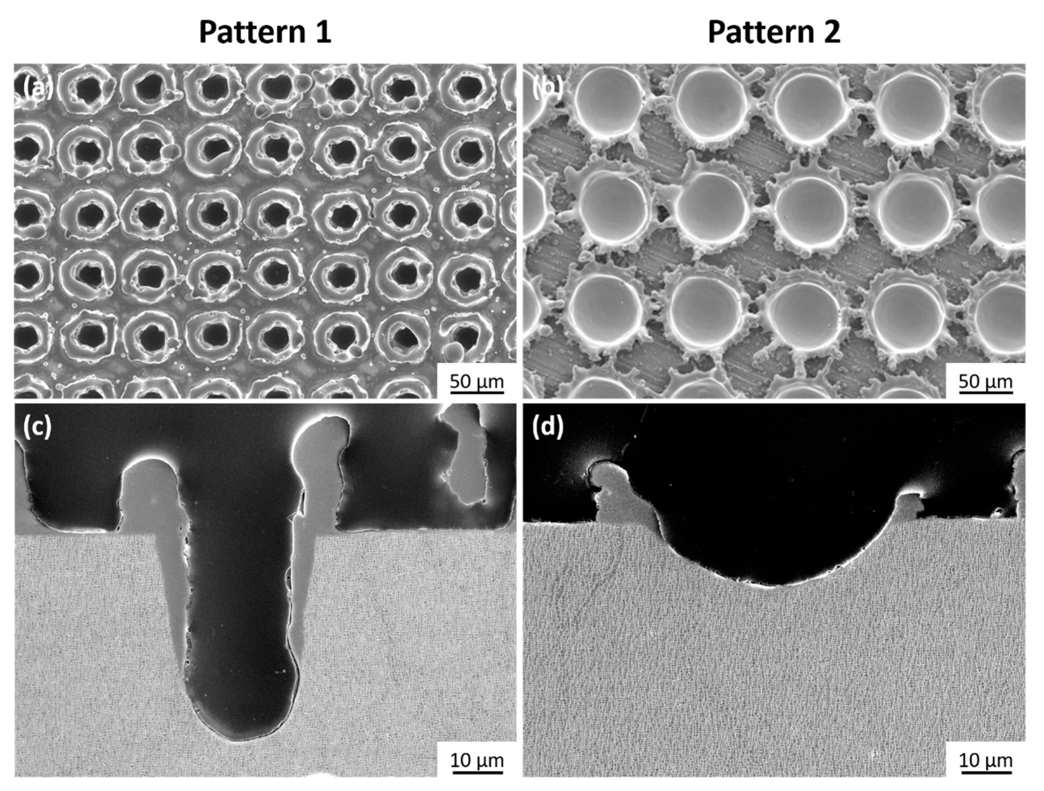
- “Pattern 1”, formed by holes spaced 60 μm apart generated by 50 pulses at a laser intensity of 8.8.10−2 GW/cm2.
- “Pattern 2”, formed by holes spaced 100 μm apart generated by 15 pulses at a laser intensity of 1.8.10−1 GW/cm2.
2.3. Characterization Methods
3. Results
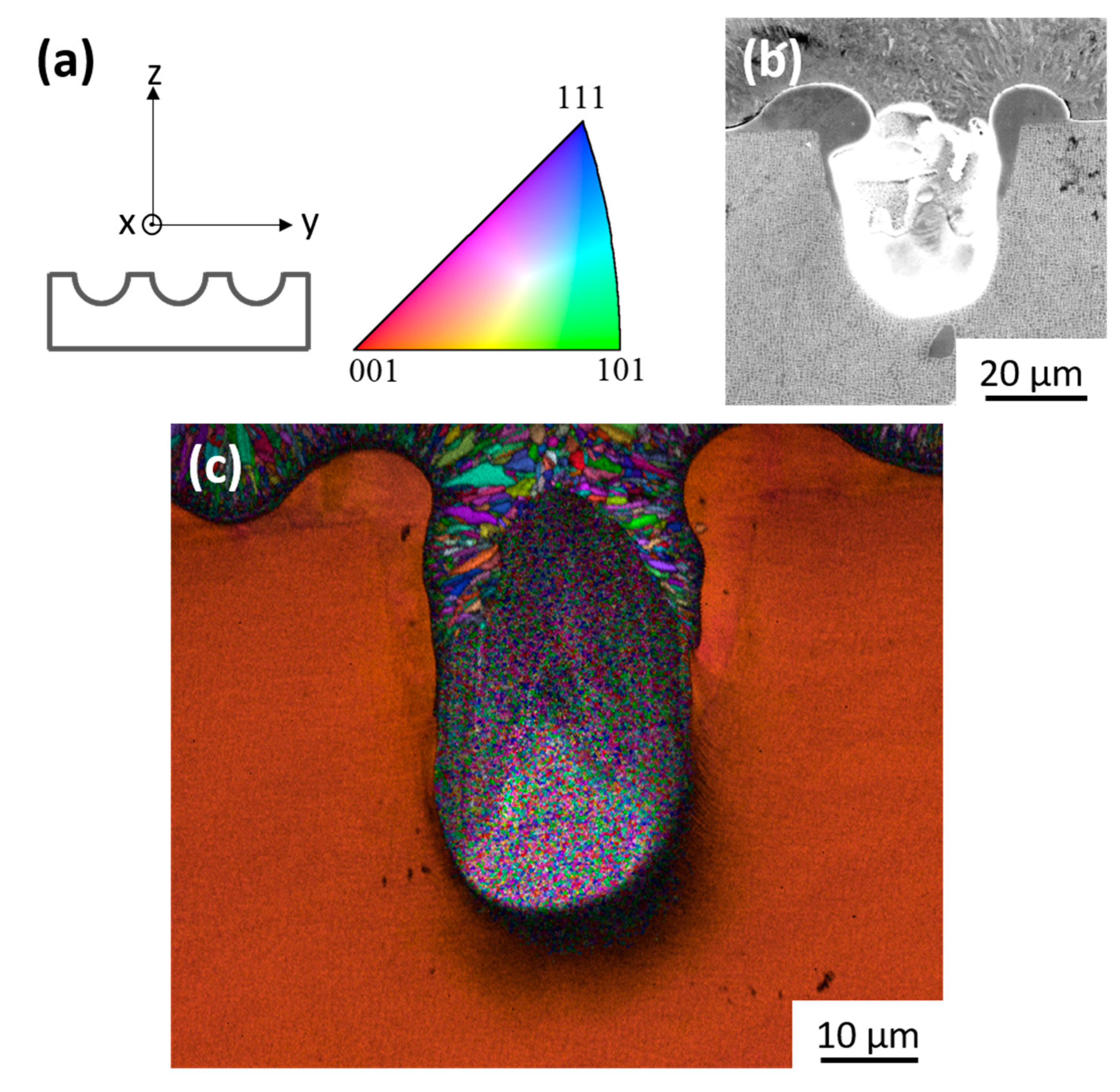
3.1. Microstructural Evolutions Close to the Textured Patterns
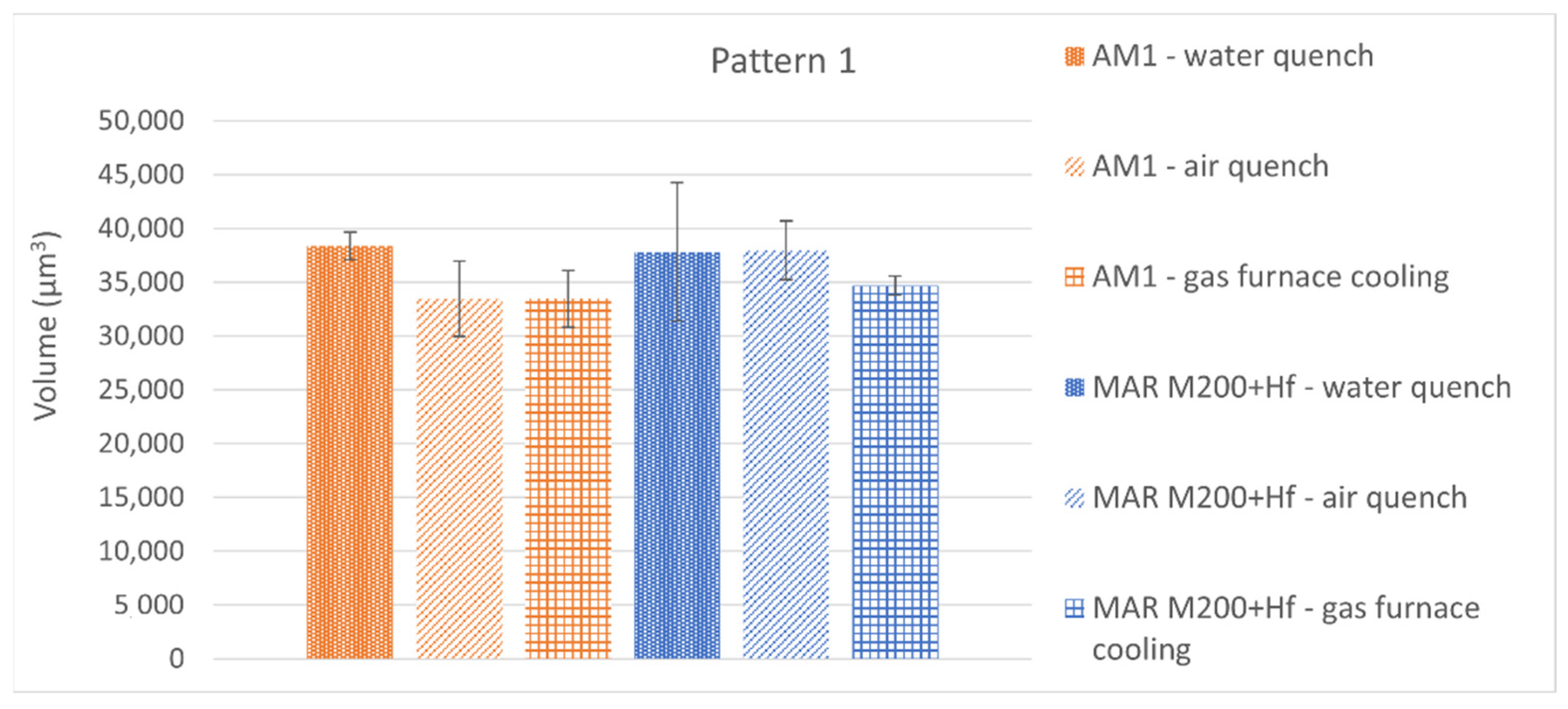
3.2. Comparison of Thermally Affected Volumes
4. Discussion
5. Conclusions
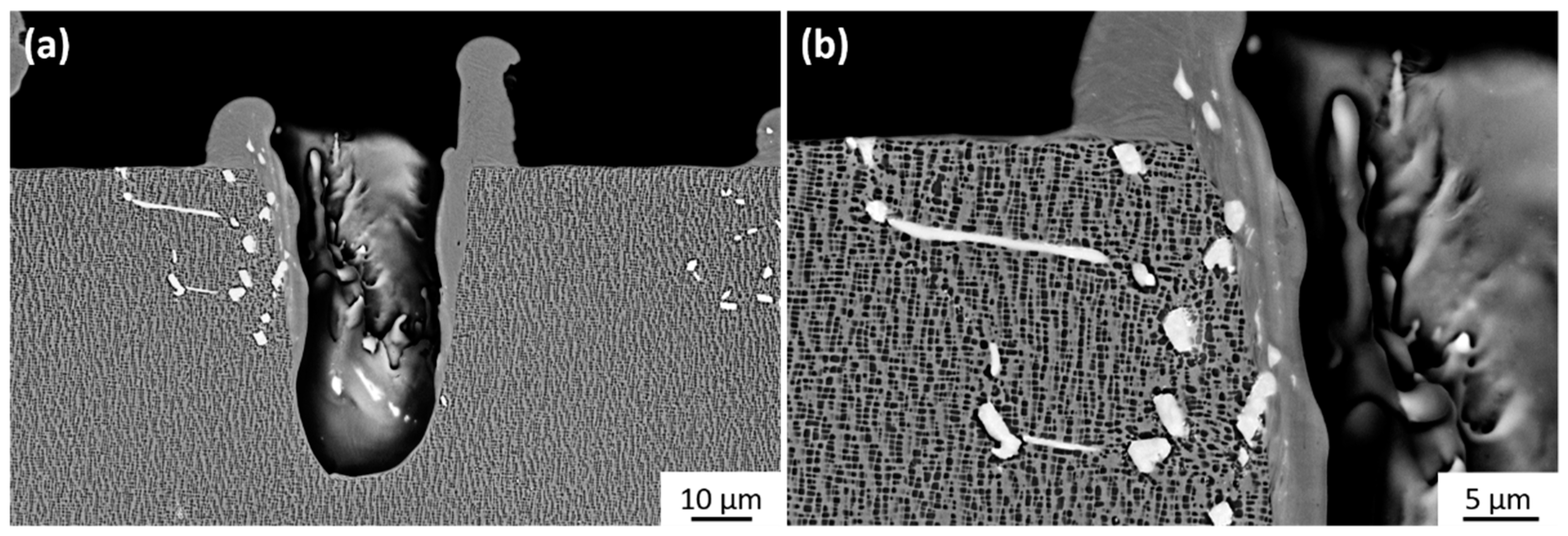
- Infrared nanosecond laser ablation promotes the formation of asperities composed of melted, re-solidified matter around cavities. The microstructure within the asperities is clearly different from the core of superalloys. The standard γ/γ′ morphology cannot be observed.
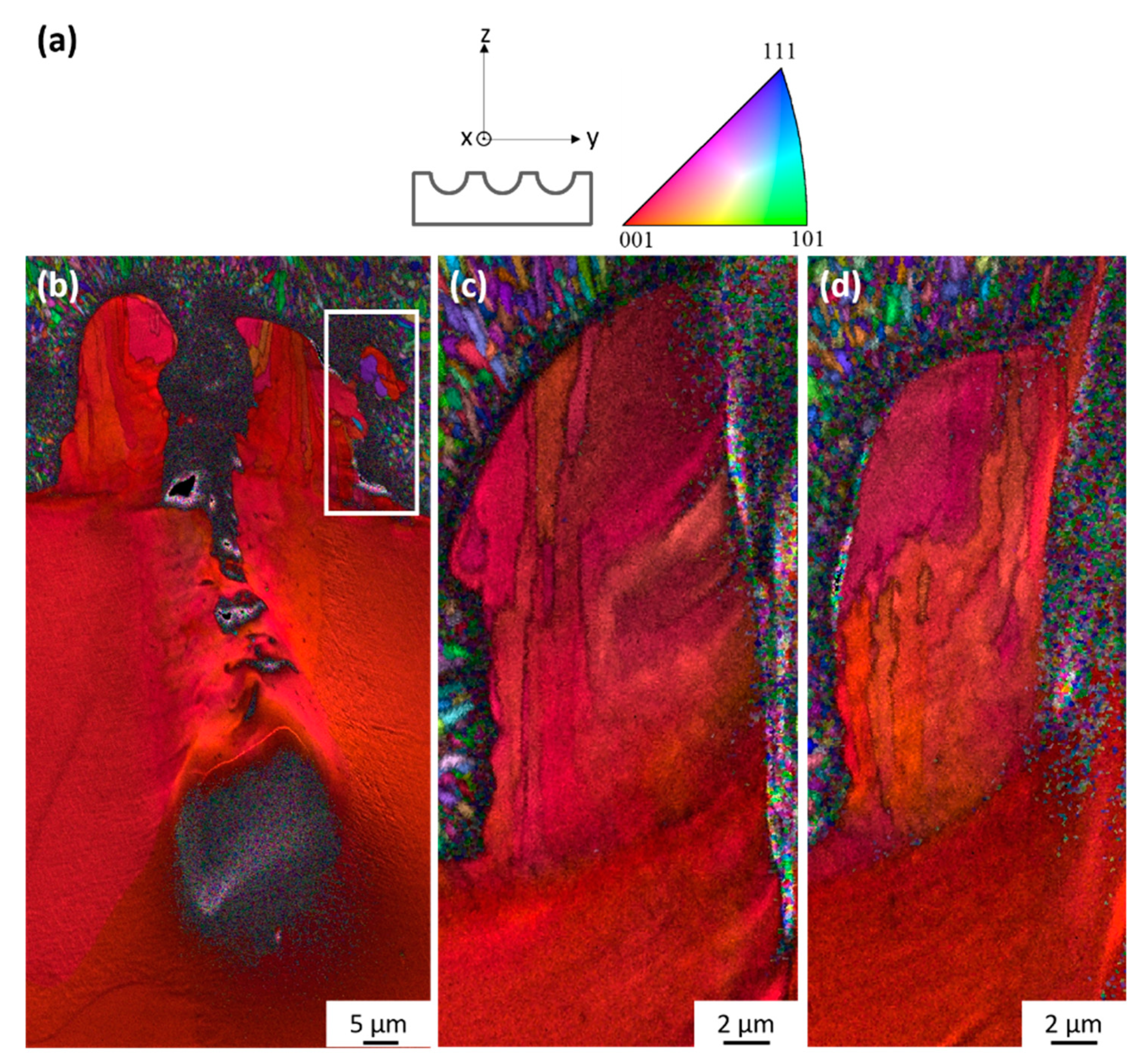
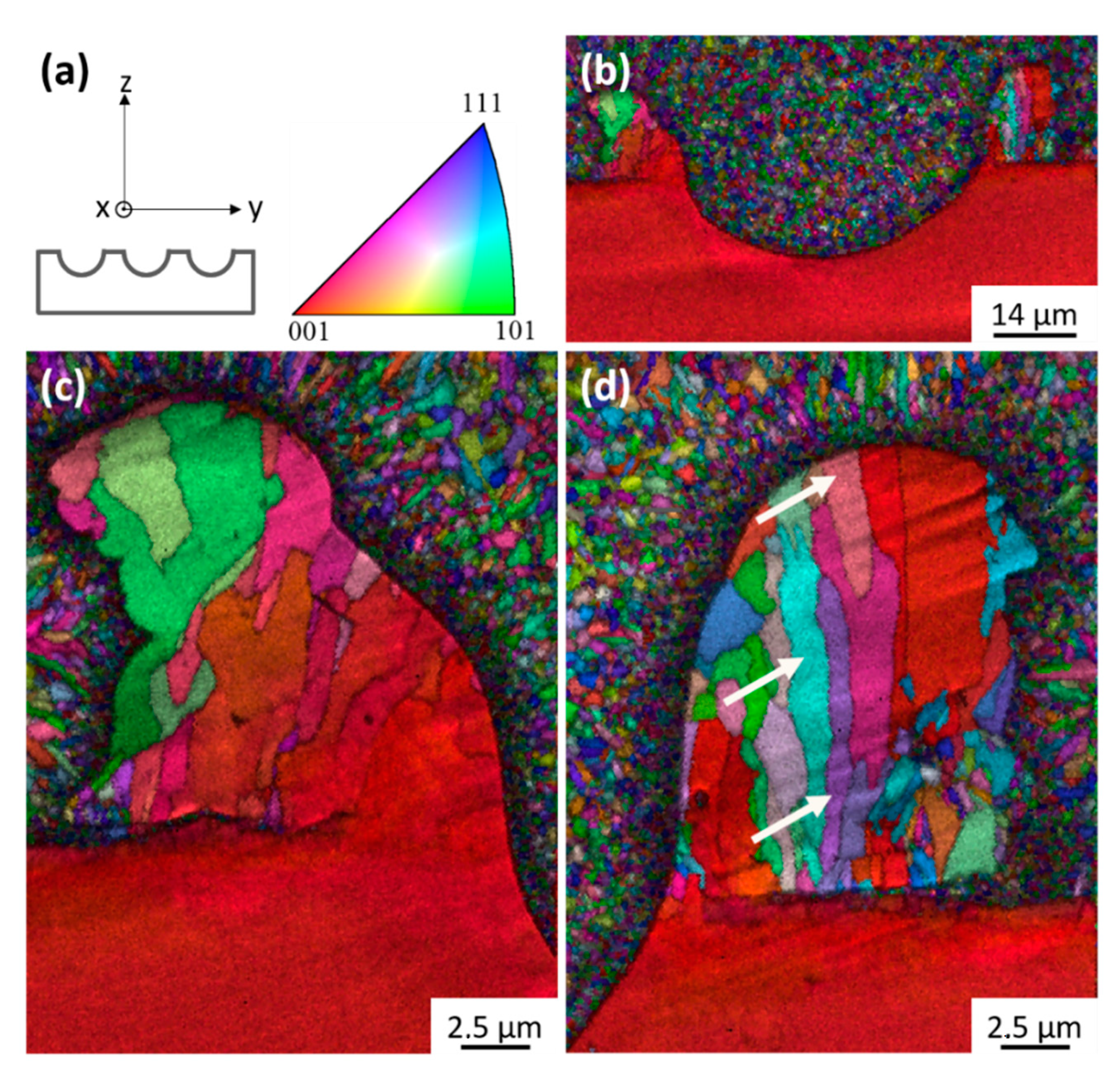
- The morphology of asperity/superalloy junction has an influence on the asperity cooling phenomena and, consequently, on the recrystallization mechanisms. Indeed, an important junction favors an epitaxial growth of the asperities with the substrate. On the contrary, a small junction promotes the formation of recrystallized asperities.
- Whatever the considered Ni-based single crystal superalloys, textured patterns including thermally affected volumes are quite similar. However, regarding thermal-affected volumes, slight dissimilarities were noticed between the same superalloys but having different microstructures.
- During infrared nanosecond laser ablation, Ni-based single crystal superalloys could be considered as “composite” with a γ phase more resistant to the ablation than γ′-precipitates. The local competition of melting and vaporization kinetics could explain the obtained thermal-affected volumes.
Author Contributions
Funding
Institutional Review Board Statement
Informed Consent Statement
Data Availability Statement
Acknowledgments
Conflicts of Interest
References
- Campbell, D.J. Advanced aero-engine concepts controls. In Advanced Aero-Engine Concepts and Controls; AGARD: Neuilly sur Seine, France, 1996. [Google Scholar]
- Delcourt, O. Les défits matériaux et procédés pour les équipements aéronautiques. In Proceeding of the Conférence A3TS, 2016. Available online: https://www.mediachimie.org/sites/default/files/Espace_p117.pdf (accessed on 29 October 2021).
- Reed, R.C. The Superalloys—Fundamentals and Applications; Cambridge University Press: Cambridge, UK, 2008. [Google Scholar]
- Paquin, S.; Cariou, R. Turbine Blade Having an Improved Structure. Patent WO 2018/189434A2, 18 October 2018. [Google Scholar]
- Rollinger, A.; Cariou, R.; Flamme, T.; Paquin, S. Turbine Blade Comprising a Cooling. Circuit. Patent WO 2018/060627 A1, 5 October 2017. [Google Scholar]
- Levi, C.G.; Hutchinson, J.W.; Vidal-Sétif, M.H.; Johnson, C.A. Environmental degradation of thermal-barrier coatings by molten deposits. MRS Bull. 2012, 37, 932–941. [Google Scholar] [CrossRef] [Green Version]
- Evans, A.G.; Mumm, D.R.; Hutchinson, J.W.; Meier, G.H.; Pettit, F.S. Mechanisms controlling the durability of Thermal Barrier Coatings. Progr. Mater. Sci. 2001, 46, 505–553. [Google Scholar] [CrossRef]
- Evans, H.E. Oxidation failure of TBC systems: An assessment of mechanisms. Surf. Coat. Technol. 2011, 206, 1512–1521. [Google Scholar] [CrossRef]
- Dryepondt, S.; Porter, J.R.; Clarke, D.R. On the initiation of cyclic oxidation-induced rumpling of platinum-modified nickel aluminide coatings. Acta Mater. 2009, 57, 1717–1723. [Google Scholar] [CrossRef]
- Giggins, C.S.; Kear, B.H.; Pettit, F.S.; Tien, J.K. Factors Affecting Adhesion of Oxide Scales on Alloys. Metall. Trans. 1974, 5, 1685–1688. [Google Scholar] [CrossRef]
- Evans, H.E. Modelling oxide spallation. Mater. High Temp. 1994, 12, 219–227. [Google Scholar] [CrossRef]
- Tolpygo, V.K.; Clarke, D.R. On the rumpling mechanism in nickel-aluminide coatings part II: Characterization of surface undulations and bond coat swelling. Acta Mater. 2004, 52, 5129–5141. [Google Scholar]
- Tolpygo, V.K.; Clarke, D.R. Surface rumpling of a (Ni, Pt)Al bond coat induced by cyclic oxidation. Acta Mater. 2000, 48, 3283–3293. [Google Scholar] [CrossRef]
- Tolpygo, V.K.; Clarke, D.R.; Murphy, K.S. Oxidation-induced failure of EB-PVD thermal barrier coatings. Surf. Coat. Technol. 2001, 146–147, 124–131. [Google Scholar] [CrossRef]
- Spitsberg, I.T.; Mumm, D.R.; Evans, A.G. On the failure mechanisms of thermal barrier coatings with diffusion aluminide bond coatings. Mater. Sci. Eng. A 2005, 394, 176–191. [Google Scholar] [CrossRef]
- Zhao, H.; Yu, Z.; Wadley, H.N.G. The influence of coating compliance on the delamination of thermal barrier coatings. Surf. Coat. Technol. 2010, 204, 2432–2441. [Google Scholar] [CrossRef]
- Kromer, R. Etude des Effets des Préparations de Surface Avant Projection Thermique—Application à un Système Barrière Thermique; Université de Technologie de Belfort-Montbéliard: Sevenans, France, 2016. [Google Scholar]
- Kromer, R.; Cormier, J.; Costil, S.; Courapied, D.; Berthe, L.; Peyre, P. High temperature durability of a bond-coatless plasma-sprayed thermal barrier coating system with laser textured Ni-based single crystal substrate. Surf. Coat. Technol. 2018, 337, 168–176. [Google Scholar] [CrossRef] [Green Version]
- Kromer, R.; Mauget, F.; Despres, L.; Costil, S.; Cormier, J. Thermo-mechanical fatigue evaluation of a thermal barrier coating bond-coatless system. Mater. Sci. Eng. A 2019, 756, 130–141. [Google Scholar] [CrossRef]
- Aufray, M. Fascicule: Adhésion et Adhérence des Matériaux. 2009. Available online: http://maelenn.aufray.free.fr/cours/fascicule-cours-adhesion-site-web.pdf (accessed on 29 October 2021).
- McBain, J.W.; Hopkins, D.G. On Adhesives and Adhesive Action. J. Phys. Chem. 1925, 29, 188–204. [Google Scholar] [CrossRef]
- Garcia-Alonso, D.; Serres, N.; Demian, C.; Costil, S.; Langlade, C.; Coddet, C. Pre-/during-/post-laser processes to enhance the adhesion and mechanical properties of thermal-sprayed coatings with a reduced environmental impact. J. Therm. Spray Technol. 2011, 20, 719–735. [Google Scholar] [CrossRef]
- Neves, D.; Diniz, A.E.; de Lima, M.S.F. Efficiency of the laser texturing on the adhesion of the coated twist drills. J. Mater. Process. Technol. 2006, 179, 139–145. [Google Scholar] [CrossRef]
- Kromer, R.; Costil, S.; Cormier, J.; Courapied, D.; Berthe, L.; Peyre, P.; Boustie, M. Laser surface patterning to enhance adhesion of plasma sprayed coatings. Surf. Coat. Technol. 2015, 278, 171–182. [Google Scholar] [CrossRef]
- Courapied, D.; Kromer, R.; Berthe, L.; Peyre, P.; Costil, S.; Cormier, J.; Boustie, M.; Milhet, X. Laser adhesion test for thermal sprayed coatings on textured surface by laser. J. Laser Appl. 2016, 28, 022509. [Google Scholar] [CrossRef]
- Kromer, R.; Costil, S.; Cormier, J.; Berthe, L.; Peyre, P.; Courapied, D. Laser Patterning Pretreatment before Thermal Spraying: A Technique to Adapt and Control the Surface Topography to Thermomechanical Loading and Materials. J. Therm. Spray Technol. 2016, 25, 401–410. [Google Scholar] [CrossRef] [Green Version]
- Kromer, R.; Danlos, Y.; Aubignat, E.; Verdy, C.; Costil, S. Coating deposition and adhesion enhancements by laser surface texturing—metallic particles on different classes of substrates in cold spraying process. Mater. Manuf. Process. 2017, 32, 1642–1652. [Google Scholar] [CrossRef]
- Pollock, T.M.; Tin, S. Nickel-based surperalloys for advanced turbine engines: Chemistry, microstructure, and properties. J. Propuls. Power 2006, 22, 361–374. [Google Scholar] [CrossRef]
- Wahl, J.B.; Harris, K. Improved 3rd Generation Single Crystal Superalloy CMSX-4® Plus (SLS)—A Study of Evolutionary Alloy Development; Cannon-Muskegon: Muskegon, MI, USA, 1984. [Google Scholar]
- Tin, S.; Pollock, T.M. Phase instabilities and carbon additions in single-crystal nickel-base superalloys. Mater. Sci. Eng. A 2003, 348, 111–121. [Google Scholar] [CrossRef]
- Rame, J.; Utada, S.; Bortoluci Ormastroni, L.; Mataveli Suave, L.; Menou, E.; Despres, L.; Kontis, P.; Cormier, J. Platinum containing new generation nickel-based superalloy for single crystalline applications. In Superalloys 2020 TMS; Springer: Cham, Switzerland, 2020; pp. 71–81. [Google Scholar]
- Semaltianos, N.G.; Perris, W.; Cheng, J.; French, P.; Sharp, M.; Dearden, G.; Watkins, K.G. Picosecond laser ablation of nickel-based superalloy C263. Appl. Phys. A 2010, 98, 345–355. [Google Scholar] [CrossRef]
- Semaltianos, N.G.; Perris, W.; French, P.; Sharp, M.; Dearden, G.; Logothetidis, S.; Watkins, K.G. Femtosecond laser ablation characteristics of nickel-based superalloy C263. Appl. Phys. A 2009, 94, 999–1009. [Google Scholar] [CrossRef]
- McDonald, J.P.; Ma, S.; Pollock, T.M.; Yalisove, S.M.; Nees, J.A. Femtosecond pulsed laser ablation dynamics and ablation morphology of nickel based superalloy CMSX-4. J. Appl. Phys. 2008, 103, 1–8. [Google Scholar] [CrossRef]
- Petronic, S.; Drecun-Nesic, S.; Milosavljevic, A.; Sedmak, A.; Popovic, M.; Kovacevic, A. Microstructure changes of nickel-base superalloys induced by Interaction with femtosecond laser beam. Acta Phys. Pol. A 2009, 116, 550–552. [Google Scholar] [CrossRef]
- Ma, S.; McDonald, J.P.; Tryon, B.; Yalisove, S.M.; Pollock, T.M. Femtosecond laser ablation regimes in a single-crystal superalloy. Metall. Mater. Trans. A 2007, 38, 2349–2357. [Google Scholar] [CrossRef]
- Chichkov, B.N.; Momma, C.; Nolte, S.; Alvensleben, F.v.; Tünnermann, A. Femtosecond, picosecond and nanosecond laser ablation of solids. Appl. Phys. A 1996, 63, 109–115. [Google Scholar] [CrossRef]
- Zeng, X.; Mao, X.; Greif, R.; Russo, R.E. Experimental investigation of ablation efficiency and plasma expansion during femtosecond and nanosecond laser ablation of silicon. Appl. Phys. A 2005, 80, 237–241. [Google Scholar] [CrossRef]
- Costil, S.; Despres, L.; Cormier, J.; Mauget, F.; Cariou, R.; Joulia, A.; Saboundji, A.; Mataveli Suave, L. Laser surface texturing to imporve EB-PVD thermal barrier coating adhesion. In Proceedings of the ITSC, Quebec, QC, Canada, 24–28 May 2021. [Google Scholar]
- Grosdidier, T.; Hazotte, A.; Simon, A. Precipitation and dissolution processes in γ/γ′ single crystal nickel-based superalloys. Mater. Sci. Eng. A 1998, 256, 183–196. [Google Scholar] [CrossRef]
- Costil, S.; Lamraoui, A.; Langlade, C.; Heintz, O.; Oltra, R. Surface modifications induced by pulsed-laser texturing—Influence of laser impact on the surface properties. Appl. Surf. Sci. 2014, 288, 542–549. [Google Scholar] [CrossRef]
- Kato, T.; Kobayashi, T.; Nikov, R.G.; Nedyalkov, N.N.; Atanasov, P.A. Surface modification of Ti6Al4V by nanosecond laser ablation for biomedical applications. J. Phys. Conf. Ser. 2015, 605, 012022. [Google Scholar]
- Kurella, A.; Dahotre, N.B. Review paper: Surface Modification for Bioimplants: The Role of Laser Surface. J. Biomater. Appl. 2005, 20, 1–25. [Google Scholar] [CrossRef] [PubMed]
- Jouvard, J.M.; Soveja, A.; Pierron, N.; Fonderie, D.; Creusot, L. Thermal modelling of metal surface texturing by pulsed laser. In Proceedings of the COMSOL Users Conference, Paris, France, 7 November 2006. [Google Scholar]
- Semak, V.V.; Hopkins, J.A.; Mccay, M.H.; Mccay, T.D. A concept for a hydrodynamic model of keyhole formation and support during laser welding. ICALEO 1994, 641–650. [Google Scholar]
- Semak, V.; Matsunawa, A.A. The role of recoil pressure in energy balance during laser materials processing. J. Phys. D Appl. Phys. 1997, 30, 2541–2552. [Google Scholar] [CrossRef]
- Soveja, A.; Jouvard, J.M.; Grevey, D. Metal Surface Laser Texturing: Multiphysics Modelling of a Single Impact Effect. In Proceedings of the COMSOL Users Conference, Grenoble, France, 23–24 October 2007. [Google Scholar]
- Leitz, K.; Redlingshöfer, B.; Reg, Y.; Otto, A.; Schmidt, M. Metal Ablation with Short and Ultrashort Laser Pulses. Physics Proc. 2011, 12, 230–238. [Google Scholar] [CrossRef] [Green Version]
- Bäuerle, D. Laser Processing and Chemistry, 4th ed.; Springer: Berlin/Heidelberg, Germany, 2011. [Google Scholar]
- Allmen, M.v.; Blatter, A. Laser-Beam Interactions with Materials, 2nd ed.; Springer: Berlin/Heidelberg, Germany, 1998. [Google Scholar]
- Acharya, M.V.; Fuchs, G.E. The effect of long-term thermal exposures on the microstructure and properties of CMSX-10 single crystal Ni-base superalloys. Mater. Sci. Eng. A 2004, 381, 143–153. [Google Scholar] [CrossRef]
- Wu, J.; Jiang, X.; Wang, Y.; Dong, J.; Lou, L. Effects of Ta on microstructure stability and mechanical properties of hot corrosion resistant Ni-based single crystal superalloys during long-term thermal exposure. Mater. Sci. Eng. A 2021, 806, 140829. [Google Scholar] [CrossRef]
- Steuer, S.; Hervier, Z.; Thabart, S.; Castaing, C.; Pollock, T.M.; Cormier, J. Creep behavior under isothermal and non-isothermal conditions of AM3 single crystal superalloy for different solutioning cooling rates. Mater. Sci. Eng. A 2014, 601, 145–152. [Google Scholar] [CrossRef]
- Selezneff, S. Etude et Développement de Revêtements Gamma-Gamma’ Riches en Platine, Elaborés par Spark Plasma Sintering (SPS); Application au Système Barrière Thermique; Université de Toulouse: Toulouse, France, 2011. [Google Scholar]
- Giamei, A.F.; Anton, D.L. Rhenium additions to a Ni-base superalloy: Effects on microstructure. Metall. Mater. Trans. A 1985, 16, 1997–2005. [Google Scholar] [CrossRef]
- Caron, P.; Khan, T. Evolution of Ni-based superalloys for single crystal gas turbine blade applications. Aerosp. Sci. Technol. 1999, 3, 513–523. [Google Scholar] [CrossRef]
- Durrand-Charre, M. The Microstructure of Superalloys; CRC Press: Boca Raton, FL, USA, 2000. [Google Scholar]
- Caron, P.; Khan, T. Improvement of creep strength in a nickel-base single-crystal superalloy by heat treatment. Mater. Sci. Eng. 1983, 61, 173–184. [Google Scholar] [CrossRef]


| Alloy | Solvus | Density (g/cm3) | Composition (wt.%) | ||||||||
|---|---|---|---|---|---|---|---|---|---|---|---|
| Ni | Co | Cr | Mo | W | Ta | Al | Ti | Re | |||
| AM1 | 1268 +/− 5 | 8.59 | Bal. | 6.5 | 7.8 | 2.0 | 5.7 | 7.9 | 5.2 | 1.1 | / |
| CMSX-4 | 1293 +/− 7 | 8.7 | Bal. | 9.7 | 6.4 | 0.6 | 6.4 | 6.5 | 5.6 | 1.1 | 2.9 |
| CMSX-4 Plus | 1334 +/− 5 | 8.93 | Bal. | 10.0 | 3.5 | 0.6 | 6.0 | 8.0 | 5.7 | 0.9 | 4.8 |
| MAR M200 + Hf | 1205 −/+ 10 | 8.61 | Bal. | 9.5 | 8.6 | - | 11.8 | - | 4.9 | 1.9 | - |
| MC2 | 1265 +/− 5 | 8.63 | Bal. | 5.0 | 8.0 | 2.0 | 8.0 | 6.0 | 5.0 | 1.5 | - |
| Alloy | Solution Heat Treatment | Aging Treatment |
|---|---|---|
| AM1 | 1300 °C/3 h/AQ | 1100 °C/5 h/AQ + 870 °C/16 h/AQ |
| CMSX-4 | 1277 °C/2 h + 1288 °C/2 h + 1296 °C/3 h + 1304 °C/3 h + 1313 °C/2 h + 1316 °C/2 h + 1318 °C/2 h + 1321 °C/2 h/GFC | 1140 °C/6 h/AQ + 871 °C/20 h/AQ |
| CMSX-4 Plus | 1313 °C/2 h + 1318 °C/2 h + 1324 °C/6 h + 1335 °C/6 h/GFC | 1163 °C/6 h/AQ + 871 °C/20 h/AQ |
| MAR M200 + Hf | 1210 °C/0.5 h + 1225 °C/0.5 h + 1240 °C/4 h/AQ | 1100 °C/5 h/AQ + 870 °C/16 h/AQ |
| MC2 | 1300 °C/3 h/AQ | 1080 °C/6 h/AQ + 870 °C/16 h/AQ |
| Alloy | Density (g/cm3) | Composition (wt.%) | |||||||||
|---|---|---|---|---|---|---|---|---|---|---|---|
| Ni | Co | Cr | Mo | Al | Ti | Nb | C | B | Fe | ||
| Inconel 718 | 8.19 | 50–55 | <1 | 17–21 | 2.8–3.3 | 0.2–0.8 | 0.65–1.15 | 4.75–5.5 | 0.04 | 0.02 | 18.5 |
| Heading | MAR M200 + Hf | MAR M200 + Hf + AgT | AM1 | AM1 + AgT | CMSX4 Plus | CMSX4 Plus + AgT |
|---|---|---|---|---|---|---|
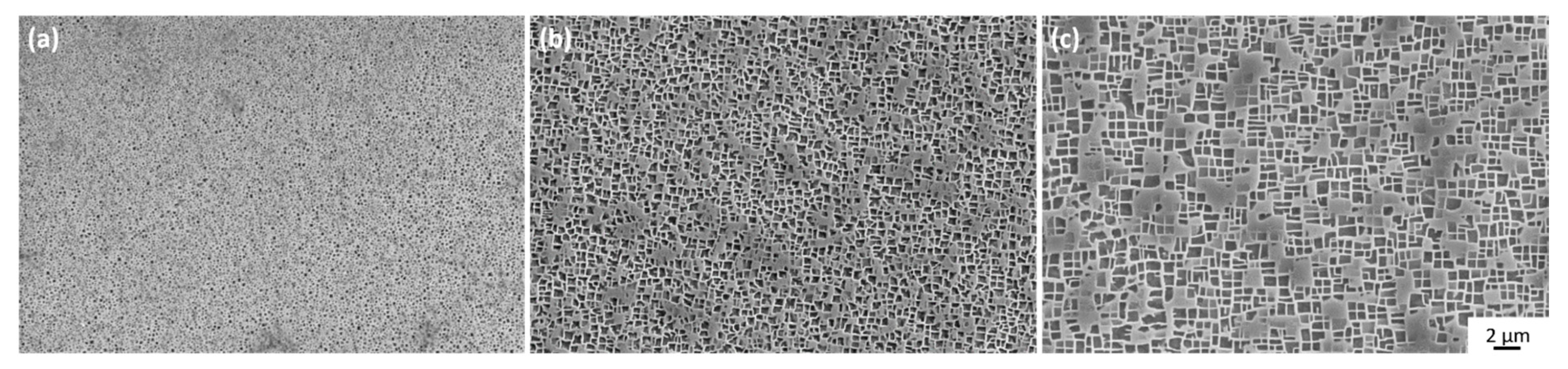
| Dendrite | <100 nm | ~300 nm | ~295 nm | ~375 nm | ~610 nm | ~635 nm |
| Interdendritic area | <100 nm | ~345 nm | ~315 nm | ~380 nm | ~625 nm | ~650 nm |
Publisher’s Note: MDPI stays neutral with regard to jurisdictional claims in published maps and institutional affiliations. |
© 2021 by the authors. Licensee MDPI, Basel, Switzerland. This article is an open access article distributed under the terms and conditions of the Creative Commons Attribution (CC BY) license (https://creativecommons.org/licenses/by/4.0/).
Share and Cite
Despres, L.; Costil, S.; Cormier, J.; Villechaise, P.; Cariou, R. Impact of Laser Texturing on Ni-Based Single Crystal Superalloys. Metals 2021, 11, 1737. https://doi.org/10.3390/met11111737
Despres L, Costil S, Cormier J, Villechaise P, Cariou R. Impact of Laser Texturing on Ni-Based Single Crystal Superalloys. Metals. 2021; 11(11):1737. https://doi.org/10.3390/met11111737
Chicago/Turabian StyleDespres, Lucille, Sophie Costil, Jonathan Cormier, Patrick Villechaise, and Romain Cariou. 2021. "Impact of Laser Texturing on Ni-Based Single Crystal Superalloys" Metals 11, no. 11: 1737. https://doi.org/10.3390/met11111737
APA StyleDespres, L., Costil, S., Cormier, J., Villechaise, P., & Cariou, R. (2021). Impact of Laser Texturing on Ni-Based Single Crystal Superalloys. Metals, 11(11), 1737. https://doi.org/10.3390/met11111737