Article

Towards Qualification in the Aviation Industry: Impact Toughness of Ti6Al4V(ELI) Specimens Produced through Laser Powder Bed Fusion Followed by Two-Stage Heat Treatment

by
Lehlohonolo Francis Monaheng
1,*,
Willie Bouwer du Preez
2 and
Claudia Polese
3,4
1
Department of Mechanical and Mechatronics Engineering, Faculty of Engineering, Built Environment and Information Technology, Central University of Technology Free State, Bloemfontein 9300, South Africa
2
Center for Rapid Prototyping and Manufacturing, Faculty of Engineering, Built Environment and Information Technology, Central University of Technology Free State, Bloemfontein 9300, South Africa
3
School of Mechanical, Industrial and Aeronautical Engineering, University of the Witwatersrand, Johannesburg 2050, South Africa
4
DSI-NRF Centre of Excellence in Strong Material, University of the Witwatersrand, Johannesburg 2050, South Africa
*
Author to whom correspondence should be addressed.
Metals 2021, 11(11), 1736; https://doi.org/10.3390/met11111736
Submission received: 1 October 2021 / Revised: 22 October 2021 / Accepted: 24 October 2021 / Published: 30 October 2021
(This article belongs to the Special Issue Lightweight Alloys for Aerospace Applications)

Abstract

:
Laser powder bed fusion (L-PBF) has the potential to be applied in the production of titanium aircraft components with good mechanical properties, provided the technology has been qualified and accepted in the aviation industry. To achieve acceptance of the L-PBF technology in the aircraft industry, mechanical property data needed for the qualification process must be generated according to accepted testing standards. The impact toughness of Ti6Al4V extra low interstitial (ELI) specimens, produced through L-PBF followed by annealing, was investigated in this study. Charpy impact testing complying with American Standard Test Method (ASTM) E23 was performed with specimens annealed and conditioned at low temperature. On average, the toughness recorded for the specimens with 3D-printed and machined V-notches was 28 J and 31 J, respectively. These results are higher than the 24 J required in the aerospace industry. Finally, fractographic analyses of the fracture surfaces of the specimens were performed to determine the fracture mechanism of the Ti6Al4V(ELI) impact specimens.

1. Introduction

The requirement of the aerospace industry for materials with exceptional strength to weight ratio and outstanding mechanical properties has justified the growing use of additively manufactured (AM) Ti6Al4V extra low interstitial (ELI), even for mission-critical components, such as a landing gear nose wheel fork [1,2]. Ti6Al4V(ELI) is a corrosion-resistant ( α + β ) alloy that contains aluminum and vanadium elements as α and β stabilisers, respectively. Due to the α to β transformation, the microstructure and mechanical properties, such as tensile strength and ductility, of this alloy can be tailored through heat treatment [3]. For example, the tensile elongation and impact toughness of the Ti6Al4V(ELI) alloy can be enhanced through high-temperature annealing for extended dwell periods at the expense of tensile strength and hardness [4]. The as-built AM Ti6Al4V(ELI) components have ultimate tensile strength (UTS) of 1155 MPa with a low elongation of about 4.1%, which can be altered to 1230 MPa, 914 MPa, and 871 MPa after stress relief, recrystallisation annealing, and two-stage heat treatment, respectively [5]. These are done to optimize elongation to approximately 11.5% after two-stage heat treatment. Whereas, mill-annealed wrought Ti6Al4V(ELI) has the UTS of 930–970 MPa with an elongation of 17–19% [6].
Due to the significant cost of the Ti6Al4V(ELI) raw material, a near-net-shape manufacturing technology, such as metal additive manufacturing, has become attractive for the aviation industry [7]. This layer-by-layer technique of creating three-dimensional (3D) objects from digital computer model data minimizes material wastage by selectively melting and fusing predetermined layers of metal powder and un-melted powder can be reused [8]. Standard classification of the technology includes powder bed fusion (PBF), which is more specifically termed selective laser melting (SLM) when applied to metal powders [9]. Direct metal laser sintering (DMLS) is an SLM terminology used by the machine supplier EOS GmbH [10]. This technology has various advantages over conventional manufacturing methods. These include reduction of the production cost of the aircraft components, high design freedom which includes topology optimization, and rapid prototyping [11].
Stringent standards in the aircraft industry limit the application of Ti6Al4V components produced through the L-PBF technology [12]. Aircraft components must be approved by the aviation authorities such as the Federal Aviation Administration (FAA) and the European Aviation Safety Agency (EASA). Every technology used for aircraft part production must be licensed and certified for such a purpose [13]. The recent proposal done by Duncan et al. states that the qualification and certification of L-PBF for application in aerospace should not differ from the conventional manufacturing process [14]. The mechanical properties of a material produced through a particular technology must be established based on accepted standard test methods performed under the correct operational environment [15]. To achieve acceptance of the L-PBF technology for producing Ti6Al4V(ELI) components for the aircraft industry, the impact toughness of the produced component is one of the properties that must be determined.
Impact toughness is a measure of the amount of energy absorbed by the material during the rapid application of load before fracture. It is usually determined through the Charpy impact test with specimens prepared to have a specific dimension, geometry, and temperature. The test is performed based on American Standard Test Method (ASTM) E23 [16]. For materials with high strength, such as titanium alloys, the impact energy is relatively insensitive to the temperature and has low toughness [17].
The conventionally processed Ti6Al4V alloy has a microstructure and mechanical properties that vary with the thermal processing history. For example, the as-cast Ti6Al4V(ELI) contains colonies of lamellar alpha with a typical impact toughness of 11 J and can be altered through various heat treatments [18]. The α lamellar and equiaxed microstructure of the rolled Ti6Al4V(ELI) plate can absorb an impact energy of 19 J and 13 J, respectively [19]. On the other hand, Ti6Al4V(ELI) components produced by the powder compact extrusion process have a typical Widmanstätten/lamellar microstructure. This microstructure is formed as the result of diffusion-controlled growth of the α phase as the material is air-cooled from the β phase after exiting from the extrusion die. Annealing of such components results in impact toughness of 19.3 J and this value is comparable with a typical value for the wrought Ti6Al4V(ELI) [20].
Ti6Al4V(ELI) parts produced using the L-PBF technique consist of different mechanical properties as compared to traditionally manufactured components. They consist of large prior beta grains with fine needle-like microstructure resulting from the rapid cooling accompanied by the localized heating inherent in L-PBF. This is commonly known as martensite structure (acicular α ’ martensite in a columnar prior- β grain) [21]. The as-built impact energy of L-PBF Ti6Al4V(ELI) specimens at a temperature −50 °C is 14.41 J [22]. This toughness value of as-built Ti6Al4V(ELI) specimens is 45% lower than the 24 J needed in the aviation industry [23].
The challenges of the Ti6Al4V(ELI) parts built through L-PBF method have been highlighted by previous studies. The size of the pore, and other geometric features of the porous structures are controlled by the processing parameters [24]. Muiruri et al. reported a pore size of 0.06 to 1.36 μm for power setting, laser diameter, hatch spacing, and layer thickness of 175 W, 80, 100 and 30 μ m, respectively. Such pore size was reported to have no critical effect on the initiation of the failure, although playing a role in the eventual failure. The initiation of failure in the Charpy specimens resulted from the stress concentration effect at the root of the V-notch [25]. Another shortcoming of L-PBF is the relative high surface roughness which results from the partially melted or unmelted powder particles from the surrounding powder bed, sticking to the surface of the part and the staircase effect [26]. An adverse residual stress state is caused by the thermal gradient resulting from the short interaction time between laser and powder, which is accompanied by high localized heating and subsequent rapid cooling. To mitigate the negative effect of the internal residual stress such as deformation of the built part, support structures are commonly used to anchor the part on the built substrate and assist in the dissipation of heat [27].
An appropriate post-process heat treatment improves the Ti6Al4V(ELI) toughness by reducing the negative effect of the residual stress inherent in L-PBF. For example, L-PBF Ti6Al4V(ELI) specimens which were stress-relieved at a temperature of 650 °C and a soaking period of 3 h in an argon environment recorded an improvement of 20% in the impact energy as compared to the as-built specimens [4]. Furthermore, an improvement of 26% in the impact toughness value was also reported for V-notch specimens after stress-relieving heat treatment when compared to the toughness required by the American Society of Metals (ASM) [23]. In contrast, Yasa et al. annealed Ti6Al4V specimens at a temperature of 735 °C for 2 h in an argon environment and recorded a slight decrease of the impact toughness as compared to the as-built samples tested at room temperature [28]. However, there is limited knowledge on the effect of two-stage heat treatment on the impact energy of Ti6Al4V(ELI) specimens produced using L-PBF process.
In this study, the effect of two-stage heat treatment on the impact toughness of Ti6Al4V(ELI) specimens produced by L-PBF technology and conditioned to achieve a low test temperature, was investigated. The fracture surfaces of the impact specimens were also evaluated. Conclusions on the possibility of using the L-PBF technology to produce structural aircraft parts are presented.

2. Materials and Methods

The methodology carried out was aimed at investigating the effect of two-stage heat treatment, build orientation, and the type of V-notch creation on the impact toughness of the Ti6Al4V (ELI) specimens. Triplicate specimens were built in each of the three orthogonal orientations, stress relieved, heat-treated at high temperature, and tested for impact toughness. For comparison with the as-built state, data was collected from the literature. Finally, the characteristics of the fracture surfaces of the specimens were evaluated using scanning electron microscopy (SEM).

2.1. Specimen Preparation

An EOSINT M280 DMLS machine (EOS GmbH, Munich, Germany), equipped with a 200 W Ytterbium fiber laser with a laser beam diameter of 80 μ m   and powder layer thickness of 30 μ m , was used to build Charpy impact specimens from Ti6Al4V(ELI) powder. Spherical Ti6Al4V(ELI) powder supplied by (TLS Technik GmbH & Co. Spezialpulver KG, Bitterfeld-Wolfen, Germany) with an average powder particle size of less than 45 μ m was used to build the test specimens. The powder composition that complied with ASTM F3001-14 and used in this study are shown in Table 1.
A total of 18 Charpy impact specimens were divided into two sets. The first set of 9 samples were 3D printed with a V-notch and for the second set of 9 specimens, the V-notch was machined using a wire cutter. Each set consisted of three specimens built along each of the three orthogonal directions (XY, YX, and Z) as shown in Figure 1a, and had square cross-sectional dimensions of 10 mm × 10 mm × 55 mm as illustrated in Figure 1b and required by the ASTM E23. After the L-PBF process, all specimens were submitted to a two-stage heat treatment.

2.2. Two-Stage Heat Treatment

Firstly, to relieve the residual stress, the specimens, still secured on the base plate, were heated to a temperature of 650 °C at a rate of 3.6 °C/min in a vacuum furnace, soaked at 650 °C for 3 h, and furnace cooled to room temperature. Thereafter, the specimens were cut off from the building substrate by a wire electrical discharge machine. Subsequently, the samples were submitted to a high-temperature anneal (HTA) heat treatment. This consisted of heating at a rate of 5.2 °C/min to 950 °C in a vacuum furnace, followed by soaking at this temperature for 3 h, before the furnace cooled to room temperature.

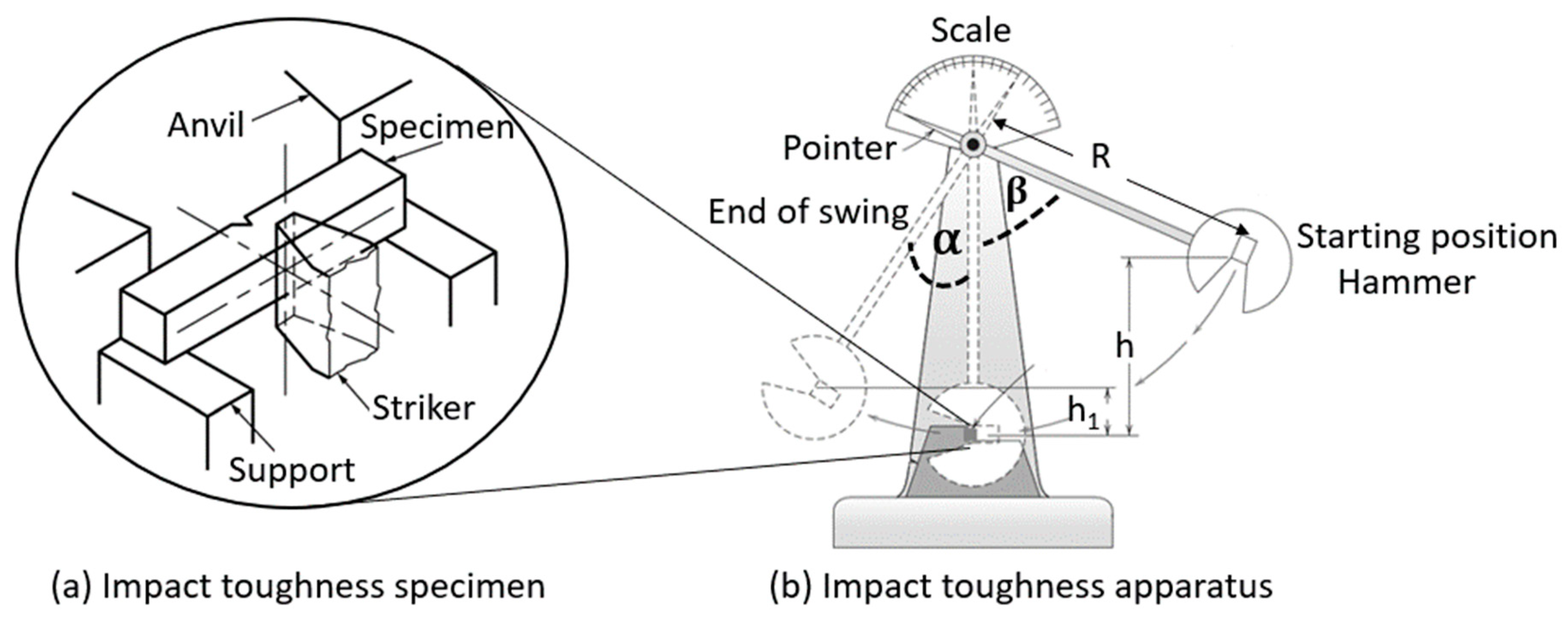
2.3. Testing Procedure

The Charpy impact test was performed in compliance with the ASTM E23-18 standard [16]. An Instron 450MP2-J1 impact test machine, with a maximum frame capacity of 300 J, was used to measure the impact resistance of the specimens. Initially, all specimens were cooled to a low temperature by immersing them into an ethanol solution and conditioning them to a temperature of −50 °C with liquid nitrogen. The schematic illustration of the Charpy impact testing apparatus and the specimen is shown in Figure 2. The specimen was placed on the supports and against the anvil as shown in Figure 2a to receive a single blow of a moving mass (hammer) shown in Figure 2b. The hammer had sufficient energy to break the specimen with a single impact load and its link (pendulum) had a pointer to indicate the start and the end of the swing position. The pendulum hammer had falling and rising angles of β and α , respectively.
The absorbed energy is computed as the difference between the potential energy at the starting position (h = R R c o s β ) and that at the end of the swing position (h1 =   R R cos α ). The initial and final potential energy of the pendulum is given by Equations (1) and (2), where R is the pendulum radius.
  E i = m g R ( 1 cos β )
E f = m g R ( 1 cos α )  
The energy absorbed (ab) by the specimen is provided by Equation (3):
E a b = m g h ( cos β cos α )  
This impact energy caused all specimens to fracture at the V-notch since it was the point of the stress concentration.

2.4. Fractography

The microstructure of the specimens was studied using a ZEISS optical microscope. Three representative samples were mounted on MultiFast phenolic resin to allow microstructure analysis on the XY, ZX, and ZY planes concerning the coordinate system shown in Figure 1. Samples were metallographically prepared by firstly grinding them using 46   μ m waterproof SiC discs, followed by mechanical polishing on the Struers Tegramin-25 machine, using DiaMaxx Poly 9 and 3 μ m diamond suspensions. Finally, the samples were etched using Kroll’s reagent.
Fractographic analysis was performed on the fracture surfaces of the impact specimens using a Jeol (JSM-6610) scanning electron microscope (SEM, Jeol, Peabody, MA, USA). The increased depth of field allowed the evaluation of the effects of the 3D-printed and wire-cut V-notches on the fracture surfaces of the tested specimens. The impact of the build orientation on the fracture surface was also investigated. The percentage shear fracture of the specimens with 3D-printed and wire-cut V-notches was also determined based on the ASTM E23-18 standard [16].

3. Results and Discussions

3.1. Impact Toughness

It is clear from Table 2 that the impact toughness of specimens with wire-cut V-notches is higher than that of 3D-printed V-notches for all orientations. The XY 3D-printed V-notch specimens absorbed 20% less impact energy as compared to the similar wire-cut V-notch specimens. For both the YX and Z 3D-printed V-notch specimens, the toughness was 3.5% lower as compared to the similar wire-cut V-notch specimens.
The dispersion of the impact toughness dataset, relative to the mean values determined through standard deviation analysis, is illustrated in Figure 3. Specimens with 3D-printed V-notch were compared with wire-cut V-notch. Dispersion of the XY specimen with a 3D-printed notch falls outside that of the wire-cut notch, suggesting a significant difference in the impact toughness. As for specimens built along YX and Z, comparable results were obtained.
The lowest recorded value of impact energy in this study, for both 3D-printed and wire-cut V-notch Ti6Al4V(ELI) specimens, is 26 J, which is 8% more than the impact energy required in the aviation industry [23]. When comparing these results with the impact energy values of as-built L-PBF Ti6Al4V(ELI) specimens available in the literature, more than 45% improvement was achieved [22], and for the stress-relieved and heat-treated specimens, more than 40% improvement was recorded [25] (see the data given in Table 3).

3.2. Fractography Results

The Ti6Al4V(ELI) Charpy specimens produced through L-PBF and submitted to two-stage heat treatment depict four distinct fracture modes when subjected to the impact load. This corresponds to other high-strength metals including 12CrMoV steel [31,32]. In Figure 4 the fracture zones of the Charpy specimens with wire-cut and 3D-printed V-notches are shown for various orientations. I in image (a) represents the crack initiation zone, II is for the zone of crack growth (unstable fracture), III is for shear lips, and IV is for precritical growth (final fracture). Images (a), (b), and (c) are for wire-cut V-notches and (d), (e) as well as (f) are for Charpy specimen with 3D-printed notches.
A zone of mesoscopic scale is formed in the tip of the notch after impact due to the development of the localized plastic deformation (zone I), followed by the propagation of macro defects, which result from the formation of a plastic hinge (zone II ). Thereafter, the shear lips were formed as shown in Figure 4 (zone III) as the material deforms due to shear stress. Finally, a region of rotational-shear deformation was formed as a result of a high-speed development of fracture that leads to final fracture (zone IV).
Microstructures of Ti6Al4V(ELI) produced through L-PBF can be altered through heat treatment and are directly related to mechanical properties. A previous study by Lütjering showed that a reduced tensile strength and an increased ductility result from coarsened α phase and large colony size [33]. A very fine acicular (needle-like) microstructure was reported for the as-built Ti6Al4V(ELI) specimens, which resulted from the inherited rapid cooling of the material during L-PBF [34]. Such specimens have a UTS of 1267 MPa and impact energy shown in Table 3. Microstructure of the two-stage heat-treated Ti6Al4V(ELI) specimens built through L-PBF are shown in Figure 5 in various planes XY, ZY, and ZX concerning the coordinate system shown in Figure 1. The microstructure obtained after two-stage heat treatment (650 for 3 h and followed by 950 for the same dwelling period with subsequent furnace cooling) and consists of acicular α and a small amount of β . Whereas various planes of the specimens have similar microstructure. The starting of the α globalisation was also observed as indicated with arrows. These microstructures are comparable to two-stage hear treated (950 ℃, air cooled, followed by 700 ℃ and furnace cooled) Ti6Al4V(ELI) specimens reported by Becker et al., which have a tensile strength of 871 MPa and a percentage elongation of 11.5 [5].
Secondary electrons (SE) SEM images of a Charpy impact toughness specimen shown in Figure 6a reveal four distinct fracture modes. In Figure 6b–e, detailed features of each fracture mode are illustrated.
The crack initiation zone in Figure 6a of the Z specimen with 3D-printed V-notch contained secondary crack, while the unstable zone had multiple micro-cracks as illustrated in Figure 6d. Dimples were observed in the shear-lip region shown in Figure 6c and flat facets surrounded by dimples with clear tear directionality were observed in the final fracture shown in Figure 6e.
In all specimens, fracture initiated from the root of the notch due to stress concentration and secondary cracks were depicted, as shown in Figure 6b and Figure 7 (XY1, YX1, and Z1). This secondary crack nucleation ability of the annealed Ti6Al4V(ELI) impact toughness samples near the notch arose from the ductility of the material. The impact energy was dissipated by the creation and movement of dislocations in the crystal lattices of the structure near the crack tip [35]. As a result, the specimens absorbed the high impact energy and a fibrous fracture surface was depicted in the crack initiation region.
As a crack propagated through an unstable fracture region, a fracture surface with dimples, micro-cracks, and pores was depicted, as can be seen in Figure 6d and Figure 7 (XY2, YX2, and Z2). At the sides of the specimens, material ruptured due to shear stress set up by the applied load at about 45 o with respect to the normal stress, resulting in a fibrous surface that is associated with plastic deformation, and formed a shear lip. This phenomenon occurs when the shear stress exceeds the shear strength of the material as stated by the ASTM E23-18 standard [16]. The shear areas, as a percentage of the total fracture surface of 3D-printed and the wire-cut V-notch specimens, were 40% and 30%, respectively. However, both types of specimens had tortuous fracture surfaces with dimples in the shear lip region. The final fracture occurred microseconds later with evidence of flat facet fracture surrounded by dimples, pointing towards a mixed fracture mode (ductile and brittle fracture).
As seen in Table 2, the surface roughness in the root of the 3D-printed V-notch significantly reduced the impact toughness as compared to the impact toughness value of the wire-cut V-notch. This variation in the impact toughness value is attributed to a conspicuous variation between 3D-printed and wire-cut V-notch specimens, as observed by comparing Figure 6b with Figure 7 (Z1). The 3D-printed V-notch contained un-melted powder particles in the notch region resulting in an uneven surface that acted as a stress raiser, whereas the wire-cut V-notch had a smooth surface.

4. Conclusions

The impact toughness of Ti6Al4V(ELI) specimens produced through L-PBF followed by two-stage heat treatment (stress-relieved at 650 °C and HTA at 950 °C, each for 3 h), was investigated in this study. Charpy impact testing complying with ASTM E23 was performed with specimens annealed and conditioned at a low temperature of −50 °C. The following conclusions were deduced:
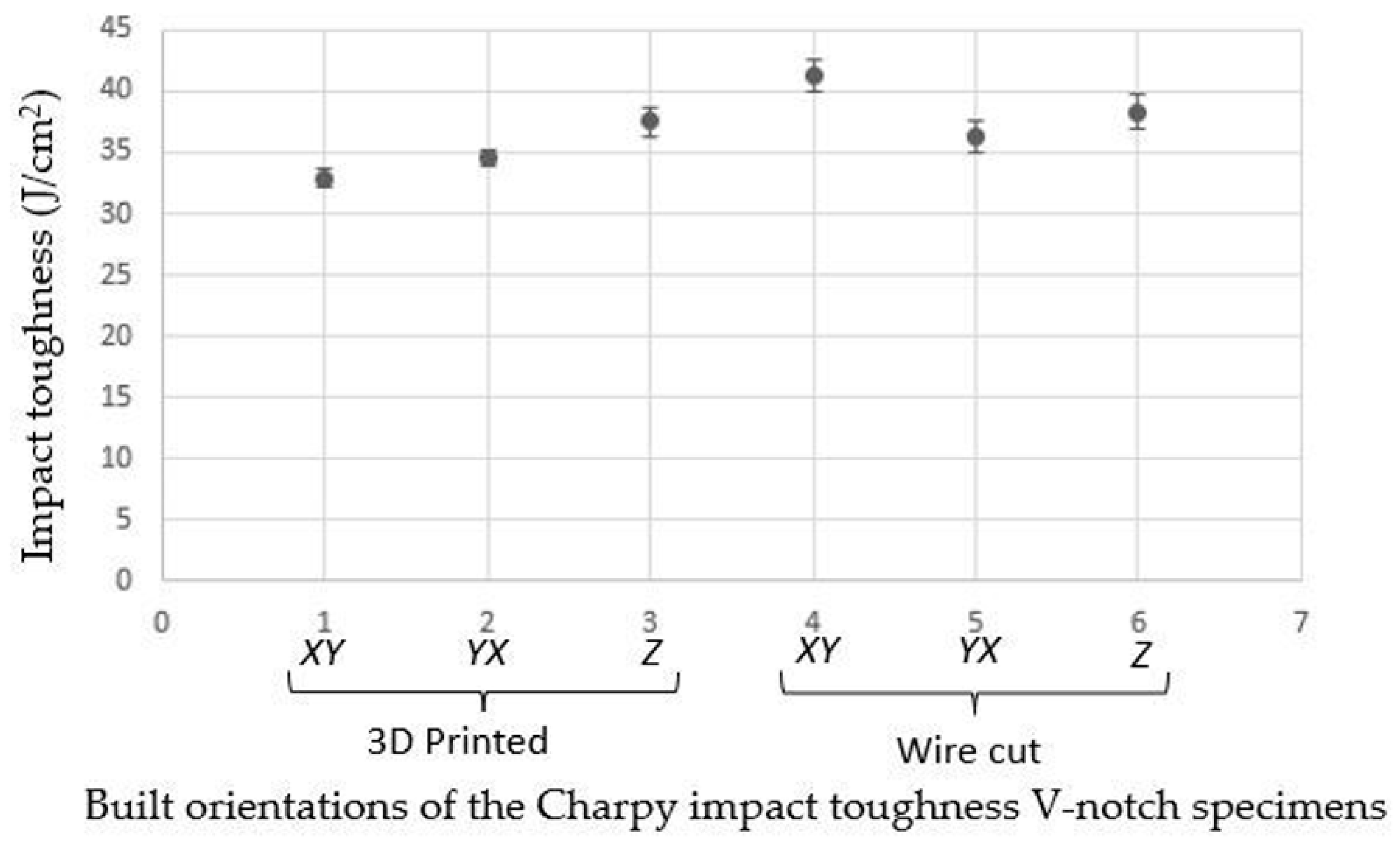
  • Specimens with wire-cut V-notches have a higher value of impact toughness as compared to that of 3D-printed V-notches for all build orientations. Therefore, wire-cut V-notches resist impact energy better than the 3D-printed notches.
  • The impact toughness determined for specimens with 3D-printed V-notches along the XY built orientation significantly differs from that measured for the wire-cut V-notch specimens.
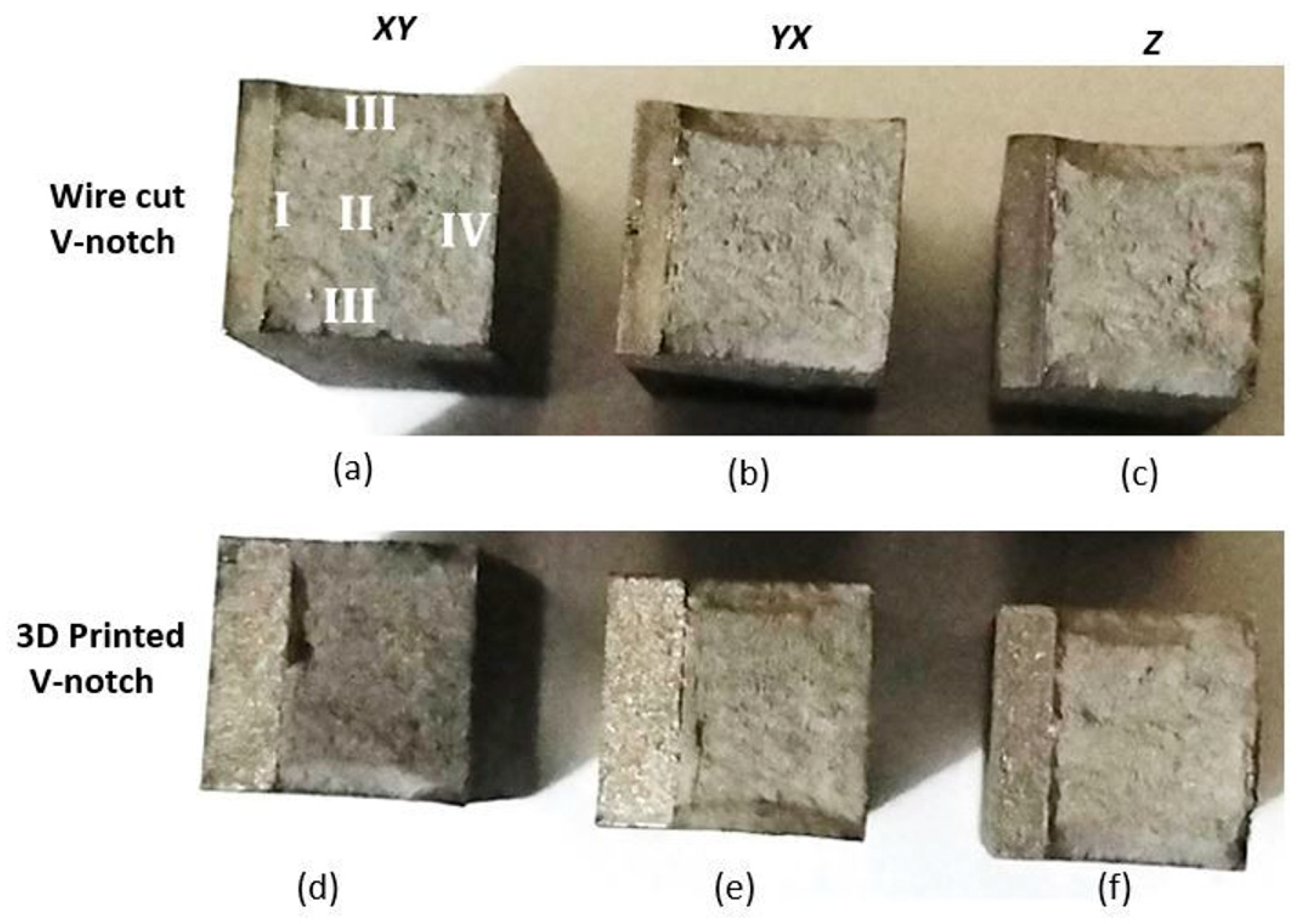
  • The percentage shear fracture area of the specimens with 3D-printed V-notches was larger than that of specimens with wire-cut V-notches.
  • The presence of the 3D-printed V-notch can reduce the impact toughness by 3.5–20% as compared to the wire-cut V-notch.
  • All build orientations of the specimens revealed acceptable impact energy after two-stage heat treatment when compared to the toughness required in the aircraft industry.
  • Two-stage heat treatment improved the impact toughness of the Ti6Al4V(ELI) specimens built through L-PBF by approximately 40%. Such improvement is 8% more than the requirement of the aerospace industry.
  • The microstructure obtained after two-stage heat treatment consists of acicular α and a small amount of β.
  • The surface roughness in the root of the 3D-printed V-notches of the Ti6Al4V(ELI) specimens significantly reduced the impact toughness as compared to the impact toughness value of the wire-cut V-notches.
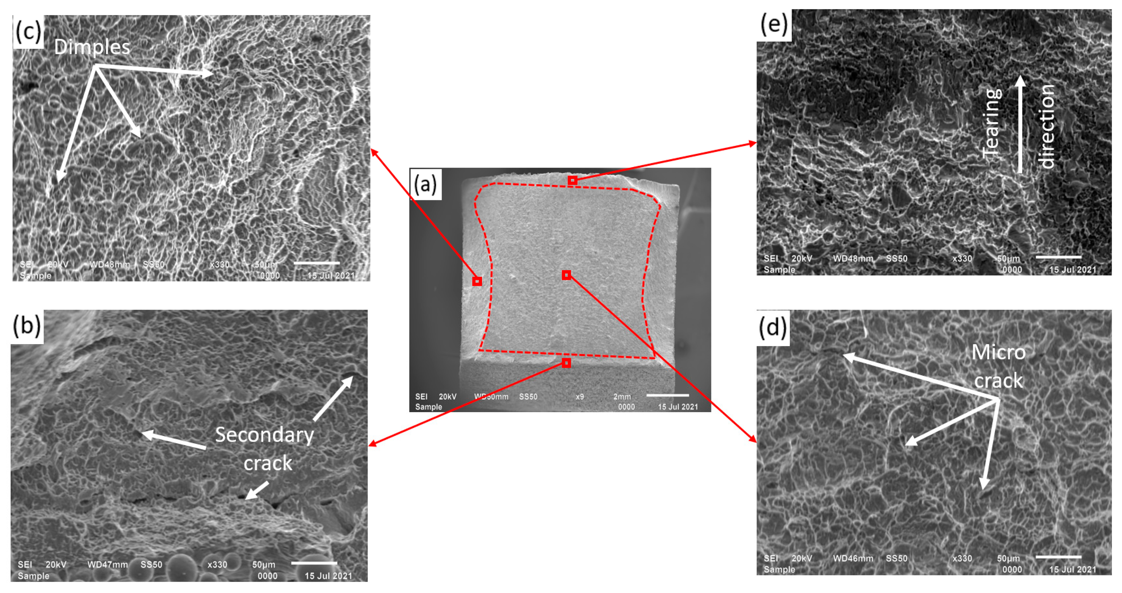
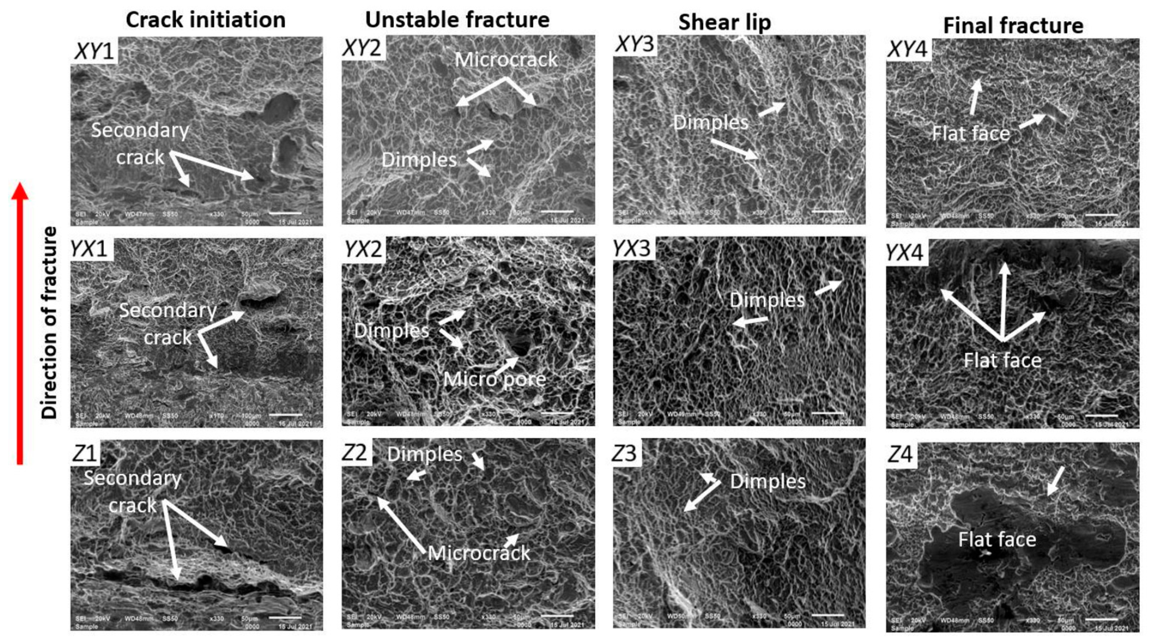
  • The Ti6Al4V(ELI) specimens consist of a ductile fracture mechanism, since it consists of tortuous fracture surfaces with dimples in the shear lip region, when subjected to impact load.
  • The final fracture region of the Ti6Al4V(ELI) specimens subjected to impact load has a flat face fracture surrounded by dimples, pointing towards a mixed fracture mode (ductile and brittle fracture).
  • Parts that were built using L-PBF have impact toughness acceptable for the production of aircraft structural parts which operate at a low temperature of −50 °C.
  • The current study provides the data for future work on the qualitative relationship between fracture toughness and impact toughness of Ti6Al4V(ELI) produced through L-PBF and annealing. Future quantitative fractographic analyses of the ductile dimple’s morphology, e.g., shape and size, could also provide additional information on the impact behavior of this alloy.

Author Contributions

Conceptualization, L.F.M., W.B.d.P. and C.P.; methodology, L.F.M.; formal analysis, L.F.M.; writing—original draft preparation, L.F.M.; writing—review and editing, L.F.M., W.B.d.P. and C.P.; supervision, W.B.d.P. and C.P.; funding acquisition, W.B.d.P. All authors have read and agreed to the published version of the manuscript.

Funding

This research was supported and funded by the South African Department of Science and Innovation through the Collaborative Program in Additive Manufacturing, contract No.: CSIR-NLC-CPAM-18-MOA-CUT-01.

Institutional Review Board Statement

Not applicable.

Informed Consent Statement

Not applicable.

Data Availability Statement

Not applicable.

Acknowledgments

The authors express their gratitude to the Center for Rapid Prototyping and Manufacturing (CRPM) of the Faculty of Engineering, Built Environment and Information Technology, Central University of Technology, Free State, for producing and heat treating the specimens. The SecMet of the subsidiary of MegChem Holding (Pty) Ltd. is also acknowledged for the impact testing of the specimens. The authors acknowledge the Department of Geology of the University of the Free State for providing the SEM machine for analysis of the fracture surface of the specimens.

Conflicts of Interest

The authors declare no conflict of interest.

References

  1. Conner, B.P.; Manogharam, G.P.; Martof, A.N.; Rodomsky, L.M.; Rodomsky, C.M.; Jordan, D.C.; Limperos, J.W. Making sense of 3-D printing: Creating a map of additive manufacturing products and services. Addit. Manuf. 2014, 1, 64–76. [Google Scholar] [CrossRef]
  2. Monaheng, L.F.; Preez, W.B.; Kotze, N.; Vermeulen, M. Topology optimisation of an aircraft nose-wheel fork for production in Ti6Al4V by the Aeroswift high-speed laser powder bed fusion machine. In Proceedings of the 14th World Conference on Titanium, MATEC Web of conferences, Nantes, France, 12 October 2020. [Google Scholar]
  3. Moletsane, M.G.; Krakhmalev, P.; Kazantseva, N.; du Plessis, A.; Yadroitsava, I.; Yadroitsev, I. Tensile properties and microstructure of direct metal laser-sintered Ti6Al4V (ELI) alloy. South. African J. Ind. Eng. 2016, 27, 110–121. [Google Scholar] [CrossRef] [Green Version]
  4. Lee, K.A.; Kim, Y.K.; Yu, J.H.; Park, S.H.; Kim, M.C. Effect of heat treatment on microstructure and impact toughness of Ti-6Al- 4V manufactured by selective laser melting process. Arch. Metall. Mater. 2017, 62, 1341–1346. [Google Scholar] [CrossRef] [Green Version]
  5. Becker, T.H.; Beck, M.; and Scheffer, C. Microstructure and mechanical properties of direct metal laser sintered TI-6AL-4V. South. African J. Ind. Eng 2015, 26, 6. [Google Scholar] [CrossRef] [Green Version]
  6. Donachie, M.J. Titanium: A Technical Guide, 2nd ed.; ASM International: Geauga County, OH, USA, 2000. [Google Scholar]
  7. Singh, P.; Pungotra, H.; Kalsi, N. On the characteristics of titanium alloys for the aircraft applications. Mater. Proc. 2017, 4, 8971–8982. [Google Scholar] [CrossRef]
  8. Kruth, J.P.; Levy, G.; Klocke, F.; Childs, T.H.C. Consolidation phenomena in laser and powder-bed based layered manufacturing. CIRP Ann. Manuf. Technol. 2007, 56, 730–759. [Google Scholar] [CrossRef]
  9. ASTM F2792-12a. Standard Terminology for Additive Manufacturing Technologies. Available online: http://www.ciri.org.nz/nzrma/technologies.html (accessed on 2 July 2021).
  10. EOS, DMLS Technology for Metal 3D Printer. Available online: https://www.eos.info/en/industrial-3d-printing/additive-manufacturing-how-it-works/dmls-metal-3d-printing (accessed on 15 October 2021).
  11. Khorasan, I.M.; Ghasemi, A.H.; Rolfe, B.; Gibson, I. Additive manufacturing a powerful tool for the aerospace industry. Rapid Prototyp. J. 2021. [Google Scholar] [CrossRef]
  12. Singamneni, S.; LV, Y.; Hewitt, A.; Chalk, R.; Thomas, W.; Jordison, D. Additive Manufacturing for the Aircraft Industry: A Review. J. Aeronaut. Aerosp. Eng. 2019, 8, 215. [Google Scholar] [CrossRef] [Green Version]
  13. Portolés, L.; Jordá, O.; Jordá, L.; Uriondo, A.; Esperon-Miguez, M.; Perinpanayagam, S. A qualification procedure to manufacture and repair aerospace parts with electron beam melting. J. Manuf. Syst. 2016, 41, 65–75. [Google Scholar] [CrossRef]
  14. Gibbons, D.W.; Serfontein, J.P.L.; van der Merwe, A.F. Mapping the path to certification of metal laser powder bed fusion for aerospace applications. Rapid Prototyp. J. 2021, 27, 355–361. [Google Scholar] [CrossRef]
  15. Federal Aviation Administration: Part 23-Airworthiness Standards: Normal, Utility, Acrobatic, and Commuter Category Airplane. Available online: https://www.govinfo.gov/content/pkg/CFR-2011-title14-vol1/pdf/CFR-2011-title14-vol1-part23.pdf (accessed on 15 October 2010).
  16. ASTM E23-18. Standard Test Methods for Notched Bar Impact Testing of Metallic Materials. Available online: https://www.astm.org/Standards/E23 (accessed on 28 October 2020).
  17. Callister, D.; William, J. Failure. In Materials Science and Engineering: An Introduction, 7th ed.; Hyton, J., Ed.; John Wiley & Sons, Inc.: New York, NY, USA, 2007; pp. 206–251. [Google Scholar]
  18. Reda, R.; Nofal, A.; Hussein, A.H. Effect of single and duplex stage heat treatment on the microstructure and mechanical properties of cast Ti-6Al-4V alloy. Met. Microstruct. Anal. 2013, 2, 388–393. [Google Scholar] [CrossRef] [Green Version]
  19. Buirette, C.; Huez, J.; Gey, N.; Vassel, A.; Andrieu, E. Study of crack propagation mechanisms during Charpy impact toughness tests on both equiaxed and lamellar microstructures of Ti6Al4V titanium alloy. Mater. Sci. Eng. A 2014, 618, 546–557. [Google Scholar] [CrossRef] [Green Version]
  20. Singh, A.P.; Yang, F.; Torrens, R.; Gabbitas, B. Heat treatment, impact properties, and fracture behaviour of Ti6Al4V Alloy produced by powder compact extrusion. Materials 2019, 12, 3824. [Google Scholar] [CrossRef] [PubMed] [Green Version]
  21. Sallica-Leva, E.; Jardini, A.L.; Fogagnolo, J.B. Microstructure and mechanical behavior of porous Ti6Al4V parts obtained by selective laser melting. J. Mech. Behav. Biomed. Mater. 2013, 26, 98–108. [Google Scholar] [CrossRef] [PubMed]
  22. Muiruri, A.; Maringa, M.; du Preez, W.B.; Masu, L. Variation of impact toughness of as-built DMLS Ti6Al4V (ELI) specimens with temperature. S. Afr. J. Ind. Eng. 2018, 29, 284–298. [Google Scholar]
  23. ASM Aerospace Specification Metals Inc. Titanium Ti6Al4V (Grade 5), ELI, Annealed. Available online: http://asm.matweb.com/search/SpecificMaterial.asp?bassnum=MTP643 (accessed on 29 June 2021).
  24. Ding, L.; Tan, S.; Chen, W.; Jin, Y.; Zhang, Y. Manufacturability analysis of extremely fine porous structures for selective laser melting process of Ti6Al4V alloy. Rapid Prototyp. J. 2021, 27, 1523–1537. [Google Scholar] [CrossRef]
  25. Muiruri, A.; Maringa, M.; du Preez, W.B.; Masu, L. Effects of stress-relieving heat treatment on impact toughness of direct metal laser sintering (DMLS)-produced Ti6Al4V (ELI) parts. JOM 2019, 72, 1175–1185. [Google Scholar] [CrossRef]
  26. Duan, W.; Han, J.; Xia, Q.; Wang, K.; Wu, M.; Song, D. Investigation on the relationship between bending angle of the overhanging surface and overhanging surface quality printed using selective laser melting. Rapid Prototyp. J. 2021, 27, 1573–1579. [Google Scholar] [CrossRef]
  27. Li, L.; Pan, T.; Zhang, Y.C.; Cui, W.; Yan, L.; Liou, F. Deformations and stresses prediction of cantilever structures fabricated by selective laser melting process. Rapid Prototyp. J. 2021, 27, 453–464. [Google Scholar] [CrossRef]
  28. Yasa, E.; Deckers, J.; Kruth, J.P.; Rombouts, M.; Luyten, J. Charpy impact testing of metallic selective laser melting parts. Virtual Phys. Prototype. 2010, 5, 89–98. [Google Scholar] [CrossRef]
  29. Thejane, K.; Chikosha, S.; du Preez, W.B. Characterisation and monitoring of Ti6Al4V (ELI) powder used in different selective laser melting systems. S. Afr. J. Ind. Eng. 2017, 28, 161–171. [Google Scholar] [CrossRef] [Green Version]
  30. ASTM F3001-14. Standard Specification for Addtivive Manufacturing Titanium 6 Aluminum 4 Vanadium ELI (Extra Low Interstitial) with Powder Bed Fusion. Available online: https://www.astm.org/Standards/F3001.htm (accessed on 28 October 2020).
  31. Panin, S.V.; Maruschak, P.O.; Vlasov, I.V.; Ovechkin, B.B. Impact toughness of 12Cr1MoV steel. Part 1—Influence of temperature on energy and deformation parameters of fracture. Theor. Appl. Fract. Mech. 2016, 83, 105–113. [Google Scholar] [CrossRef]
  32. Panin, S.V.; Maruschak, P.O.; Vlasov, I.V.; Sergeev, V.P.; Ovechkin, B.B.; Neifeld, V.V. Impact toughness of 12Cr1MoV steel. Part 2—Influence of high intensity ion beam irradiation on energy and deformation parameters and mechanisms of fracture. Theor. Appl. Fract. Mech. 2016, 83, 82–92. [Google Scholar] [CrossRef]
  33. Lütjering, G. Influence of processing on microstructure and mechanical properties of (α + β) titanium alloys. Mater. Sci. Eng. A. 1998, 243, 32–45. [Google Scholar] [CrossRef]
  34. Vrancken, B.; Thijs, L.; Kruth, J.P.; Van Humbeeck, J. Heat treatment of Ti6Al4V produced by selective laser melting: Microstructure and mechanical properties. J. Alloys Compd. 2012, 541, 177–185. [Google Scholar] [CrossRef] [Green Version]
  35. Kysar, J.W. Energy dissipation mechanisms in ductile fracture. J. Mech. Physic Solid 2003, 51, 795–824. [Google Scholar] [CrossRef]
Figure 1. (a) An illustration of the V-notched Charpy impact toughness test specimen’s build orientation and (b) geometry with dimensions in mm as required by the ASTM E23. Unit: mm.
Metals 11 01736 g001
Figure 2. (a) Schematic description of Charpy impact toughness test specimen positioning; (b) drawing of impact testing apparatus.
Metals 11 01736 g002
Figure 3. An illustration of the impact toughness dispersion concerning the built orientations of the 3D print and wire-cut V-notch specimens.
Metals 11 01736 g003
Figure 4. An illustration of the fracture zones of the Ti6Al4V(ELI) Charpy impact toughness specimens for the various orientation of the wire-cut and 3D-printed V-notches. I ,   II   ,   III ,   and   IV in image (a) represents the crack initiation, crack growth, shear lips, and final fracture, respectively. Images (ac) are for wire-cut V-notches and (d,e) as well as (f) are for Charpy specimen with 3D-printed notches.
Metals 11 01736 g004
Figure 5. Optical microscope images for XY, ZY, and ZX orientations of Ti6Al4V specimens produced by the L-PBF process and followed by two-stage heat treatment. The arrows indicate globalized α grains (light) where β is indicated by dark marks.
Metals 11 01736 g005
Figure 6. (a) SEM SE images of the fracture surface of a Z specimen with 3D-printed V-notch, (b) crack initiation zone, (c) shear-lip region (d) unstable fracture, and (e) final fracture.
Metals 11 01736 g006
Figure 7. Fracture surfaces of the various regions of fracture for the Charpy impact toughness specimens built with different orientations (XY, YX, and Z).
Metals 11 01736 g007
Table 1. Chemical composition of TLS Technik Ti6Al4V(ELI) powder.
MaterialsTitanium (Ti)Aluminum (Al)Vanadium
(V)
Iron
(Fe), max
Oxygen
(O), max
Nitrogen
(N), max
TLS powder [29]90.30%5.56%4.02%0.23%0.12%0.04%
ASTM F3001-14 [30]Balance5.5–6.5%3.5–4.5%0.25%0.13%0.05%
Table 2. Charpy impact toughness in Joule per square centimeter for the 3D-printed and wire-cut V-notch Ti6Al4V(ELI) specimens built in three orthogonal directions.
NotchBuild
Orientations
Charpy Impact Toughness (J/cm²)
ValuesMinMaxMeanStandard
Deviation
3D PrintedXY3334333334330.7
YX3535343435350.7
Z3638393639381.3
Wire cutXY4041434043411.3
YX3536383538361.3
Z3838403840381.4
Table 3. Impact toughness values of Ti6Al4V(ELI) specimens built by the L-PBF technique.
Materials and ReferencesL-PBF Machine TypeTesting EnvironmentSpecimen
Conditions
Impact Energy (J)
Ti6Al4V(ELI) [22]EOSINT M280−50 °CAs-built 13.3
Ti6Al4V(ELI) [25]Stress relieved at 650 °C for 3 h14.9
Ti6Al4V [28]SLM Ambient As-built11.5
Annealed at 730 °C for 2 h10.1
Ti6Al4V [4]SLMAmbient As-built6.0
Stress relieved at 650 °C for 3 h7.3
Publisher’s Note: MDPI stays neutral with regard to jurisdictional claims in published maps and institutional affiliations.

