Article

Ultra Low-Cycle Fatigue Behavior Comparison between Additively Manufactured and Rolled 17-4 PH (AISI 630) Stainless Steels

Department of Civil Engineering, University of Arkansas, Fayetteville, AR 72701, USA
*
Author to whom correspondence should be addressed.
Metals 2021, 11(11), 1726; https://doi.org/10.3390/met11111726
Submission received: 23 August 2021 / Revised: 25 October 2021 / Accepted: 25 October 2021 / Published: 28 October 2021
(This article belongs to the Special Issue Fatigue Behavior of Structural Steel)

Abstract

:
This study investigates the mechanical behavior of additively manufactured (AM) 17-4 PH (AISI 630) stainless steels and compares their behavior to traditionally produced wrought counterparts. The goal of this study is to understand the key parameters influencing AM 17-4 PH steel fatigue life under ULCF conditions and to develop simple predictive models for fatigue-life estimation in AM 17-4 steel components. In this study, both AM and traditionally produced (wrought) material samples are fatigue tested under fully reversed (R = −1) strain controlled (2–4% strain) loading and characterized using micro-hardness, x-ray diffraction, and fractography methods. Results indicate decreased fatigue life for AM specimens as compared to wrought 17-4 PH specimens due to fabrication porosity and un-melted particle defect regions which provide a mechanism for internal fracture initiation. Heat treatment processes performed in this work, to both the AM and wrought specimens, had no observable effect on ULCF behavior. Result comparisons with an existing fatigue prediction model (the Coffin–Manson universal slopes equation) demonstrated consistent over-prediction of fatigue life at applied strain amplitudes greater than 3%, likely due to inherent AM fabrication defects. An alternative empirical ULCF capacity equation is proposed herein to aid future fatigue estimations in AM 17-4 PH stainless steel components.

1. Introduction

Current approaches to the seismic resistant design of steel structures rely on ductile energy dissipation mechanisms that are only optimized at a crude level due to the economics and limitations of traditional fabrication technologies (e.g., eccentrically braced frame links, reduced beam-section moment connections, etc.). Researchers often seek better control and optimization within these ductile mechanisms to improve global seismic performance and create economic savings throughout the structural system. Additive manufacturing (AM) through selective laser melting (SLM) of metal powders is a novel fabrication solution for seismic structural fuse components having optimized geometries too complex for traditional fabrication methods, including casting.
One potential drawback of AM SLM is the creation of material voids during fabrication, caused by un-melted particles and gas entrapment, which can negatively affect mechanical performance [1,2,3,4,5,6,7,8]. Figure 1 shows an illustration of the SLM fabrication procedure, where metal powders are deposited and then melted in layers to form three-dimensional parts. While some research on the mechanical behavior of AM metal parts under monotonic loading, high-cycle fatigue (HCF) and low-cycle fatigue (LCF) have been conducted [2,9,10,11,12,13], little is understood about the mechanical performance under ultra low-cycle fatigue (ULCF) conditions (Nf < 100 cycles) such as those produced during design-level seismic events. Ultra low-cycle fatigue (ULCF) driven fractures are a common performance limitation of existing seismic systems and improved understanding of ULCF behavior in AM metal materials may help future developments in seismic fuse geometry optimization.
Because AM SLM components are created by melting sequential particle layers, material build orientation can lead to anisotropic behavior and the formation of internal voids. Research by Yadollahi et al. [14] identified voids resembling both a slit and a sphere within AM SLM metals resulting from un-melted particles and gas entrapment, respectively. Internal material void formations oriented perpendicular to the intended loading direction have been shown to exhibit lower mechanical performance than void formations oriented parallel to the loading direction [1,2,10]. Additionally, sequential powder melting can form elongated grains in the build direction, deflecting crack propagation when loaded parallel to the build orientation, prolonging the time to failure [11,15].
Heat treatment has been shown to affect the strength and HCF performance of AM SLM metal parts. Several studies have successfully used solution annealing and peak-age heat treatment (Condition A and H900) to achieve comparable yield and ultimate strengths in AM 17-4 PH steels compared to wrought counterparts [9,11,14]. These improvements are due to the fine chromium–nickel–copper precipitation in the AM steel, which prevent dislocation movement and increase hardness, yield, and ultimate strength [9,11,14]; however, heat treated samples often have higher amounts of martensite, a stronger and more brittle material phase than austenite, which can result in a low elongation-to-failure [9,11], possibly affecting ULCF performance under large inelastic strains. Because retained austenite in non-heat-treated samples can improve material fracture toughness due to strain-martensite phase transformation [16,17], it is unclear how heat treatment will affect the ULCF behavior of 17-4 PH stainless steels. In [14], Yadollahi et al. investigated the HCF behavior of heat treated (solution annealing and peak aging) and non-heat treated AM 17-4 PH samples, and found the non-heat treated samples outperformed the heat-treated samples. While multiple studies have investigated the fatigue strength of AM parts in HCF and LCF regimes, investigations into ULCF behavior of 17-4 PH steels are lacking.
Understanding the mechanical performance of AM 17-4 PH steel components in ULCF is needed for the development of optimized energy dissipative components subjected to large repeated strains (such as yielding dampers and structural fuse elements in buildings during seismic loading) [18]. ULCF fracture processes are fundamentally different than those in the HCF regime as they form through a process of micro-void growth and coalescence during material yielding [19,20,21,22,23]. Komotori et al. [21] studied the effect of low ductility metal (cast iron) grain size under ULCF, where internal fractures were driven by micro-void coalescence via detachment of the matrix from the interstitial carbon inclusions. Additionally, the strain magnitude and ratio of the ULCF loading can alter internal void shape formation, leading to flattened void shapes and increased stress concentrations at void boundaries, resulting in shortened fatigue life [19,22].
This work aims to improve the understanding of AM 17-4 PH stainless steels during ULCF loading and develop predictive tools for estimating ULCF life in structural components subject to inelastic strains. Ductile fracture behavior from tensile testing will provide a performance baseline, with strain controlled (2–4% strain amplitude) fatigue testing used to characterize cyclic performance parameters. Micro-hardness, X-ray diffraction (XRD), and scanning electron microscopy (SEM) are used to study phase composition and fracture surface features. The following section describes the detailed experimental procedure, including sample fabrication and testing approach. Next, results from the mechanical characterizations are described, and ULCF prediction approaches for AM 17-4 PH steels are proposed. Following that, conclusions regarding AM 17-4 PH stainless steel behavior in ULCF are presented.

2. Sample Fabrication, Mechanical Testing, and Material Characterization Procedures

A total of nine AM samples were fabricated by the National Institute of Standards and Technology (NIST) and a private industry partner using an EOSINT M270 direct metal laser-sintering system using EOS standard fabrication parameters which deposit material in 20 μm thick layers in a checkerboard pattern (providing rotation between layers). Current high costs associated with AM metal fabrication prohibited the testing of multiple replicate specimens. The chemical composition of the metal powder used to fabricate the specimens is shown in Table 1. Half of the samples were subjected to a heat treatment (650 °C for 1 h), as recommended by EOS, while the other half were left in the “as-built” condition. To limit surface roughness effects resulting from AM fabrication, and to provide a consistent surface condition with the wrought materials, all AM specimens were machined to ASTM sample specifications as shown in Figure 2 after being heat treated. Wrought samples were machined from a hot-rolled 17-4 PH steel plate. A set of wrought samples were tested as-received (W-AR), while another set of wrought samples were heat treated at 650 °C for 4 h and cooled overnight in the furnace.
Displacement controlled tensile ductile fracture and ULCF tests were performed in accordance with ASTM E606/E606M-12 [24] using a Servohydraulic Biaxial Fatigue Testing Machine (manufactured by Walter + Bai AG, Lohningen, Switzerland). The experimental set-up is shown in Figure 3. In all ULCF testing, specimens were subjected to strain-controlled fully reversed (R = −1) uni-axial cyclic strains at constant strain-amplitudes (Δε/2) of 0.02, 0.03 and 0.04, respectively. All AM specimens were fabricated in the horizontal build orientation and loaded perpendicular to the layer build direction as shown in Figure 4.
To help identify the ULCF mechanisms leading to fracture, each sample was investigated using SEM, micro-hardness testing and XRD. All SEM images were taken using a Tescan Vega 3 SEM. Vicker’s micro-hardness surface testing was performed using a Pace Technologies (model HV-1000Z) micro-hardness tester, applying a load of 0.098 N (100-gf) over a dwell time of 15 s. Multiple micro-hardness measurements were taken from a quadrant of the gage and grip area of each sample (see Figure 2). X-ray diffraction (XRD) measurements from the grip cross-section of each fatigue specimen were taken using a PANalytical X’Pert MRD diffractometer with Cu Kα1 radiation (λ = 1.540598 Å) at an operating voltage and current of 45 kV and 40 mA, respectively. Additionally, metallographic investigations of the specimen surfaces were conducted following polishing and etching with Fry’s reagent to reveal the microstructure.

3. Results and Discussion

3.1. Effect of Heat Treatment Processes on Tensile Behavior

Because post-yield material behavior can control ULCF crack initiation (i.e., void initiation, growth, and coalescence), understanding post-yield mechanical behavior in the heat-treated and non-heat-treated AM specimens may provide insight into material ULCF performance. Results from monotonic tensile testing indicate that heat treatment following the AM SLM fabrication process results in reduced ductility and early initiation of yield. Table 2 shows the tensile mechanical properties for the AM and wrought specimens, showing a nearly 19% reduction in yield stress and 19% decrease in fracture strain between the AM as-built (AM-AB) and AM heat-treated (AM-HT) specimens. Post-yield tensile behavior indicates that the heat treatment increases the ultimate tensile strength (UTS) leading to a larger strain-hardening ratio for the AM materials. From Table 2, the UTS of the AM-HT specimens increased by nearly 31% compared to the AM-AB specimens. This post-yield strain-hardening behavior differs from observations in the wrought materials, where heat treatment in the wrought (W-HT) samples results in a UTS reduction. It should be noted that the lower yield strength of the AM specimens will result in a slight increase in plastic strain demand; however, this plastic strain demand increase will be very small and will diminish within the first few loading cycles due to strain hardening.

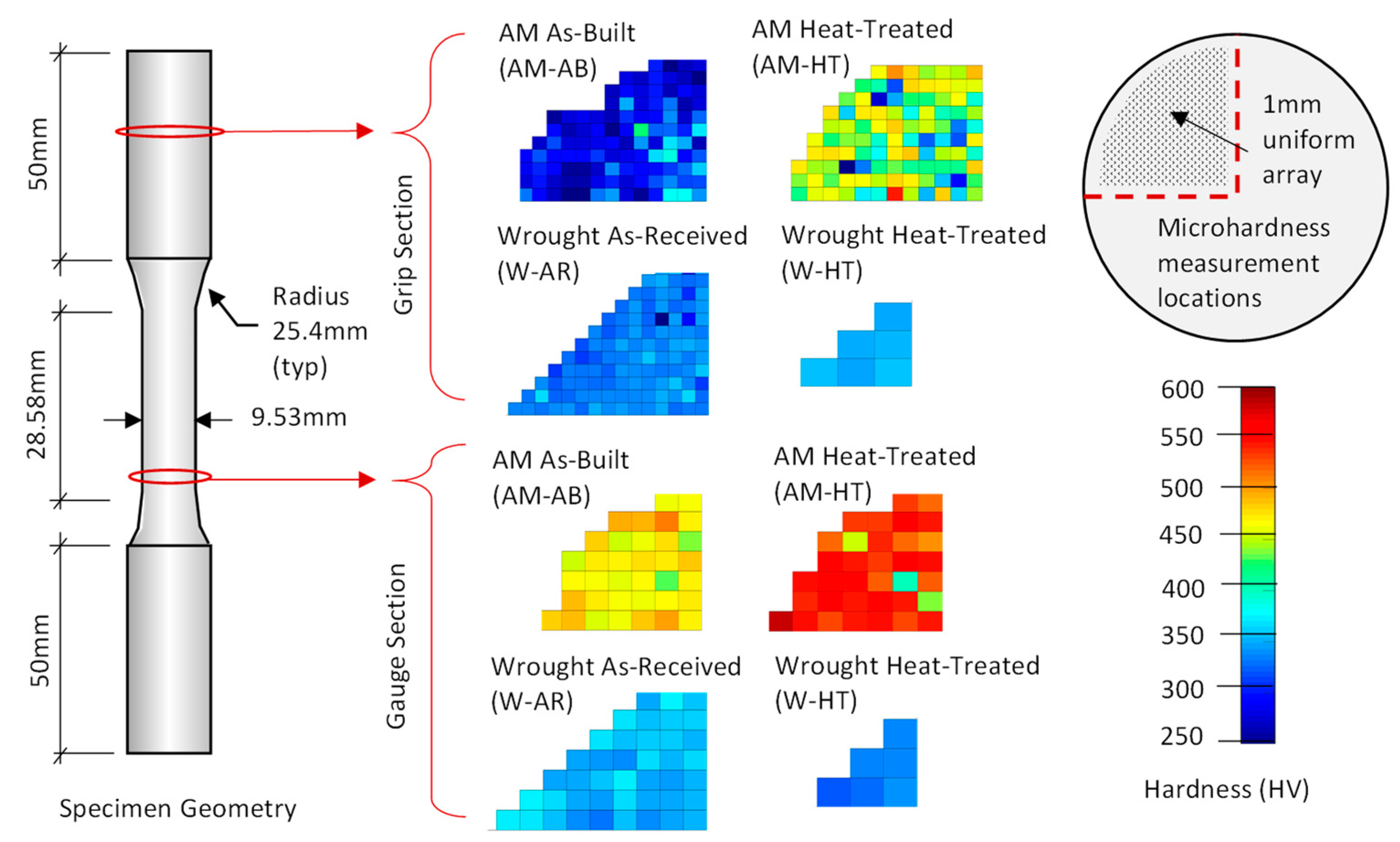
3.2. Results from Micro-Hardness Investigations

Micro-hardness testing throughout the specimen cross-sections suggests microstructure and phase changes during loading for the AM-AB and AM-HT samples, specifically in martensite and austenite content. Figure 2 shows the micro-hardness measurement contours within the gauge and grip regions for the AM and wrought steel specimens (for both heat-treated and non-heat-treated conditions). Hardness measurement comparisons between the strained gauge region and unstrained grip region indicate increased strain hardening for the AM steel specimens (as compared to the wrought steel specimens). This AM steel increase in hardness is due to strain-induced martensite formation within the gage length during plastic deformation (having more austenite-to-martensite phase change). Grip and gauge region hardness measurements from the wrought samples were similar, suggesting an already martensite dominated grain structure prior to loading. Hardness measurements between the grip and gauge regions for the AM-AB samples increased by 51.2% while the AM-HT specimens increased by 29.5%. It is important to note however, that both microstructure and material phase affect hardness. Rapid solidification during the AM steel fabrication process resulted in finer microstructural features as compared with those in the wrought steels and resulted in initial hardness values that were similar to those in the wrought steels (note the grip region hardness values in Table 2), even though the AM materials had increased austenite content.

3.3. Results from XRD Phase Analysis

Results from XRD analyses confirm microstructural phase differences between the AM and wrought steel specimens. Results from the XRD phase analysis show the presence of both martensite and austenite phases within the AM microstructure, and mostly martensite (near no presence of austenite phase) within the wrought steel microstructure. Figure 5 shows the XRD spectra for the AM and wrought specimens, with the austenite peaks within the AM steels clearly visible. Also evident from Figure 5 is that heat treatment slightly increased the austenite phase peak for the W-HT samples. Increased austenite phase for the AM-AB specimens explains the higher elongation to failure and lower material hardness within the grip area for the AM-HT specimens during monotonic tension testing. The heat treatment resulted in an increased martensite phase, which helps explain the reduction in elongation at failure and the increase UTS shown in Table 2. Micrographs also shown in Figure 5 indicate a difference in microstructure.

3.4. Observations from Fatigue Testing and Effect of Heat Treatment on ULCF Performance

Table 3 shows the ULCF results for both the AM and wrought 17-4 PH stainless steel specimens (with and without heat treatment) and Figure 6 shows the resulting fatigue-life curves. From Table 3 (shown graphically in Figure 6) the wrought specimens consistently achieved a higher fatigue life when compared with the AM counterparts. For the high strain amplitude cycles, a fatigue-life reduction of nearly 65% on average was observed for the AM fabricated steel. At lower strain amplitudes (3% strain), the observed decrease in fatigue life due to AM fabrication was 62% on average. For the lowest considered strain amplitude which entered into the LCF regime (resulting in fatigue lives greater than 100 cycles), fatigue performance of the AM and wrought specimens were similar.
Reductions in ULCF performance for the AM 17-4 PH steel can be attributed to fabrication defects resulting from the powder SLM process. Scanning electron microscopy investigations of the sample fracture surfaces found AM fabrication defects (likely due to gas entrapment and un-melted particles) of between 150–200 μm as shown in Figure 7a. Figure 7b shows a computerized tomography (CT) scan image of the unstrained AM-AB grip region having distributed void defects of up to 115 μm (in volume equivalent sphere diameter). Material defects in the wrought specimen resulting from inclusions were measured to be between 20–30 μm in size, as shown in Figure 8. Because ULCF fracture processes initiate from internal void growth and linking, the larger internal defects observed in the AM samples could be expected to grow and coalesce into micro-cracks within fewer fatigue cycles than the wrought counterparts. At the lower applied strain ranges (around the 2% strain amplitude loading), data suggest that there may be a failure mechanism transition wherein AM fabrication defects play a reduced role in fracture formation (over other processes wherein conditions between the AM and wrought microstructure conditions are similar).
Although heat treatment was shown to influence the tensile mechanical properties of the AM specimens (yield, strain at fracture, etc.), results indicate a negligible influence on the fatigue performance within the ULCF regime. This result within the ULCF regime is interesting, as it differs from results obtained by Yadollahi et al. [14] where heat-treated specimens having higher UTS outperformed AM-as-built samples in the LCF regime. The effect of heat treatment (and resulting martensite-phase influence) on AM-HT 17-4 steel performance during high strain-amplitude ULCF loading is likely overshadowed by the internal void defect deformations which precipitate internal micro-cracks. With large (on the order of 100 μm) internal voids from fabrication processes governing the ULCF fracture initiation behavior, improvement in tensile material properties from treatment processes likely do not result in an improvement in ULCF performance for AM metals.

3.5. Observations of ULCF Initiation Mechanisms from Fractographic Investigations

Fractographic investigations using scanning electron microscopy revealed material porosity, internal cracks, and un-melted pockets of metal powder in the AM SLM 17-4 PH steel specimens, while a dimpled fracture surface typical of micro void coalescence during ductile fracture was observed in the wrought 17-4 PH specimens. Figure 9 shows the fractographic images of the specimen fracture surfaces following fatigue cycles at 4% strain amplitude. In Figure 9, the AM-AB material shows elongated pockets containing un-melted metal particles while the AM-HT fracture surfaces contain a more textured surface, showing porosity, internal cracking, and semi-cleavage fracture characteristic of a brittle fracture. Note that fracture surface features are more pronounced in the tensile specimens, as compared to the reversed cycle fatigue specimens. Figure 10 shows the tensile specimen fracture surface features with several pores observable in the AM-AB specimens, and internal cracking or decohesion due to poor melting observable in the AM-HT specimens. Also shown in Figure 10 is the internal cracking within the W-HT specimens.

3.6. AM 17-4 PH Fatigue-Life Comparison with Existing LCF Prediction Models

Existing LCF prediction models often relate monotonic material properties (such as yield strength, fracture strain, elastic modulus, etc.) to cyclic material performance using assumed void growth mechanics and empirically derived strain-cycle relationships [19,25,26,27,28]. The Coffin–Manson equation (provided in Equation (1)) [29,30] is one widely used LCF prediction model for steel materials that has provided promising predictive results in many studies [31,32,33]; however, it is unclear if the monotonic properties in Equation (1) apply to ULCF prediction for AM steel materials having large fabrication void defects. Considering the coefficients in Equation (1) (σ’f, ε’f, b, and c) to be those presented in Manson’s universal slopes equation [34] ( σ f = 1.9 σ u , ε f = 0.76 [ l n ( 1 1 R A ) ] 0.6 0.76 ε f , b = −0.12, and c = −0.6) provides a fatigue-life estimation equation based on material ultimate stress (σu), fracture strain (εf), and elastic modulus (E) as shown in Equation (2).
ε i 2 = σ f E ( 2 N i ) b + ε f ( 2 N i ) c
ε i = 3.5 σ u E ( N i ) 0.12 + ε f 0.6 ( N i ) 0.6
Figure 11 compares the AM17-4 PH and wrought steel fatigue performance with that predicted in Equation (2) from the AM17-4 PH monotonic material properties. From Figure 11, the universal slopes equation over-predicts the AM steel fatigue life by between 119% and 213% on average at an applied strain amplitude of 3% and 4% respectively. In Figure 11, the Coffin–Manson fatigue life prediction more closely matches the fatigue performance of the wrought specimens having fewer internal fabrication voids.
With the inaccuracies demonstrated by Equation (2), and given the scale of the observed AM material voids formed during fabrication (see again Figure 7), an empirical fatigue-life prediction approach is proposed herein. Equation (3), represents a power-law relationship between applied strain amplitude and the number of cycles for specimen failure (defined as complete fracture of the material cross-section) fit to the mean of the measured AM fatigue data gathered in this study. In Equation (3), the strain-based ULCF prediction requires only the input of applied strain-amplitude as is valid within the ULCF and LCF regimes.
N f = ( ε 2 6.5 ) 5.15
To verify the predictive capabilities of Equation 3, two additional AM-HT specimens (designated V1 and V2) were fatigue tested at 3.5% strain amplitude under the same material characterization procedures described earlier. Figure 12 shows the resulting material response to the 3.5% strain amplitude cyclic loading, with specimens V1 and V2 completely fracturing during the 19th cycle and 24th cycle respectively. Note that from the proposed ULCF capacity curve in Equation (3) provides a reasonable estimation of fatigue life, predicting 24 cycles for the AM17-4 specimens subjected to an applied strain amplitude of 3.5%.
While the number of AM samples considered in this study is a limitation (note the AM steel specimens are currently rather expensive to produce), the ULCF predictive equation provided in Equation (3) does provide a baseline for future AM 17-4 PH steel component design where large cyclic inelastic strains are expected. As an example, in the design of future seismic structural fuse geometries, Equation (3) will better provide initial estimations for ULCF damage accumulation than current models and allow performance optimization through strain-amplitude control in AM components. Future investigations providing additional fatigue data points for AM 17-4 PH steels will help refine the proposed Equation (3).

4. Conclusions

This study compared the ULCF behavior of 17-4 PH stainless steel produced through SLM AM processes with traditionally material fabrication processes. In this study, AM-HT 17-4 PH, AM-AB 17-4 PH, and wrought 17-4 PH stainless steel specimens were investigated in ULCF under fully-reversed (R= −1) strain-controlled conditions to better understand mechanisms affecting ULCF performance. Additional material tensile characterization tests were conducted to investigate material tensile property relationships and ULCF behavior. To help identify ULCF mechanisms leading to fracture, each sample was investigated using scanning electron microscopy, micro-hardness testing, computer tomography (CT) scanning, and XRD. A simple empirical model is developed to allow estimation of ULCF life in AM 17-4 PH components. The following conclusions are based on material testing observations and measurements:
1.
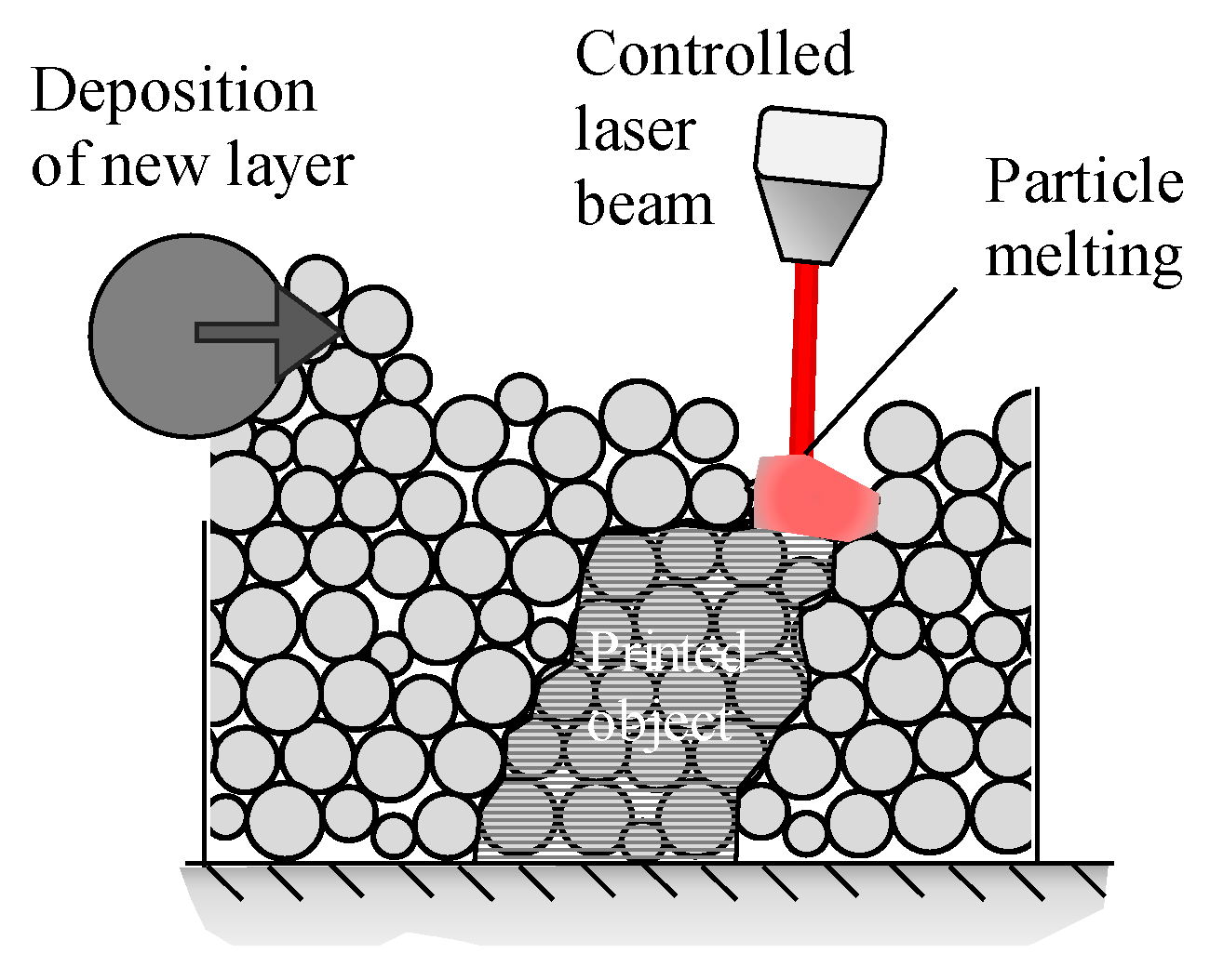
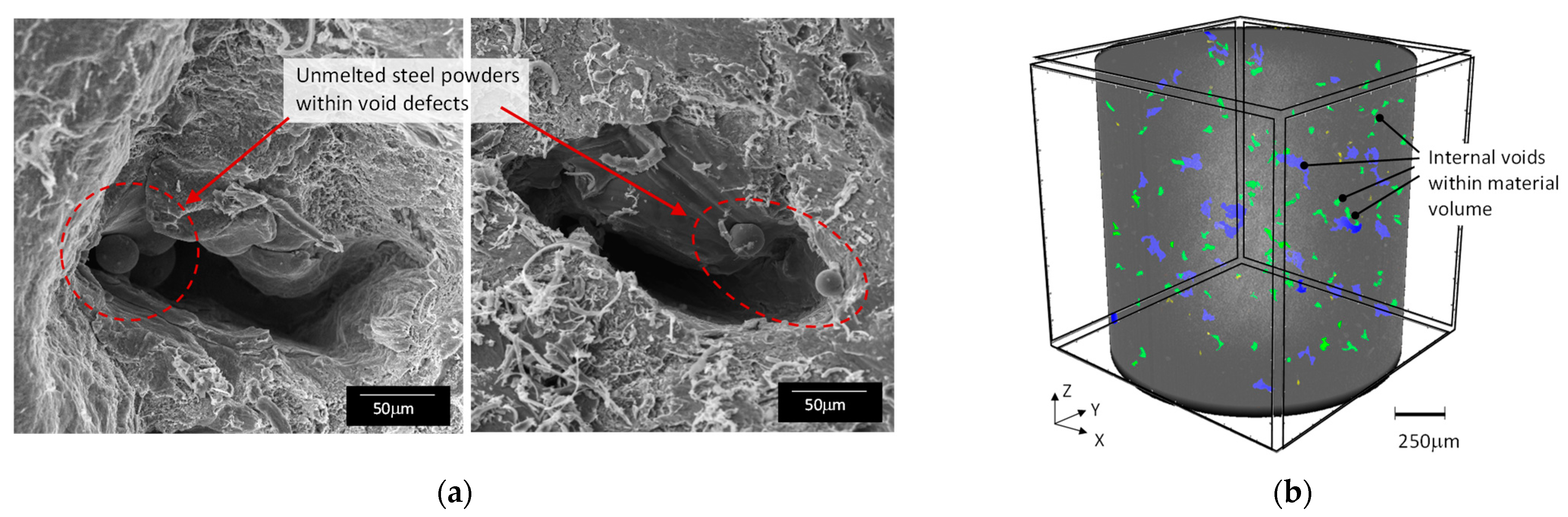
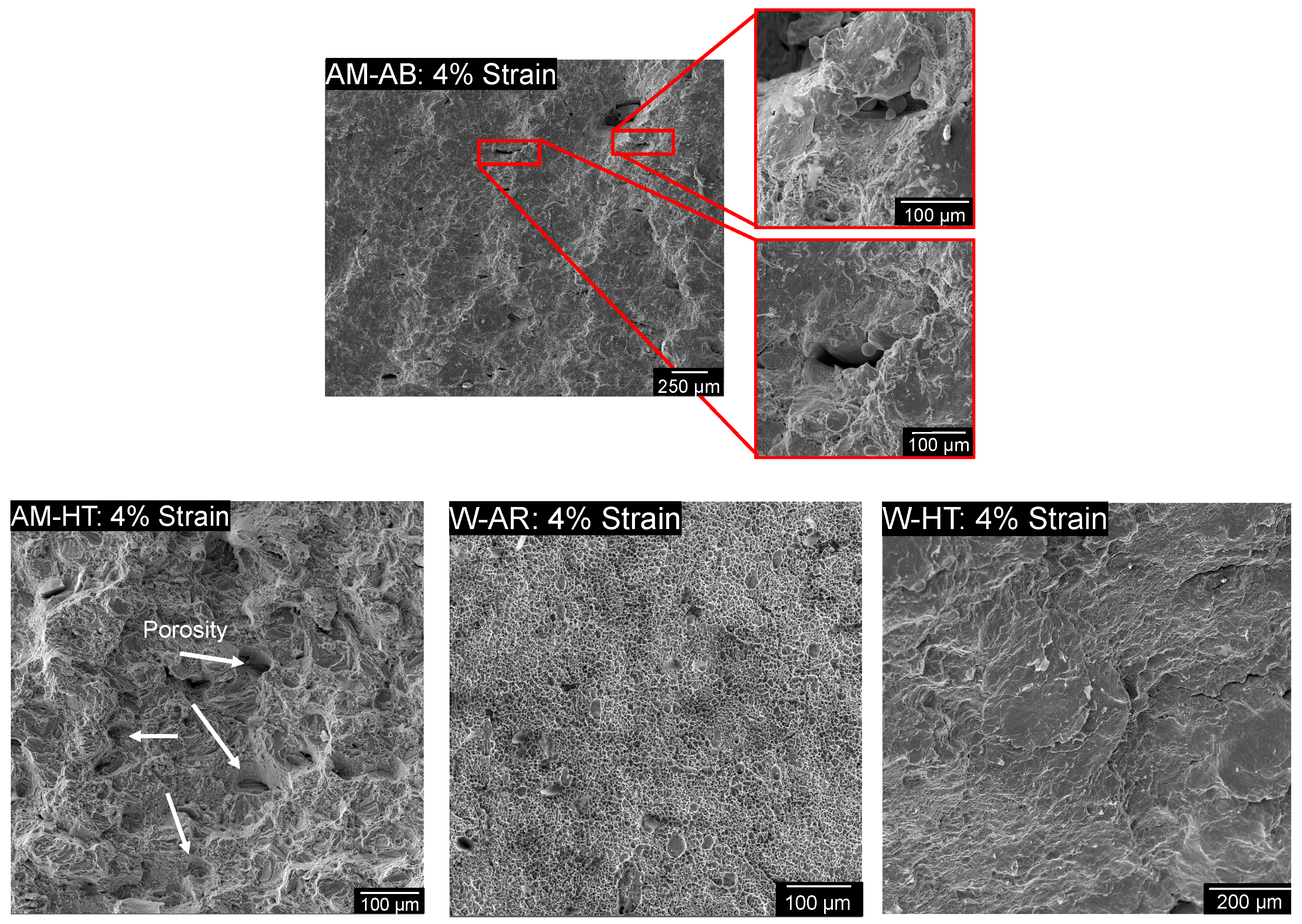
SLM AM fabrication processes result in un-melted particles and gas entrapment which can create internal material voids on the order of 100 to 200 μm.
2.
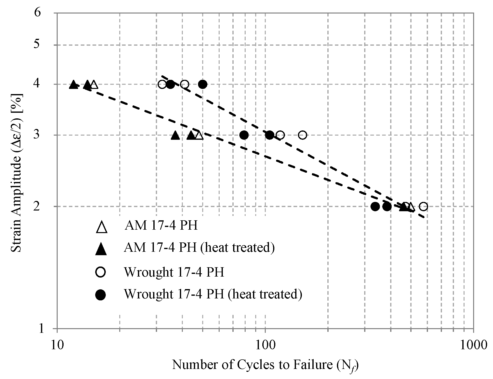
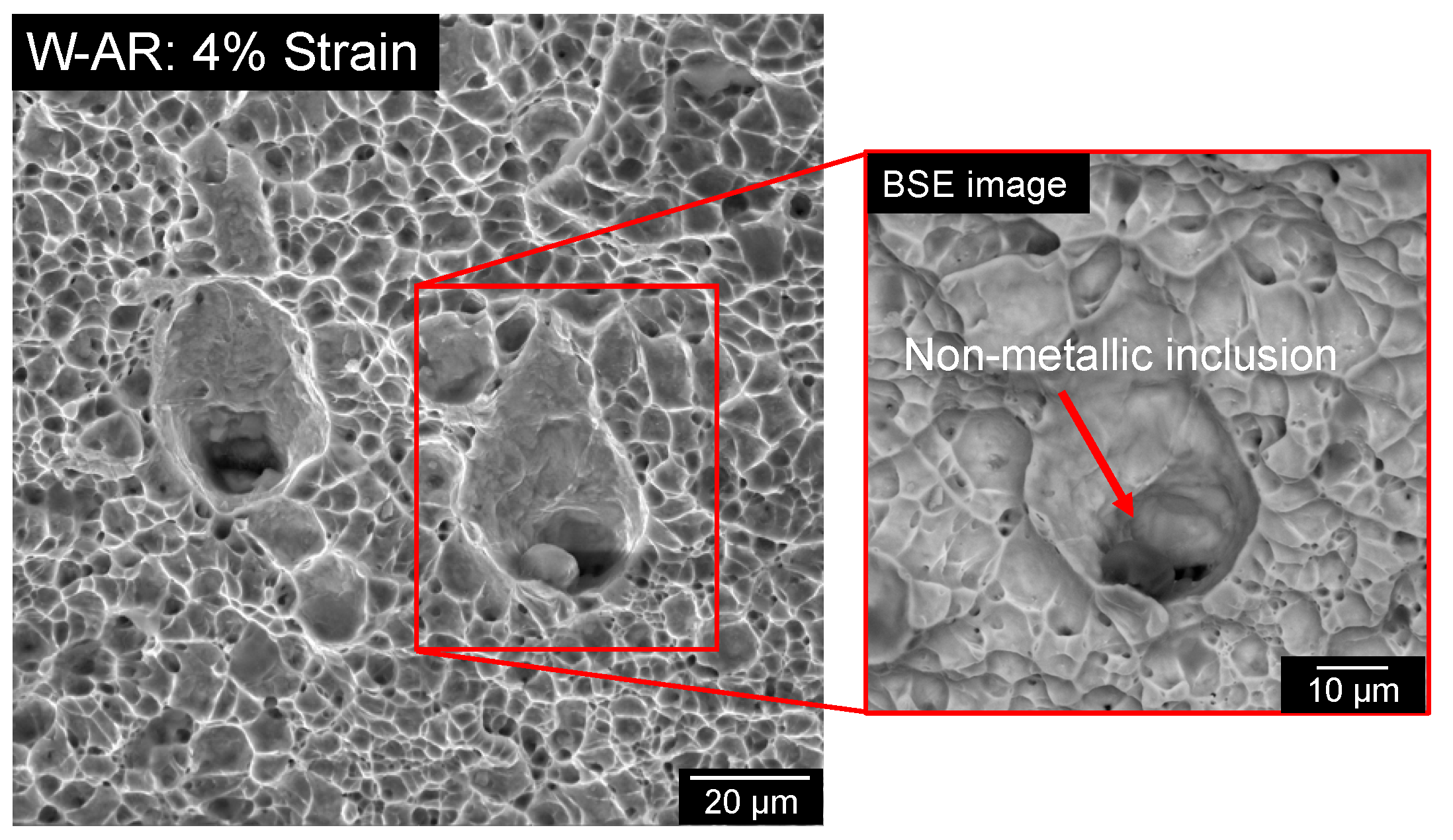
Large internal void defects result in decreased ULCF performance for AM 17-4 PH steel specimens as compared to the wrought steel counterparts, which have inclusion defects of approximately 20 μm. A decrease in fatigue life of between 62% and 65% was observed at strain amplitudes of 3% and 4%, respectively.
3.
Within the LCF regime (Nf > 100, resulting from strain amplitudes near 2%), fatigue behavior of the AM and wrought steel specimens are similar.
4.
Post fabrication heat treatment processes done in this work have no observable effect on the ULCF or LCF behavior of AM 17-4 PH stainless steel materials. Although heat treatment processes were found to alter the AM material tensile properties (yield, strain hardening, etc.), the ULCF behavior of heat-treated and non-heat-treated AM 17-4 PH stainless steels were similar (likely due to the fatigue processes being governed by void/defect size).
5.
The existing Coffin–Manson universal slopes equation for LCF prediction over-estimated the fatigue life of the AM specimens at applied strain amplitudes of 3% and 4%. Fatigue-life predictions at the 3% and 4% strain amplitudes were over-estimated by 119% and 213%, respectively.
6.
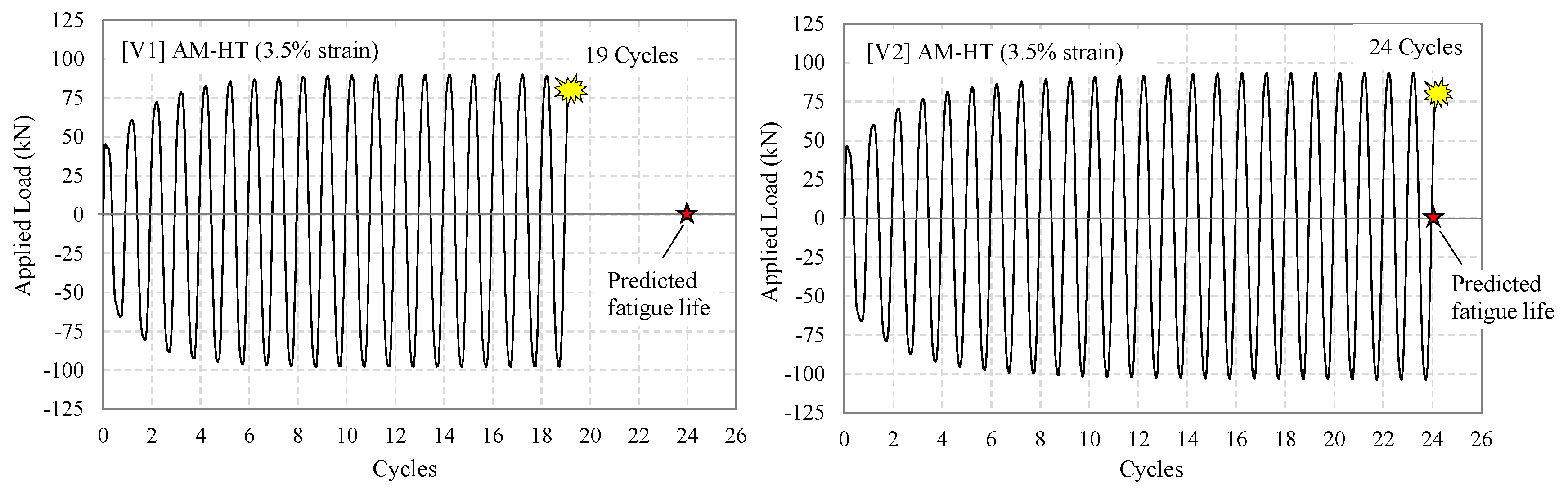
An empirical ULCF capacity equation for AM 17-4 PH stainless steel is proposed herein. Additional testing demonstrated good agreement with the proposed equation predictions (providing fatigue-life estimations within 10% on average between the two additional verification tests). Future ULCF testing would be beneficial in further refining the proposed empirical model.

Author Contributions

Conceptualization, G.S.P.; methodology, D.G.-N., G.S.P. and T.S.; formal analysis, D.G.-N., T.S. and G.S.P.; investigation, D.G.-N., T.S. and G.S.P.; resources, G.S.P.; data curation, D.G.-N., T.S. and G.S.P.; writing—original draft preparation, D.G.-N., T.S. and G.S.P.; writing—review and editing, D.G.-N. and G.S.P.; visualization, D.G.-N. and G.S.P.; supervision, G.S.P.; funding acquisition, G.S.P. All authors have read and agreed to the published version of the manuscript.

Funding

This research was funded by the US National Science Foundation, grant number 1751699.

Institutional Review Board Statement

Not applicable.

Informed Consent Statement

Not applicable.

Data Availability Statement

All data generated or used during the study are available from the corresponding author by request.

Acknowledgments

This material is based upon work supported by the US National Science Foundation under Grant No. 1751699. In-kind support of AM material specimens provided by the National Institute of Standards and Technology (NIST) as well as specimen CT-scanning assistance provided by the US Army Corps Engineering Research and Development Center (ERDC) is acknowledged and greatly appreciated.

Conflicts of Interest

The authors declare no conflict of interest.

References

  1. Carlton, H.D.; Haboub, A.; Gallegos, G.F.; Parkinson, D.Y.; MacDowell, A.A. Damage Evolution and Failure Mechanisms in Additively Manufactured Stainless Steel. Mater. Sci. Eng. A 2016, 651, 406–414. [Google Scholar] [CrossRef] [Green Version]
  2. Bao, J.; Wu, S.; Withers, P.J.; Wu, Z.; Li, F.; Fu, Y.; Sun, W. Defect Evolution during High Temperature Tension-Tension Fatigue of SLM AISi10Mg Alloy by Synchrotron Tomography. Mater. Sci. Eng. A 2020, 792, 139809. [Google Scholar] [CrossRef]
  3. Haghdadi, N.; Laleh, M.; Moyle, M.; Primig, S. Additive Manufacturing of Steels: A Review of Achievements and Challenges. J. Mater. Sci. 2021, 56, 64–107. [Google Scholar] [CrossRef]
  4. Karthik, G.M.; Kim, H.S. Heterogeneous Aspects of Additive Manufactured Metallic Parts: A Review. Met. Mater. Int. 2021, 27, 1–39. [Google Scholar] [CrossRef]
  5. Zhao, L.; Santos Macías, J.G.; Douillard, T.; Li, Z.; Simar, A. Unveiling Damage Sites and Fracture Path in Laser Powder Bed Fusion AlSi10Mg: Comparison between Horizontal and Vertical Loading Directions. Mater. Sci. Eng. A 2021, 807, 140845. [Google Scholar] [CrossRef]
  6. Ben, D.D.; Ma, Y.R.; Yang, H.J.; Meng, L.X.; Shao, X.H.; Liu, H.Q.; Wang, S.G.; Duan, Q.Q.; Zhang, Z.F. Heterogeneous Microstructure and Voids Dependence of Tensile Deformation in a Selective Laser Melted AlSi10Mg Alloy. Mater. Sci. Eng. A 2020, 798, 140109. [Google Scholar] [CrossRef]
  7. Shifeng, W.; Shuai, L.; Qingsong, W.; Yan, C.; Sheng, Z.; Yusheng, S. Effect of Molten Pool Boundaries on the Mechanical Properties of Selective Laser Melting Parts. J. Mater. Process. Technol. 2014, 214, 2660–2667. [Google Scholar] [CrossRef]
  8. Xiong, Z.H.; Liu, S.L.; Li, S.F.; Shi, Y.; Yang, Y.F.; Misra, R.D.K. Role of Melt Pool Boundary Condition in Determining the Mechanical Properties of Selective Laser Melting AlSi10Mg Alloy. Mater. Sci. Eng. A 2019, 740–741, 148–156. [Google Scholar] [CrossRef]
  9. LeBrun, T.; Nakamoto, T.; Horikawa, K.; Kobayashi, H. Effect of Retained Austenite on Subsequent Thermal Processing and Resultant Mechanical Properties of Selective Laser Melted 17–4 PH Stainless Steel. Mater. Des. 2015, 81, 44–53. [Google Scholar] [CrossRef]
  10. Liverani, E.; Toschi, S.; Ceschini, L.; Fortunato, A. Effect of Selective Laser Melting (SLM) Process Parameters on Microstructure and Mechanical Properties of 316L Austenitic Stainless Steel. J. Mater. Process. Technol. 2017, 249, 255–263. [Google Scholar] [CrossRef]
  11. Mahmoudi, M.; Elwany, A.; Yadollahi, A.; Thompson, S.M.; Bian, L.; Shamsaei, N. Mechanical Properties and Microstructural Characterization of Selective Laser Melted 17-4 PH Stainless Steel. Rapid Prototyp. J. 2017, 23, 280–294. [Google Scholar] [CrossRef] [Green Version]
  12. Mower, T.M.; Long, M.J. Mechanical Behavior of Additive Manufactured, Powder-Bed Laser-Fused Materials. Mater. Sci. Eng. A 2016, 651, 198–213. [Google Scholar] [CrossRef]
  13. Brodie, E.G.; Richter, J.; Wegener, T.; Niendorf, T.; Molotnikov, A. Low-Cycle Fatigue Performance of Remelted Laser Powder Bed Fusion (L-PBF) Biomedical Ti25Ta. Mater. Sci. Eng. A 2020, 798, 140228. [Google Scholar] [CrossRef]
  14. Yadollahi, A.; Shamsaei, N.; Thompson, S.M.; Elwany, A.; Bian, L. Effects of Building Orientation and Heat Treatment on Fatigue Behavior of Selective Laser Melted 17-4 PH Stainless Steel. Int. J. Fatigue 2017, 94, 218–235. [Google Scholar] [CrossRef]
  15. Yadollahi, A.; Shamsaei, N. Additive Manufacturing of Fatigue Resistant Materials: Challenges and Opportunities. Int. J. Fatigue 2017, 98, 14–31. [Google Scholar] [CrossRef] [Green Version]
  16. Rafi, H.K.; Pal, D.; Patil, N.; Starr, T.L.; Stucker, B.E. Microstructure and Mechanical Behavior of 17-4 Precipitation Hardenable Steel Processed by Selective Laser Melting. J. Mater. Eng. Perform. 2014, 23, 4421–4428. [Google Scholar] [CrossRef]
  17. Huo, C.Y.; Gao, H.L. Strain-Induced Martensitic Transformation in Fatigue Crack Tip Zone for a High Strength Steel. Mater. Charact. 2005, 55, 12–18. [Google Scholar] [CrossRef]
  18. Kanvinde, A.M.; Deierlein, G.G. Continuum Based Micro-Models for Ultra Low Cycle Fatigue Crack Initiation in Steel Structures. In Proceedings of the Structures Congress 2005, 18 April 2005; American Society of Civil Engineers: Reston, VA, USA, 2005. [Google Scholar] [CrossRef]
  19. Kanvinde, A.M.; Deierlein, G.G. Cyclic Void Growth Model to Assess Ductile Fracture Initiation in Structural Steels Due to Ultra Low Cycle Fatigue. J. Eng. Mech. 2007, 133, 701–712. [Google Scholar] [CrossRef]
  20. Pereira, J.C.R.; de Jesus, A.M.P.; Xavier, J.; Fernandes, A.A. Ultra Low-Cycle Fatigue Behaviour of a Structural Steel. Eng. Struct. 2014, 60, 214–222. [Google Scholar] [CrossRef]
  21. Yonekura, D.; Arai, Y.; Komotori, J.; Shimizu, M. Fracture Mechanism of Ferritic Ductile Cast Iron in Extremely Low Cycle Fatigue. Jpn. Soc. Mech. Eng. Part A. 1999, 65, 821–826. [Google Scholar] [CrossRef] [Green Version]
  22. Prinz, G.S.; Richards, P.W. Demands on Reduced Beam Section Connections with Out-of-Plane Skew. J. Struct. Eng. 2016, 142, 04015095. [Google Scholar] [CrossRef]
  23. Desrochers, C.; Prinz, G.S.; Richards, P.W. Column Axial Load Effects on the Performance of Skewed SMF RBS Connections. J. Constr. Steel Res. 2018, 150, 505–513. [Google Scholar] [CrossRef]
  24. ASTM Standard E 606-12–Standard Practice for Strain-Controlled Fatigue Testing; American Society for Testing and Materials, Int.: West Conshohocken, PA, USA, 2012.
  25. Kanvinde, A.M.; Deierlein, G.G. Validation of Cyclic Void Growth Model for Fracture Initiation in Blunt Notch and Dogbone Steel Specimens. J. Struct. Eng. 2008, 134, 1528–1537. [Google Scholar] [CrossRef]
  26. Rice, J.R.; Tracey, D.M. On the Ductile Enlargement of Voids in Triaxial Stress Fields∗. J. Mech. Phys. Solids 1969, 17, 201–217. [Google Scholar] [CrossRef] [Green Version]
  27. Wen, H.; Mahmoud, H. New Model for Ductile Fracture of Metal Alloys. II: Reverse Loading. J. Eng. Mech. 2016, 142, 04015089. [Google Scholar] [CrossRef]
  28. Kanvinde, A.M.; Deierlein, G.G. Micromechanical Simulation of Earthquake-Induced Fracture in Steel Structures; Stanford University: Stanford, CA, USA, 2004. [Google Scholar]
  29. Coffin, L.F., Jr. A Study of the Effects of Cyclic Thermal Stresses in Ductile Metals. ASME 1954, 76, 931–950. [Google Scholar]
  30. Manson, S.S. Behavior of Materials under Conditions of Thermal Stress. National Advisory Committee for Aeronautics. Report No. 1170. 1953.
  31. Prinz, G.S.; Coy, B.; Richards, P.W. Experimental and Numerical Investigation of Ductile Top-Flange Beam Splices for Improved Buckling-Restrained Braced Frame Behavior. J. Struct. Eng. 2014, 140, 04014052. [Google Scholar] [CrossRef] [Green Version]
  32. de Castro e Sousa, A. Ultra Low Cycle Fatigue of Welded Steel Joints under Multiaxial Loading. Ph.D. Thesis, Ecole Polytechnique Federale de Lausanne (EPFL), Lausanne, Switzerland, 2017. [Google Scholar]
  33. de Castro e Sousa, A.; Nussbaumer, A. Multiaxial Ultra Low Cycle Fatigue in Welded High Strength Steel Structural Components. J. Constr. Steel Res. 2019, 153, 473–482. [Google Scholar] [CrossRef]
  34. Manson, S.S. Fatigue: A Complex Subject—Some Simple Approximations. Exp. Mech. 1965, 5, 193–226. [Google Scholar] [CrossRef]
Figure 1. Selective laser melting additive manufacturing process illustration.
Metals 11 01726 g001
Figure 2. Specimen dimensions and micro-hardness test measurements from gauge and grip locations.
Metals 11 01726 g002
Figure 3. Experimental set-up.
Metals 11 01726 g003
Figure 4. Illustration of specimen build direction relative to the applied loading direction.
Metals 11 01726 g004
Figure 5. XRD spectra and micrograph from within the un-strained grip location.
Metals 11 01726 g005
Figure 6. Fully reversed (R = −1) strain-life fatigue curves for 17-PH AM-AB, AM-HT, W-AR, and W-HT steels.
Metals 11 01726 g006
Figure 7. Voids due to un-melted metal powder in an AM-AB specimen: (a) SEM fractograph, and (b) CT scan of unstrained (grip location).
Metals 11 01726 g007
Figure 8. Non-metallic inclusion in W-AR sample. Right: Backscattered electron image of the inclusion.
Metals 11 01726 g008
Figure 9. Fracture surface of sample subjected to fatigue testing at 4% strain.
Metals 11 01726 g009
Figure 10. Sample fracture surface resulting from uni-directional tension test.
Metals 11 01726 g010
Figure 11. Coffin–Manson universal slopes comparison to measured fatigue data and proposed ULCF regression.
Metals 11 01726 g011
Figure 12. Verification results from the proposed empirical ULCF Equation.
Metals 11 01726 g012
Table 1. Metal powder chemical composition.
TypeCr (wt%)Ni (wt%)Cu (wt%)Mn (wt%)Si (wt%)Mo (wt%)Nb (wt%)C (wt%)
Nominal Values15–17.53–53–5Max. 1Max. 1Max. 0.50.15–0.45Max. 0.07
Table 2. Tension and micro-hardness material characterization results.
Sample DescriptionMaterial TypeFracture Strain (εf)Yield Stress (σy (0.2%)) (MPa)Ultimate Stress (σu) (MPa)Vickers Hardness (HV)
GripGage
Wrought—as receivedW-AR0.1538811060335356
Wrought—heat treatedW-HT0.1528821017356333
AM—as builtAM-AB0.1906301025294475
AM—heat treatedAM-HT0.1535121495432535
Table 3. Ultra low-cycle fatigue test results.
Material TypeSpecimen No.Strain Amplitude (Δε/2) (%)Nf (Cycles)
W-AR12384
22337
3379
43105
5435
6450
W-HT72575
82471
93118
103151
11441
12432
AM-AB132515
14347
15414
16415
AM-HT172462
18344
19337
20414
21412
Publisher’s Note: MDPI stays neutral with regard to jurisdictional claims in published maps and institutional affiliations.

