Article

Effect of Quenching and Partitioning Heat Treatment on the Fatigue Behavior of 42SiCr Steel

Group of Composites and Material Compounds, Institute of Materials Science and Engineering (IWW), Chemnitz University of Technology, 09125 Chemnitz, Germany
*
Author to whom correspondence should be addressed.
Metals 2021, 11(11), 1699; https://doi.org/10.3390/met11111699
Submission received: 9 September 2021 / Revised: 15 October 2021 / Accepted: 22 October 2021 / Published: 25 October 2021

Abstract

:
The manufacturing of advanced high-strength steels with enhanced ductility is a persistent aim of research. The ability of a material to absorb high loads while showing a high deformation behavior is a major task for many industrial fields like the mobility sector. Therefore, the material properties of advanced high-strength steels are one of the most important impact factors on the resulting cyclic fatigue behavior. To adjust advanced material properties, resulting in high tensile strengths as well as an enhanced ductility, the heat treatment process of quenching and partitioning (QP) was developed. The quenching takes place in a field between martensite start and martensite finish temperature and the subsequent partitioning is executed at slightly elevated temperatures. Regarding the sparsely investigated field of fatigue research on quenched and partitioned steels, the present work investigates the influence of a QP heat treatment on the resulting microstructure by light and scanning electron microscopy as well as on the mechanical properties such as tensile strength and resistance against fatigue regarding two different heat treatment conditions (QP1, QP2) in comparison to the cold-rolled base material of 42SiCr steel. Therefore, the microscopic analysis proved the presence of a characteristic quenched and partitioned microstructure consisting of a martensitic matrix and partial areas of retained austenite, whereas carbides were also present. Differences in the amount of retained austenite could be observed by using X-ray diffraction (XRD) for the different QP routes, which influence the mechanical properties resulting in higher tensile strength of about 2000 MPa for QP1 compared to about 1600 MPa for QP2. Furthermore, the transition for the fatigue limit was approximated by using stepwise load increase tests (LIT) and afterwards verified by constant amplitude tests (CAT) in accordance with the staircase method, whereas the QP1 condition reached the highest fatigue strength of 900 MPa. Subsequent light and scanning electron microscopy of selected fractured surfaces and runouts showed a different behavior regarding the size of the fatigue fracture area and also differences in the microstructure of these runouts.

1. Introduction

Reaching high tensile strengths, a good ductility as well as a high resistance against fatigue are the main goals for modern materials. Hence, not only are polymer matrix composites of central interest of industry and research, even the field of metals, especially of steels, is undergoing progress over several years leading to the development of beneficial advanced high-strength steels (AHSS). Along with the evolution of such innovative materials, also the sector of mechanical testing was extended over the last two decades. Regarding the fatigue behavior of metals, the model of the WOEHLER curve was extended from low cycle fatigue (LCF) and high cycle fatigue (HCF) to the very high cycle fatigue (VHCF) range, indicating that often the fatigue limit decreases further after 108 cycles [1]. Furthermore, the comparatively high amount of time that is consumed by fatigue investigations can be reduced by the use of innovative methods like, e.g., the PHYBAL principle [2]. This principle is based on the combination of experimental and numerical methods, whereas only three fatigue tests need to be carried out. Starting with an initial stepwise load increase test (LIT), that uses the plastic strain as an indicator for the estimation of the fatigue limit and two subsequent CAT before determining stress levels of the lower and upper threshold from the LIT [3,4]. Findings like the VHCF and the PHYBAL principle are also of great industrial interest to optimize the structural design of safety-related components like railway steel wheels, e.g., investigated by Koster et al., for the unalloyed medium carbon steel SAE1050 on an ultrasonic testing facility [5].
To further push the boundaries of the physical properties of steels, innovative heat treatments can be an effective method. Therefore, the process of quenching and partitioning (QP) was developed, which results in excellently balanced properties for high tensile strength and good ductility [6,7,8,9]. Therefore, a steel is austenitized and afterwards quenched in a temperature range between martensite start (MS) and martensite finish (MF) temperature before isothermal partitioning at temperatures between MS and quenching for a defined time. By passing this QP process, the microstructure of the steel develops a basically martensitic characteristic with a defined amount of stabilized retained austenite (RA) in lamellar, blocky or thin film-like form ranging from 5–20 wt% [10,11]. The major advantage of this QP microstructure is an advanced tensile strength reaching values of about 2000 MPa as well as elongations up to 15% [10,12,13,14]. An important fact, therefore, is the chemical composition of the material. The carbon (C) content as well as alloying elements like silicon (Si), chrome (Cr) and manganese (Mn) influence the QP process and the stability of the retained austenite. The amount of carbon regulates the MS and MF temperature. After the quenching, the force-solved carbon diffuses while partitioning from the martensite into the retained austenite, which results in a stabilization of the retained austenite (RA). Therefore, the silicon content is an important factor by preventing the formation of brittle carbide precipitations due to its low solubility in carbides [12]. Chrome delays the formation of pearlite and bainite and further enhances the hardenability and resistance against tempering of the material [10]. Additionally, Mn improves the solubility of carbon in the austenite and retards the formation of pearlite [15].
By taking a look at the sparsely investigated field of fatigue on QP steels, most of the work reports an enhancement of the fatigue lifetime due to the quenching and partitioning process [11,14,16,17,18]. Calderon et al. investigated the influence of the microstructure on the fatigue behavior of two steels with varying carbon content, resulting in a higher volume fraction of RA leading to higher fatigue limit related to the delay of crack propagation by phase transformation of austenite to martensite [11]. Further research from Melado et al. confirmed the same main findings regarding the amount of retained austenite on the fatigue behavior [14]. Also, Cerny et al. confirmed these results in their work on the resulting fatigue behavior of 42SiCr by different heat treatments whereas the QP condition reached the highest fatigue strength of 675 MPa compared to 545 MPa for a quenched and tempered (QT) condition and 455 MPa for the base material [19].
This recent work investigates the influence of the QP heat treatment on the fatigue behavior of a 42SiCr high-strength low alloy (HSLA) steel using two QP routes in comparison to the cold-rolled condition. Light and scanning electron microscopy were used to evaluate the resulted microstructure as well as X-ray diffraction to determine the amount of retained austenite. Moreover, tensile tests and cyclic load increase tests (LIT) followed by a small number of constant amplitude tests (CAT) were performed. Additionally, scanning electron microscopy of the fatigue fracture surface and the runouts were carried out.

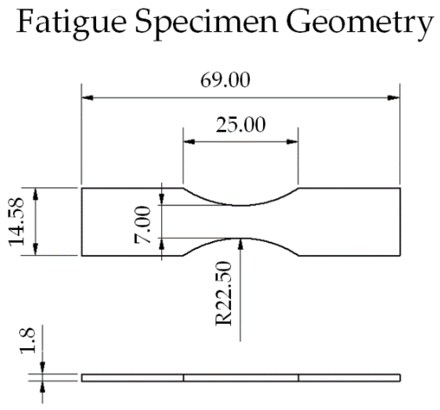
2. Materials and Methods

The chemical composition of the 42SiCr steel was detected by optical emission spectrometry and is presented in Table 1.
The contained amount of carbon, silicon, chromium and manganese, which is necessary to obtain the QP effect, is in accordance with the literature for 42SiCr. The metal sheet has a thickness of 2 mm and was investigated in three different conditions: The cold-rolled condition and two in pre-investigations selected quenched and partitioned conditions (QP1, QP2) to investigate the influence of different contents of retained austenite. Figure 1 shows the schematic temperature–time sequence for the quenching and partitioning processes for the investigated conditions QP1 and QP2.
The QP1 condition is characterized by an austenitizing (A) at 930 °C (6 min), before quenching (Q) in a salt bath at 200 °C (20–30 s) and afterwards isothermal partitioning (P) at 250 °C (10 min). QP2 is heated up to the same temperature for the equal time for austenitizing and then quenched at a higher temperature of 250 °C (20–30 s) before finally being partitioned at 380 °C (10 min).
The preparation of the joint samples for light and scanning microscopic analysis took place by cutting the material and embedding them with cold embedding resin. Afterwards, the samples got ground with MD Piano Discs in different granulation for 3 min each. Subsequently, an intermediate and final polishing was applied on the samples. Light microscopic investigations were carried out on a light microscope Olympus GX51 and for high resolution microscopy a scanning electron microscope (SEM, Leo1455VP from ZEISS, Jena, Germany) was used.
X-ray diffraction (XRD) measurements were performed by using a D8 Discover diffractometer (Bruker AXS, Billerica, MA, USA) with Co-Kα radiation (40 kV, 40 mA, point focus), a collimator with 1 mm diameter and an energy-filtered 1D Lynxeye XE detector. The diffraction diagrams were measured in the diffraction angle (2θ) range 10°–130° with a step size of 0.01° and a time of 3.4 s/step, which corresponds to 652.8 s/step due to the use of the 1 D detector. The mass fractions and the lattice parameter aγ were determined using the Rietveld method, considering device-related line-broadening effects.
The determination of the carbon content wC (mass fraction in %) in the retained austenite was calculated as a function of the lattice parameter aγ of the retained austenite by using the following equation [20]:
w C   =   a γ     0.3573   n m 0.0033   n m w t %
The tensile tests were performed on a 20 kN Zwick Roell tensile testing machine at room temperature with a strain rate of 2.5 × 10⁻⁴. The specimen geometry was shape E of DIN 50125 and three specimens of each joint were tested.
For the determination of the fatigue limit, a servo-hydraulic testing machine MTS Landmark 100 kN was used. The fatigue tests were performed force-controlled under room temperature with a stress ratio of R = 0.1 and a frequency of 5 Hz. The elongation of the specimens was determined by using a clip gage. The specimens were manufactured by water jet cutting and subsequent polished to a roughness of Ra = 0.2 µm. The geometry of the specimens was designed following DIN EN 3987 (Figure 2) [21].
The fatigue investigations were divided in stepwise load increase tests (LIT) and constant amplitude tests (CAT). Following the PHYBAL principle, the LIT were used for an accelerated estimation of the approximated fatigue strength, that should be verified afterwards by a small number of CAT following the staircase method of DIN 50,100 [22]. The number of tested specimens for each condition was three for the LIT and five for the CAT. According to the literature of the PHYBAL principle, the LIT had a number of 10,000 cycles for each step before increasing the load by 40 MPa per step [4]. A suitable initial stress level was chosen based on the results of the stress strain curves for each condition, corresponding to 40% of the respective yield strength. The materials’ measurand for the estimated fatigue lifetime of 2 × 10⁶ cycles was the plastic strain, that was calculated by subtraction of the elastic strain (also calculated from the Young’s modulus and the time-dependent present stress) from the measured total strain (measured by the clip gage). The LIT were run until the specimen failed. Afterwards, the development of the plastic strain was investigated and if a rise occurred, this number of cycles and the belonging stress level was assumed to be the estimated fatigue strength. Whenever no explicit reaction for the plastic strain curve could be detected, a third degree polynomial was used to fit the values of the plastic strain to a mathematical function according to the PHYBAL principle [2]. Afterwards, the first derivative of this function, which represented the rise of the function, was calculated and used to place tangents at its minimum (linear rise) and maximum (exponential rise), which intersect at a certain point. The number of cycles and the corresponding stress level of this intersection point of the two tangents then was presumed as the estimated fatigue limit. The step height of the stress level for the staircase method on the CAT was 50 MPa.

3. Results and Discussion

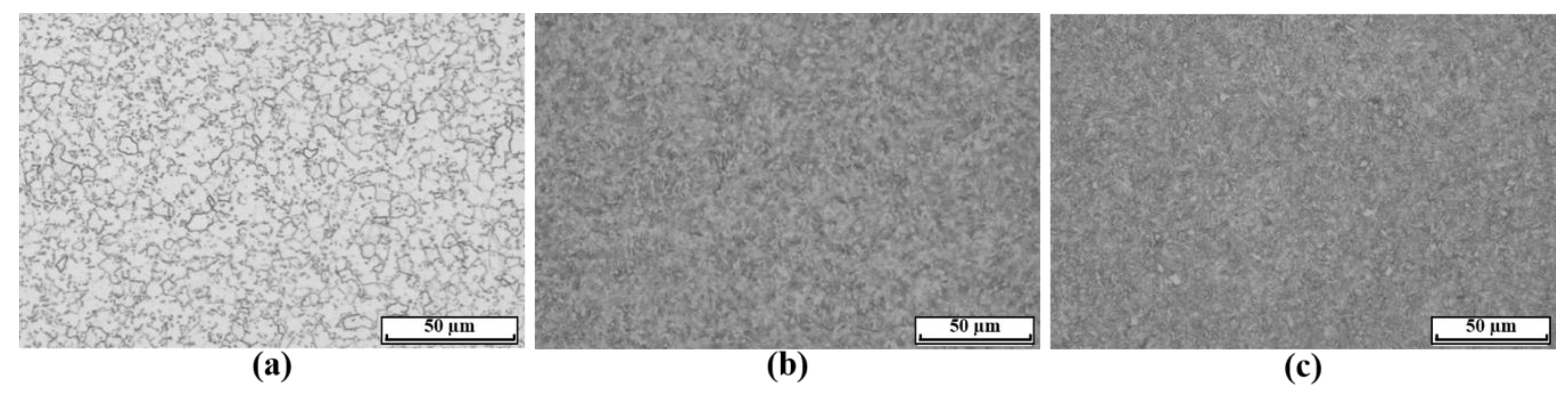
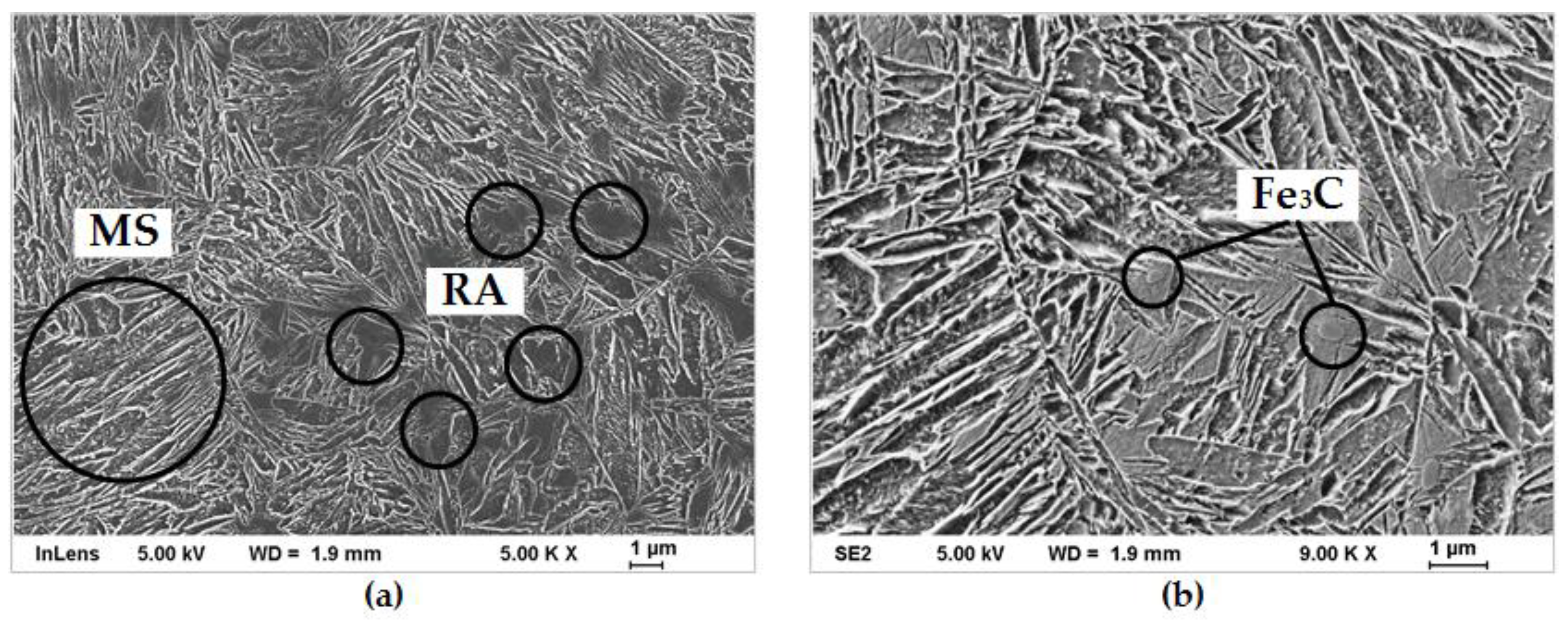
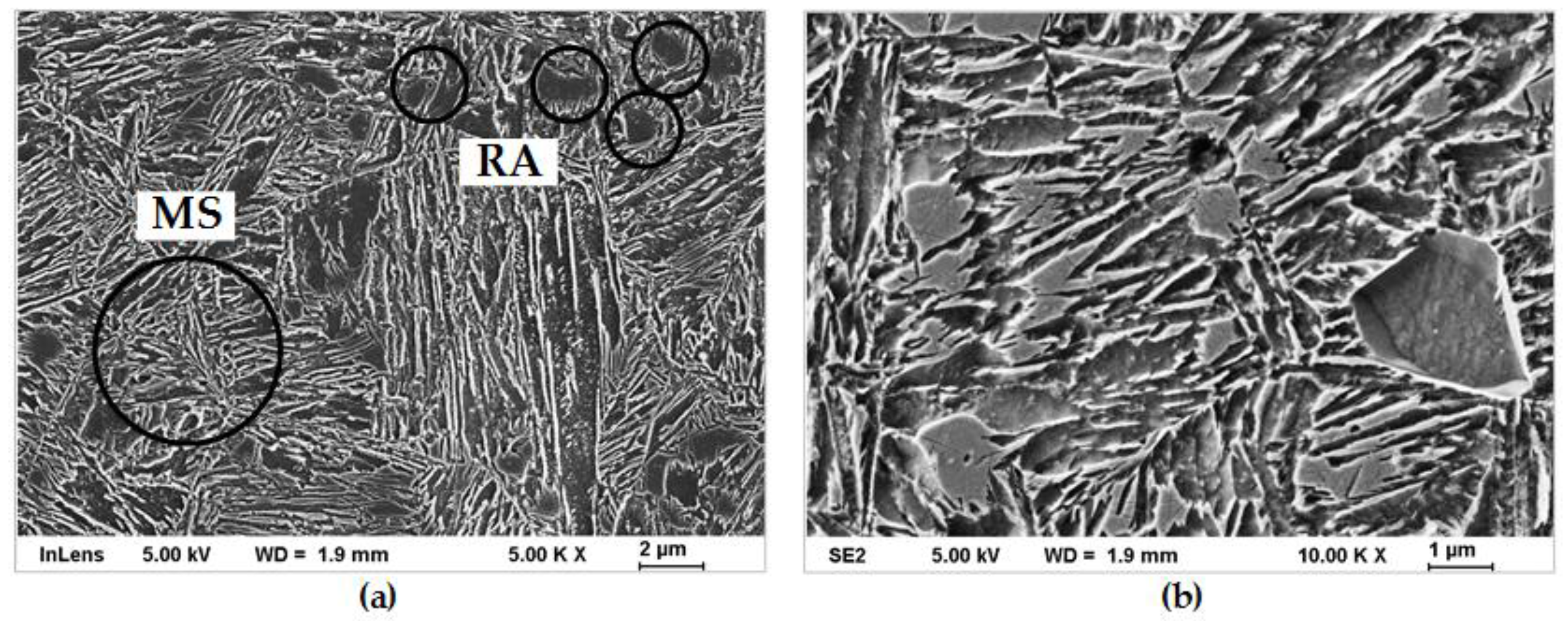
3.1. Microstructural Analysis

Light microscopic investigations showed the expected typical ferritic-perlitic microstructure for the cold-rolled condition of the 42SiCr base material, whereas the QP1 and QP2 heat treatment resulted in the targeted martensitic microstructure with an amount of retained austenite, as visible in Figure 3.
To get a more detailed analysis of the microstructural development according to the different heat treatment routes, scanning electron microscopy was carried out. Figure 4 shows a characteristic area of QP1 in different magnifications.
Figure 4a depicts the lath morphology of the martensite (bigger circle) due to the amount of carbon being less than 0.5%. Furthermore, local islands of RA (smaller circles) can be seen. Taking a closer look at the microstructure at a higher magnification, Figure 4b proves the presence of a small amount of particular globular carbides (Fe3C), what leads to the assumption that they cannot be avoided completely by the QP process. Also, Mehner et al. found minor fractions of carbides in their QP conditions [23]. In comparison to QP1, the scanning electron images of the QP2 condition are shown in Figure 5.
The QP2 route with a higher quenching temperature as well as a higher partitioning temperature resulted in a similar microstructure in comparison to QP1, containing a lath martensite with a small amount of retained austenite. In contrast to QP1, no globular carbides could be detected, and the present RA appeared less compact. Generally, both QP conditions are in good accordance with the findings in the literature [8,10,11,13,18,23].

3.2. Determinaton of Retained Austenite by X-ray Diffraction

After the qualitative detection of retained austenite by SEM, X-ray diffraction measurements were applied to analyze the quantitative amount of RA in QP1 and QP2 conditions, whereas the lattice parameter aγ of the RA was quantified and used to calculate the carbon content of the retained austenite wC regarding the formula according to Scott et al. [20]. The results are listed in Table 2.
The QP1 condition contains with 91.7 wt% a slightly higher amount of martensite than the QP2 with 88.8 wt%. This difference can be explained by the various heat treatments. QP1 underwent a lower quenching temperature, which means more austenite is transformed into martensite according to the mechanisms of quenching. This implies also a lower amount of retained austenite for QP1 in comparison to QP2. Moreover, the partitioning temperature was higher for QP2, which means the force-solved carbon in the martensite is more anxious to diffuse into the RA to stabilize it. According to this, the carbon content of the retained austenite for QP2 is 0.76 wt% higher than for QP1. Regarding the investigations of Timokhina et al., who states that an RA with a carbon content lower than 0.5 wt% transforms rapidly to martensite by plastic deformation and a carbon content higher than 1.8 wt% withstands plastic deformation without transforming into martensite, the RA of QP2 can be assumed to be more stabilized than the RA of QP1 [15]. Considering the literature of Mehner et al., similar results regarding the amount of retained austenite for varying QP heat treatments were described [23].

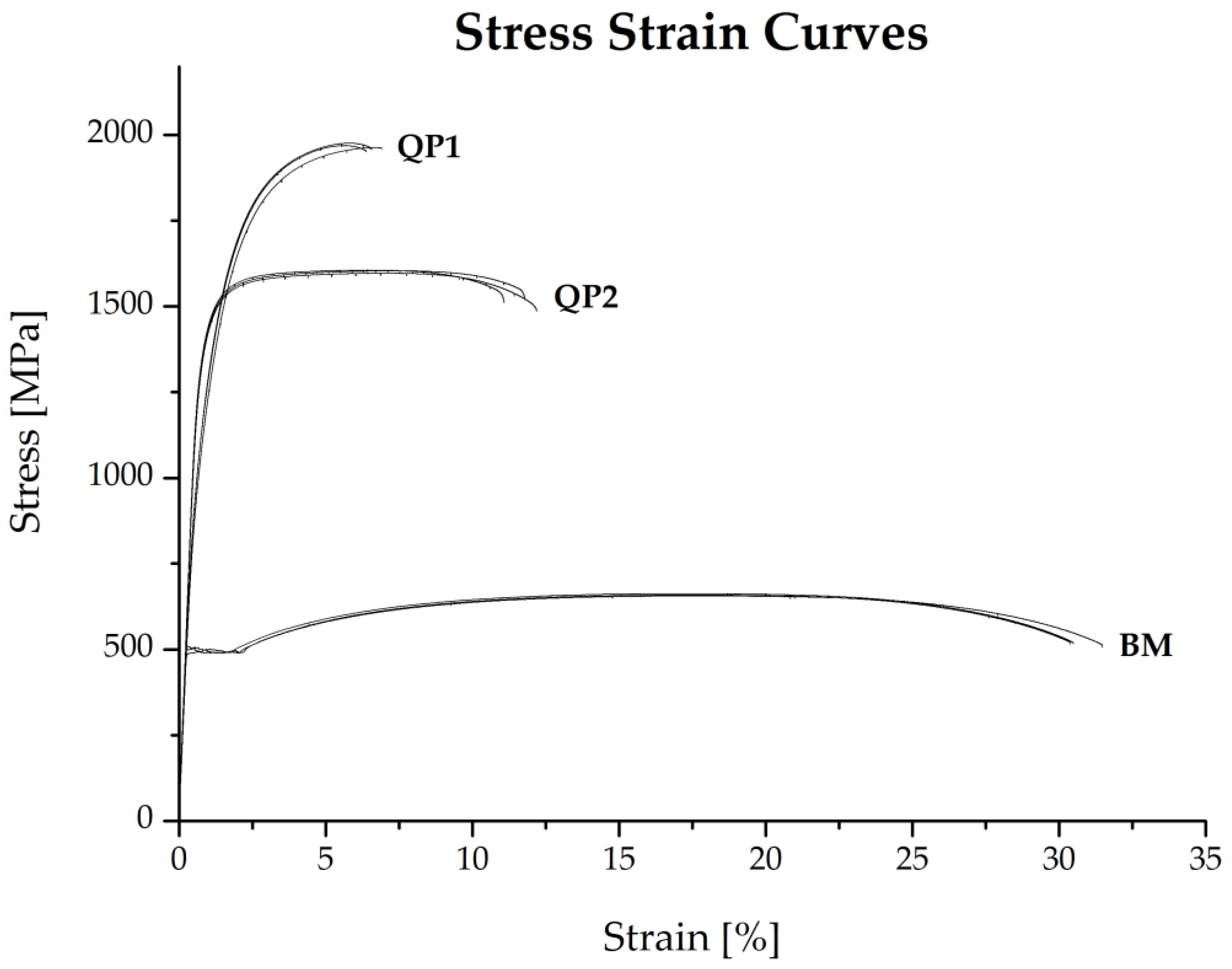
3.3. Monotonic Mechanical Testing

To investigate the effect of the varying amount of retained austenite in the microstructure under QP conditions on the resulting mechanical properties, tensile tests were carried out at first. Figure 6 depicts the stress–strain curves for the QP1 and QP2 as well as for the cold-rolled base material 42SiCr.
The diagram shows a good accordance for the three replicate samples of each condition. The cold-rolled base material reaches the lowest tensile strength of about 660 MPa but also the highest elongation at fracture of the three conditions of 30.5% according to expectations. In comparison to this, the QP1 obtained the highest tensile strengths of about 1970 MPa and a lower elongation maximum of 5.6%. These differences can be explained by the heat treatment with the resulting primary martensitic microstructure, containing 8.3% RA. This is in accordance with the work of Jenicek et al. [12]. The QP2 condition failed at an elongation maximum of 11% and reached a maximum tensile strength of about 1600 MPa, which corresponds to the findings of Calderon et al. [11]. In comparison to QP1, the lower average tensile strength as well as the higher ductility can be attributed to the higher amount of retained austenite in QP2, leading on one hand to more plastic deformation of the material as well as to a slower transformation of RA to martensite by the higher carbon content of the retained austenite of about 1.3%. In general, the achieved monotonic properties for QP1 and QP2 are in accordance with typical quenching and partitioning heat treatments, but depending on the process routes and the resulting amount of retained austenite, higher values are possible [10].

3.4. Cyclic Mechanical Testing

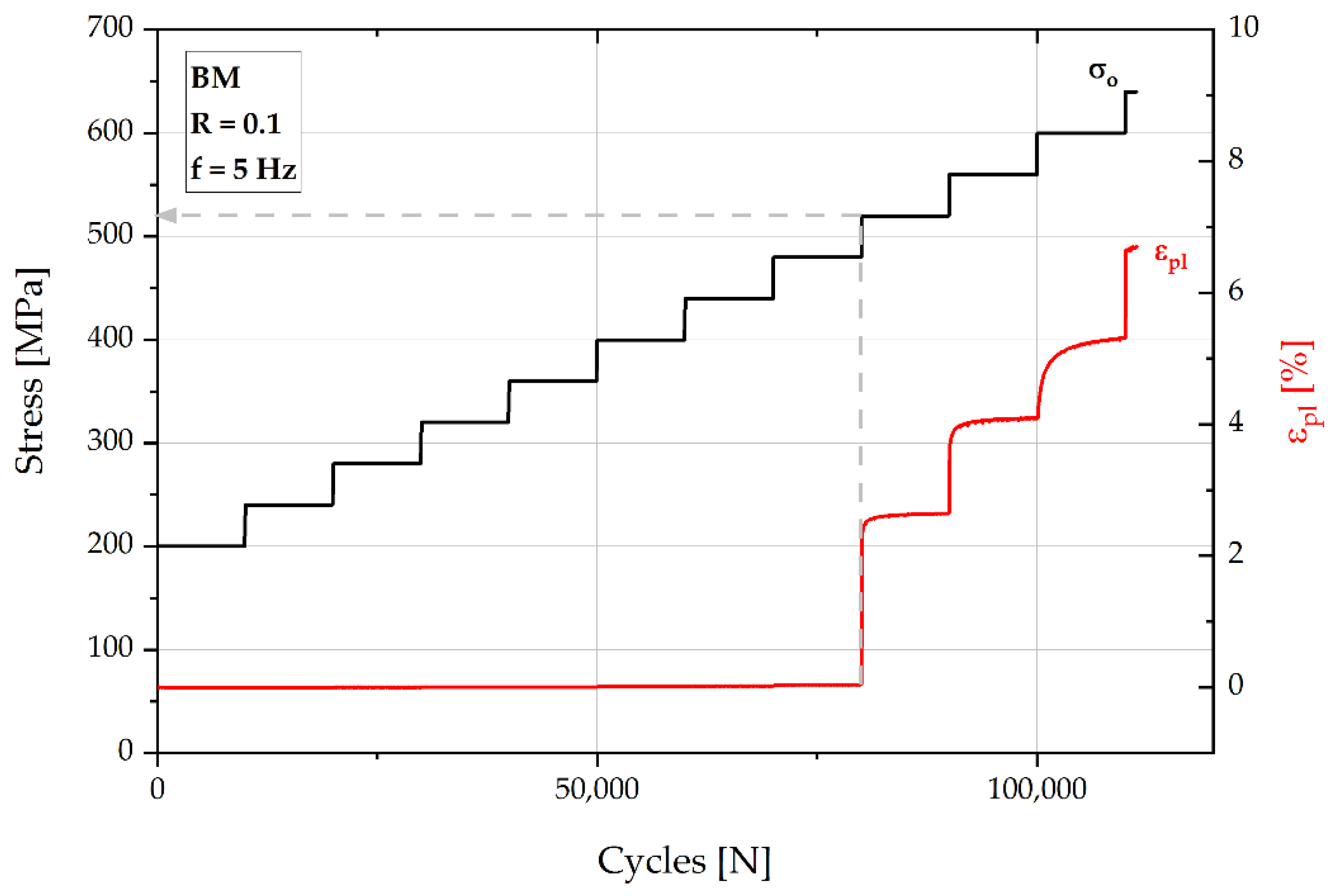
3.4.1. Load Increase Tests

Further investigations were carried out regarding the cyclic behavior of the different material conditions using load increase tests. Figure 7 shows a characteristic curve for the cold-rolled base material with an initial stress level of 200 MPa (40% of the yield strength).
The cold-rolled condition failed at a maximum stress of about 680 MPa after about 110,000 cycles.
Thereby, the stepwise load increase shows an explicit reaction for the plastic strain at the transition between step eight and nine after 80,000 cycles, which corresponds to a stress level of 520 MPa. This estimated fatigue strength is in the range of the yield strength of the material. In comparison, the cyclic behavior for load increase tests of a characteristic QP1 condition is depicted in Figure 8 (initial stress level of 450 MPa).
The maximum stress at failure is about 1290 MPa and occurs after about 216,000 cycles. The diagram shows also only a continuous rise of the plastic strain. This smooth transition from linear to exponential rise leads to the expectation that plastic deformation takes place nearly from the beginning of the test. The point of intersection for the applied tangents corresponds to about 100,000 cycles (transition from step ten to eleven) and a stress level of about 850 MPa, which is considerably higher than the estimated fatigue strength for the cold-rolled condition and agrees with the expectation. A characteristic QP2 condition is shown in Figure 9 (initial stress level of 550 MPa).
The maximum stress is about 1310 MPa at about 190,000 cycles. The plastic strain response is different compared to QP1. Its linear rise is almost zero until 120,000 cycles and a stress level of 1030 MPa before it starts to rise exponentially. Moreover, the plastic strain reaches lower maximum values of about 0.05% compared to about 0.12% for QP1. The estimated fatigue strength is also at a stress level of 1030 MPa, which is considerably higher than the value for QP1. Therefore, the maximum stress level at failure is nearly the same for both quenching and partitioning conditions with 1290 MPa (QP1) and 1310 MPa (QP2). The higher estimated stress level for the fatigue limit of QP2 can be attributed to the higher amount of retained austenite, which enables the material to stay in the elastic area for a longer time by transition-induced transformation of RA to martensite before more brittle material behavior starts to dominate. The enhanced stability of retained austenite for QP2 due to the higher carbon content in the RA contributes to a delayed phase transformation. The achieved estimated fatigue limits are in approximate accordance to the findings of Zhao [18].

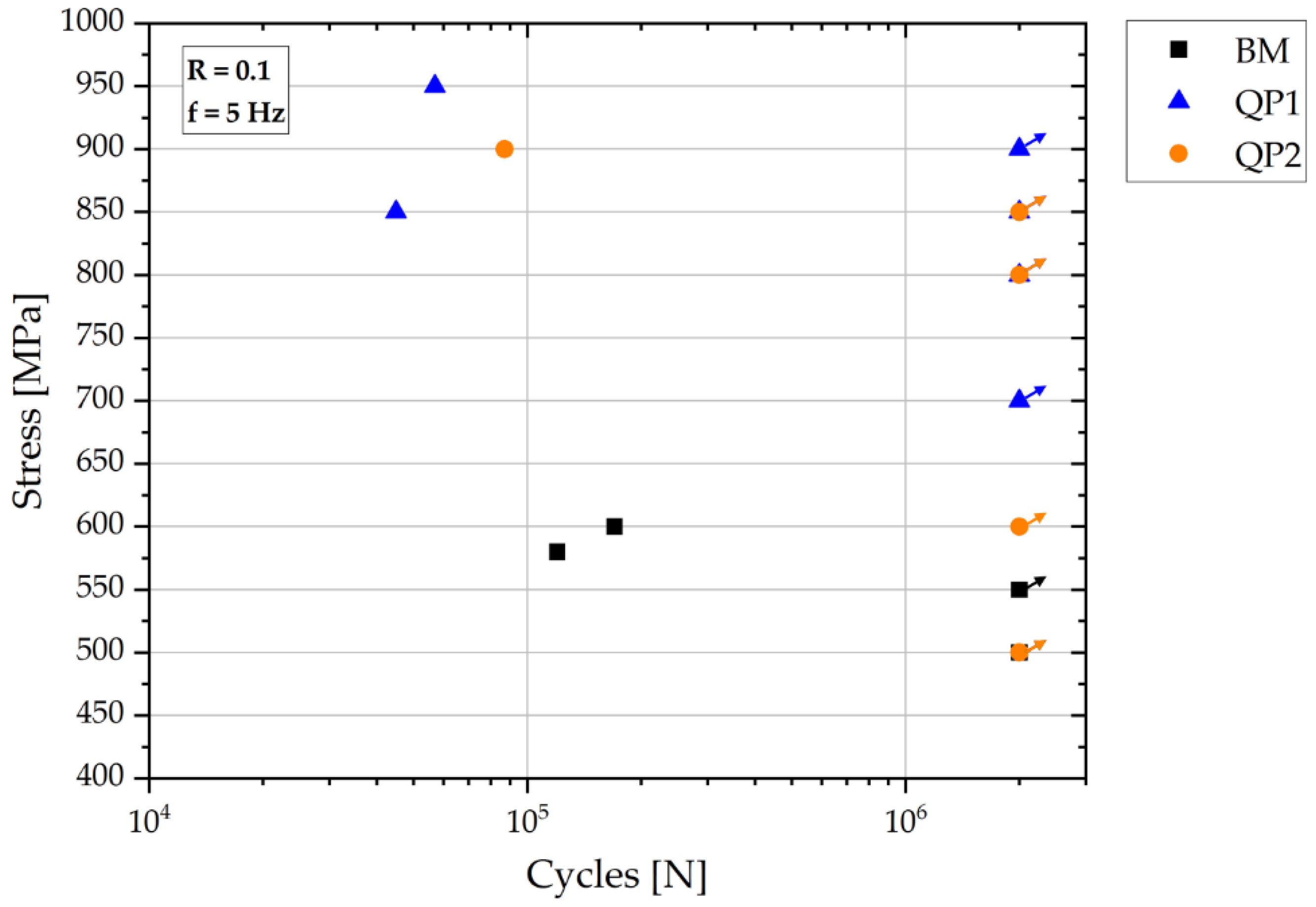
3.4.2. Constant Amplitude Tests

Subsequent constant amplitude tests in accordance to the staircase method with a small number of specimens were carried out to verify the received estimated fatigue strength from the CIT on the investigated conditions. Figure 10 shows the S-N diagram for all CAT.
The base material of the 42SiCr (square symbol) achieved a fatigue strength of 550 MPa and therewith the lowest value of the three conditions, as expected. This is in good accordance with the estimated fatigue strength of 520 MPa from the LIT. Regarding the number of cycles to failure for the stress amplitudes of 580 and 600 MPa, a strong decrease in the fatigue lifetime is visible. Compared to the base material, the QP1 (triangle symbol) condition reached a higher fatigue strength of 900 MPa and is also in good accordance with the estimated 850 MPa from the LIT. Even for this quenching and partitioning state, a more pronounced decrease in the fatigue lifetime for slightly elevated stress amplitudes like 950 MPa could be detected. The failed specimen for an amplitude of 850 MPa is attributed to the scattering of the QP process, which is also mentioned in the literature [19]. The condition QP2 (circle symbol) achieved only a value of 850 MPa for the fatigue strength, which is about 180 MPa lower than that estimated from the LIT and is in contrast to the findings of Zhao et al., mentioned before [18]. Regarding this, it seems that there is no significant difference in the fatigue strength of QP1 and QP2, whereas the tensile strength, which was higher for QP1, could be seen as a more dominant factor for the resistance against fatigue for the investigated quenching and partitioning conditions. Furthermore, this finding can be an effect of scattering also described in literature for the QP condition with the higher amount of retained austenite, which is QP2 in this work [11,14]. However, the achieved values of the fatigue strength of 900 MPa (QP1) and 850 MPa (QP2) are comparable to the findings in the literature of Cerny et al. [19].
In comparison to the microstructural investigations of the material in the initial state before cyclic loading, the fatigue fracture surfaces of the two QP conditions were also investigated after the constant amplitude tests. The fatigue fracture surface of a QP1 specimen is shown in Figure 11.
The picture shows the starting point of the fatigue crack (rectangular shape Figure 11a) at the surface of the specimen, which is characteristic for cyclic failure in the HCF regime. Furthermore, two different fracture areas are visible (Figure 11b). Fracture area I corresponds to the fatigue failure whereas fracture area II is attributed to the overload fracture. The fatigue fracture area shows a mainly transgranular failure with characteristic rest lines perpendicular to the crack growth (circle symbol). The overload fracture area is characterized by a ductile honeycomb structure, which is typical for this type of fracture. Furthermore, some globular carbides are present in area II (arrow symbols). Figure 12 shows the fatigue fracture surface of a QP2 specimen.
The starting point of the fatigue crack (rectangular shape Figure 12a) is again present at the surface of the specimen and also for the QP2 condition the same fracture areas are visible (Figure 12b) containing the similar transgranular failure behavior with rest lines in area I (circle symbol). The characteristic honeycombs are also present for the overload fracture (area II) and also here globular carbides can be found (arrow symbols). These fracture surfaces for the QP1 and QP2 condition are in good agreement with the findings of Melado and Calderon [11,14].
Further microstructural investigations were carried out regarding the resulting microstructure of selected runouts. The comparison between both conditions can be seen in Figure 13.
Figure 13a shows the martensitic microstructure with a globular carbide (circle symbol) of the QP1 specimen after achieving the fatigue limit. The lattice martensite around the carbide has a finer structure, which leads to the assumption that this martensite was formed by transition-induced plasticity due to the cyclic mechanical loading during the CAT. In comparison to that, the microstructure of the QP2 condition (Figure 13b) shows a different behavior, whereby the carbides are surrounded by retained austenite (dashed circle symbol). This can be explained with the higher amount of carbon for QP2 (1.31 wt% compared to 0.55 wt% for QP1) in the retained austenite leading to a stabilization of the RA. This finding could be used as an explanation for the improved fatigue strength of quenched and partitioned conditions with a higher amount of stabilized retained austenite mentioned in the literature and will be investigated in further research.

4. Conclusions

The present work investigated the influence of two different quenching and partitioning heat treatments on the microstructure and the monotonic as well as the cyclic mechanical properties compared to conventional cold-rolled 42SiCr steel. The main findings are as follows:
  • The QP1 process route with a lower quenching temperature of 200 °C as well as a lower partitioning temperature of 250 °C led to an expected higher amount of martensite and lower amount of retained austenite by 8.3% in the microstructure compared to the QP2 (quenching temperature 230 °C, partitioning temperature 380 °C), which reached 11.2% of retained austenite;
  • The detected differences in the microstructures considerably affected the resulting mechanical properties. QP1 achieved a higher ultimate tensile strength of about 1970 MPa in comparison to 1600 MPa for QP2, whereas the ductility of QP2 was more pronounced, reaching 11% (QP1 5.6%) and therefore showed a typical quenching and partitioning relation between ultimate tensile strength and elongation at fracture;
  • Load increase tests revealed a higher estimated fatigue strength of 1030 MPa for the QP2 condition compared to 850 MPa for QP1, which could be attributed also to the differing amount of retained austenite. Thereby the higher RA content of QP2 as well as its higher stability due to the higher carbon content could led to this enhancement;
  • Cyclic constant amplitude tests verified a good agreement of the estimated fatigue strength for the base material as well as the QP1 condition whereas the QP2 condition differed from this finding;
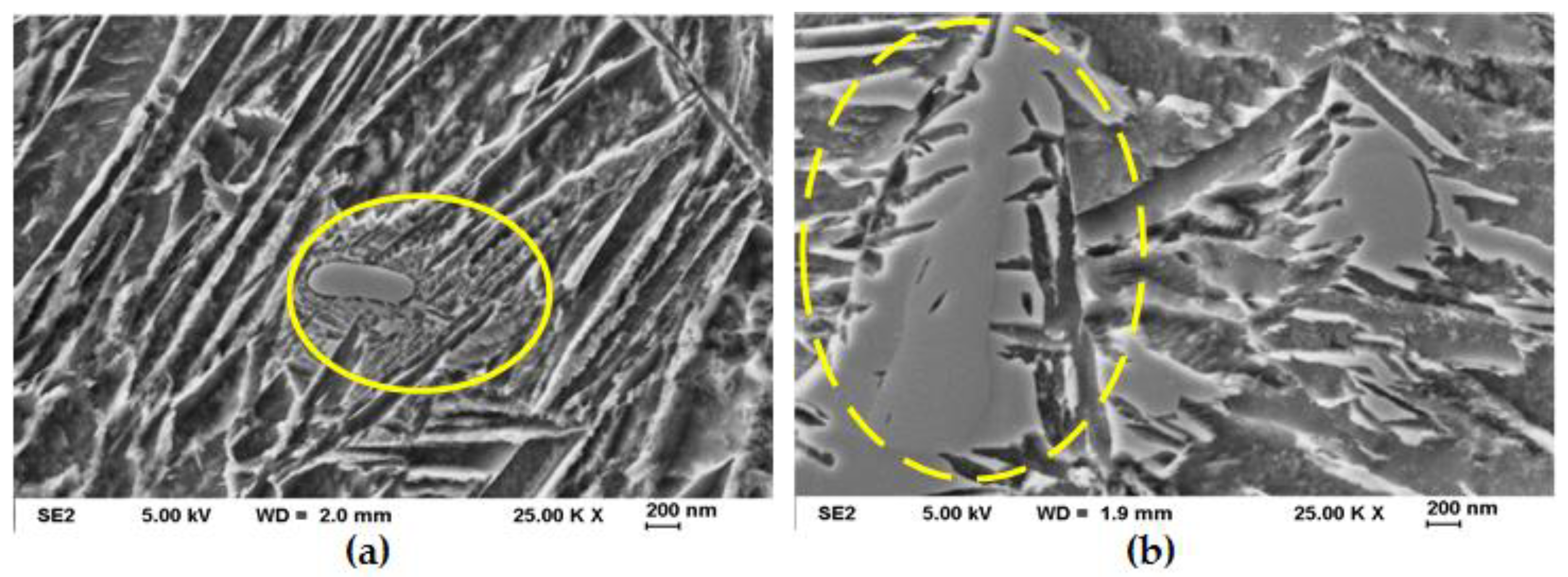
  • Both quenching and partitioning conditions showed a similar fracture behavior with the starting point at the surface of the specimens and containing two different fracture areas. The smaller fatigue fracture area was characterized by transgranular failure and rest lines whereas the larger overload fracture area showed a typical honeycomb structure; and
  • Regarding the microstructure of the runouts, the presence of retained austenite around globular carbides for QP2 in comparison to a finer martensitic lattice structure around the carbides for QP1 led to the assumption of a transition-induced plasticity during cyclic loading for QP1.

Author Contributions

Conceptualization, M.T. and G.W.; Methodology, M.T. and G.W.; Formal Analysis, M.T. and G.W.; Investigation, M.T.; Writing-Original Draft Preparation, M.T.; Writing-Review & Editing, M.T. and G.W. All authors have read and agreed to the published version of the manuscript.

Funding

The publication of this article was funded by Chemnitz University of Technology.

Acknowledgments

We thankfully acknowledge Harry Podlesak and Andreas Gester, for their support during the research work.

Conflicts of Interest

The authors declare no conflict of interest.

References

  1. Mughrabi, H. Specific features and mechanisms of fatigue in the ultrahigh-cycle regime. Int. J. Fatigue 2006, 28, 1501–1508. [Google Scholar] [CrossRef]
  2. Starke, P.; Walther, F.; Eifler, D. PHYBAL—A new method for lifetime prediction based on strain, temperature and electrical measurements. Int. J. Fatigue 2006, 28, 1028–1036. [Google Scholar] [CrossRef]
  3. Starke, P.; Walther, F.; Eifler, D. New fatigue life calculation method for quenched and tempered steel SAE 4140. Mater. Sci. Eng. A 2009, 523, 246–252. [Google Scholar] [CrossRef]
  4. Ebel-Wolf, B.H. Characterisation of the Cyclic Deformation Behaviour of the Magnesium Die-Cast Alloys MRI 153M and MRI 230D. Ph.D. Thesis, Technische Universität Kaiserslautern, Kaiserslautern, Germany, 2007. [Google Scholar]
  5. Koster, M.; Wagner, G.; Eifler, D. Cyclic deformation behavior of a medium carbon steel in the VHCF regime. Procedia Eng. 2010, 2, 2189–2197. [Google Scholar] [CrossRef] [Green Version]
  6. Speer, J.; Matlock, D.K.; De Cooman, B.C.; Schroth, J.G. Carbon partitioning into austenite after martensite transformation. Acta Mater. 2003, 51, 2611–2622. [Google Scholar] [CrossRef]
  7. Speer, J.G.; Matlock, D.K.; Wang, L.; Edmonds, D.V. Quenched and Partitioned Steels. In Comprehensive Materials Processing: Quenched and Partitioned Steels; Speer, J.G., Matlock, D.K., Wang, L., Edmonds, V.D., Eds.; Elsevier: Amsterdam, The Netherlands, 2014; pp. 217–225. ISBN 9780080965338. [Google Scholar]
  8. Toji, Y.; Miyamoto, G.; Raabe, D. Carbon partitioning during quenching and partitioning heat treatment accompanied by carbide precipitation. Acta Mater. 2015, 86, 137–147. [Google Scholar] [CrossRef]
  9. Clarke, A.J.; Speer, J.G.; Miller, M.K.; Hackenberg, R.E.; Edmonds, D.V.; Matlock, D.K.; Rizzo, F.C.; Clarke, K.D.; de Moor, E. Carbon partitioning to austenite from martensite or bainite during the quench and partition (Q&P) process: A critical assessment. Acta Mater. 2008, 56, 16–22. [Google Scholar] [CrossRef]
  10. Jirková, H.; Mašek, B.; Wagner, M.F.-X.; Langmajerová, D.; Kučerová, L.; Treml, R.; Kiener, D. Influence of metastable retained austenite on macro and micromechanical properties of steel processed by the Q&P process. J. Alloys Compd. 2014, 615, S163–S168. [Google Scholar] [CrossRef]
  11. Diego-Calderón, I.d.; Rodriguez-Calvillo, P.; Lara, A.; Molina-Aldareguia, J.M.; Petrov, R.H.; de Knijf, D.; Sabirov, I. Effect of microstructure on fatigue behavior of advanced high strength steels produced by quenching and partitioning and the role of retained austenite. Mater. Sci. Eng. A 2015, 641, 215–224. [Google Scholar] [CrossRef]
  12. Jenicek, S.; Vorel, I.; Kana, J.; Opatova, K.; Rubesova, K.; Kotesovec, V.; Masek, B. Evolution of microstructure and mechanical properties during Q&P processing of medium-carbon steels with different silicon levels. IOP Conf. Ser. Mater. Sci. Eng. 2017, 181, 12035. [Google Scholar] [CrossRef] [Green Version]
  13. Kucerova, L.; Jirkova, H.; Hauserova, D.; Masek, B. (Eds.) Analysis of 42SiCr Steel after Quenching and Partitioning by Laser Scanning Confocal Microscopy, 1st ed.; Tanger Ltd.: Ostrava, Czech Republic, 2010. [Google Scholar]
  14. Melado, A.C.; Nishikawa, A.S.; Goldenstein, H.; Giles, M.A.; Reed, P.A.S. Effect of microstructure on fatigue behaviour of advanced high strength ductile cast iron produced by quenching and partitioning process. Int. J. Fatigue 2017, 104, 397–407. [Google Scholar] [CrossRef] [Green Version]
  15. Timokhina, I.B.; Hodgson, P.D.; Pereloma, E.V. Effect of microstructure on the stability of retained austenite in transformation-induced-plasticity steels. Metall. Mater. Trans. A 2004, 35, 2331–2341. [Google Scholar] [CrossRef] [Green Version]
  16. Gao, G.; Zhang, B.; Cheng, C.; Zhao, P.; Zhang, H.; Bai, B. Very high cycle fatigue behaviors of bainite/martensite multiphase steel treated by quenching-partitioning-tempering process. Int. J. Fatigue 2016, 92, 203–210. [Google Scholar] [CrossRef]
  17. Xie, Z.; Zheng, Y.; Tian, Q.; Wang, A.; Chen, Y.; Mao, X.; Lu, Y.; Wang, X. Experimental investigation on fatigue failure characteristics of QP-16 type ball-eye under bending load. Eng. Fail. Anal. 2018, 89, 1–14. [Google Scholar] [CrossRef]
  18. Zhao, P.; Zhang, B.; Cheng, C.; Misra, R.D.K.; Gao, G.; Bai, B.; Weng, Y. The significance of ultrafine film-like retained austenite in governing very high cycle fatigue behavior in an ultrahigh-strength MN–SI–Cr–C steel. Mater. Sci. Eng. A 2015, 645, 116–121. [Google Scholar] [CrossRef]
  19. Černý, I.; Mikulová, D.; Sís, J.; Mašek, B.; Jirková, H.; Malina, J. Fatigue properties of a low alloy 42SiCr steel heat treated by quenching and partitioning process. Procedia Eng. 2011, 10, 3310–3315. [Google Scholar] [CrossRef] [Green Version]
  20. Scott, C.P.; Drillet, J. A study of the carbon distribution in retained austenite. Scr. Mater. 2007, 56, 489–492. [Google Scholar] [CrossRef]
  21. DIN Deutsches Institut für Normung e. V. Luft- und Raumfahrt—Prüfverfahren für Metallische Werkstoffe—Schwerlastwechselermüdung (HCF) im kraftgesteuerten Versuch, 2010–01; Beuth Verlag GmbH: Berlin, Germany, 2010; p. 3987. [Google Scholar]
  22. DIN Deutsches Institut für Normung e. V. Schwingfestigkeitsversuch—Durchführung und Auswertung von Zyklischen Versuchen mit Konstanter Lastamplitude für Metallische Werkstoffproben und Bauteile, 2016–12; Beuth Verlag GmbH: Berlin, Germany, 2016. [Google Scholar]
  23. Mehner, T.; Morgenstern, R.; Frint, P.; Scharf, I.; Wagner, M.F.-X.; Lampke, T. Corrosion characteristics of a quenching and partitioning steel determined by electrochemical impedance spectroscopy. IOP Conf. Ser. Mater. Sci. Eng. 2018, 373, 12003. [Google Scholar] [CrossRef]
Figure 1. Scheme of the QP heat treatment for the investigated QP1 and QP2 conditions.
Metals 11 01699 g001
Figure 2. Used geometry of the fatigue specimen following DIN EN 3987 in mm.
Metals 11 01699 g002
Figure 3. Comparison of light microscopic images of (a) base material, (b) QP1 and (c) QP2.
Metals 11 01699 g003
Figure 4. (a) Scanning electron microscopic image of QP1; (b) detail QP1.
Metals 11 01699 g004
Figure 5. (a) Scanning electron microscopic image of QP2; (b) detail QP2.
Metals 11 01699 g005
Figure 6. Stress–strain curves for the cold-rolled base material and the QP1 and QP2 condition.
Metals 11 01699 g006
Figure 7. Load Increase Test for the cold-rolled base material.
Metals 11 01699 g007
Figure 8. Load Increase Test for the QP1 condition.
Metals 11 01699 g008
Figure 9. Load Increase Test for the QP2 condition.
Metals 11 01699 g009
Figure 10. S-N diagram of the investigated constant amplitude tests for BM, QP1, QP2.
Metals 11 01699 g010
Figure 11. (a) Fatigue fracture surface of a QP1 specimen with (b) different fracture areas.
Metals 11 01699 g011
Figure 12. (a) Fatigue fracture surface of a QP2 specimen with (b) different fracture areas.
Metals 11 01699 g012
Figure 13. Microstructural comparison of runouts of (a) QP1 and (b) QP2.
Metals 11 01699 g013
Table 1. Chemical composition of the studied 42SiCr steel.
ElementCSiCrMnPSNiMoNb
Amount [wt%]0.381.921.390.660.0110.00510.0610.0380.048
Table 2. Mass fraction and lattice parameters of the phases of the QP1 and QP2 conditions.
Microstructural PropertiesQP1QP2
Martensite
Mass fraction [wt%]91.788.8
Austenite
Mass fraction [wt%]8.311.2
Lattice parameter a [nm]0.35910.3616
Carbon content wC [wt%]0.551.31
Publisher’s Note: MDPI stays neutral with regard to jurisdictional claims in published maps and institutional affiliations.

