Review

Microstructure Design and Its Effect on Mechanical Properties in Gamma Titanium Aluminides

1
Department of Materials Science and Engineering, Guangdong Technion Israel Institute of Technology, Shantou 515063, China
2
Department of Materials Science and Engineering, Technion Israel Institute of Technology, Haifa 32000, Israel
3
Guangdong Technion Israel Institute of Technology, Shantou 515063, China
*
Author to whom correspondence should be addressed.
First and second authors (Xuqi Liu and Qia Lin) equally contributed to the work.
Metals 2021, 11(10), 1644; https://doi.org/10.3390/met11101644
Submission received: 1 September 2021 / Revised: 11 October 2021 / Accepted: 13 October 2021 / Published: 16 October 2021
(This article belongs to the Special Issue Microstructure and Properties of High Temperature Intermetallic)

Abstract

:
Intermetallic gamma titanium aluminides display attractive engineering properties at high temperatures of up to 750 °C. To date, they have been used in low-pressure turbine blades and turbocharger rotors in advanced aircraft and automotive engines. This review summarizes the fundamental information of the Ti–Al system. After providing the development of γ   TiAl alloys, typical phases, microstructures and their characteristics in TiAl alloys, the paper focuses on the effects of alloying elements on the phase boundary shifting, stabilizing effects and strengthening mechanism. The relationships between chemical additions, microstructure evolution and mechanical properties of the alloy are discussed. In parallel, the processing technologies and the common heat treatment methods are described in detail, both of which are applied to optimize the mechanical properties via adjusting microstructures. On this basis, the effects from chemical composition, processing technologies and heat treatments on microstructure, which controls the mechanical properties, can be obtained. It has a certain guiding significance for tailoring the microstructures to gain desired mechanical properties.

1. Introduction

Titanium aluminides have been studied for at least 40 years, and are widely recognized lightweight high-temperature materials. Of these, interest has primarily focused on the gamma titanium aluminides ( γ TiAl alloys), which are mainly composed of the γ -TiAl phase and are considered as advanced aero-engine materials. Compared with conventional materials in this field, such as nickel-based alloys, intermetallic γ TiAl alloys possess numerous attractive properties, such as low density (3.9–4.2 g/cm3), high specific strength and good creep properties up to high temperatures. They also exhibit better oxidation resistance than conventional Ti alloys. Four generations of γ TiAl alloys have been developed. Kim and Clemens et al. [1,2] summarized the first three generations based on their chemical composition and microstructures. First generation alloys are Ti–48Al–(1–3)X (at. %), where X = V, Mn, Cr and W. Their ductility at room temperature (RT) vary with Al content, exhibiting the maximum plasticity of Ti–48Al based alloy [1]. Second generation alloys can be summarized as Ti–(45–48)Al–(1–3)X–(2–5)Y–(<1)Z (at. %), where X = V, Cr and Mn; Y = Nb, Ta and W, Mo; Z = Si, B and C. These kinds of alloys exhibit relatively good tensile properties and fracture toughness; however, their creep resistance seems to limit the service temperature under 700 °C [2]. Third generation alloys can be written as Ti–(42–48)Al–(0–10)X–(0–3)Y–(0–1)Z–(0–0.5RE) (at. %), where X = Cr, Mn, Nb and Ta; Y = Mo, W, Hf and Zr; Z = Si, B and C; RE denotes rare earth elements. These alloys are designed to have a balance of mechanical properties. Recently, fourth generation γ TiAl alloys are being developed which aim to improve the working temperature to more than 750 °C. There is still not a specific definition of the composition range. Several compositions have attracted interest and are under development, including the TNM+ (Ti–43.5Al–4Nb–1Mo–0.3C–0.3Si–0.1B at. %) alloys and BMBF alloys ( γ TiAl alloys for additive manufacturing by electron beam melting, funded by the German Federal Ministry of Education and Research) [3,4,5]. Different generations of γ TiAl alloys have been applied in automotive and aircraft engines for many years during the development process. The first commercial aircraft engine using the so-called 4822TiAl (Ti–48Al–2Cr–2Nb at. %) alloy is GEnxTM engine, announced by General Electric in 2006 [6,7]. Later on, TNM alloy (Ti–43.5Al–4Nb–1Mo–0.1B at. %) is also used to manufacture the low pressure turbine for PW 1100TGTM engine [8].
The understanding of relationships among microstructures, processing technologies and mechanical behaviors could help to design these advanced alloys with superior and balanced properties. Therefore, the main objective of this article is to analyze and summarize research on the factors (alloying elements, processing technologies and heat treatments) that can effect alloy microstructure, integrating the effects between microstructures and mechanical properties. The review is organized as follows: Firstly, an overview of the Ti–Al system sums up the basic crystallographic data as well as Al content in common phases, and introduces four kinds of typical microstructures. Secondly, alloying elements of γ TiAl alloys are divided into two groups, and their effects on the microstructural stability and mechanical properties are discussed. Thirdly, the ways γ TiAl alloys are manufactured by different processing routes and heat treatments are illustrated. Finally, creep resistance, ductility, strength and hardness of different microstructures of the alloys are discussed, which are then followed by a summary and outlook to future research.

2. Typical Phases and Microstructures in γ TiAl Alloys

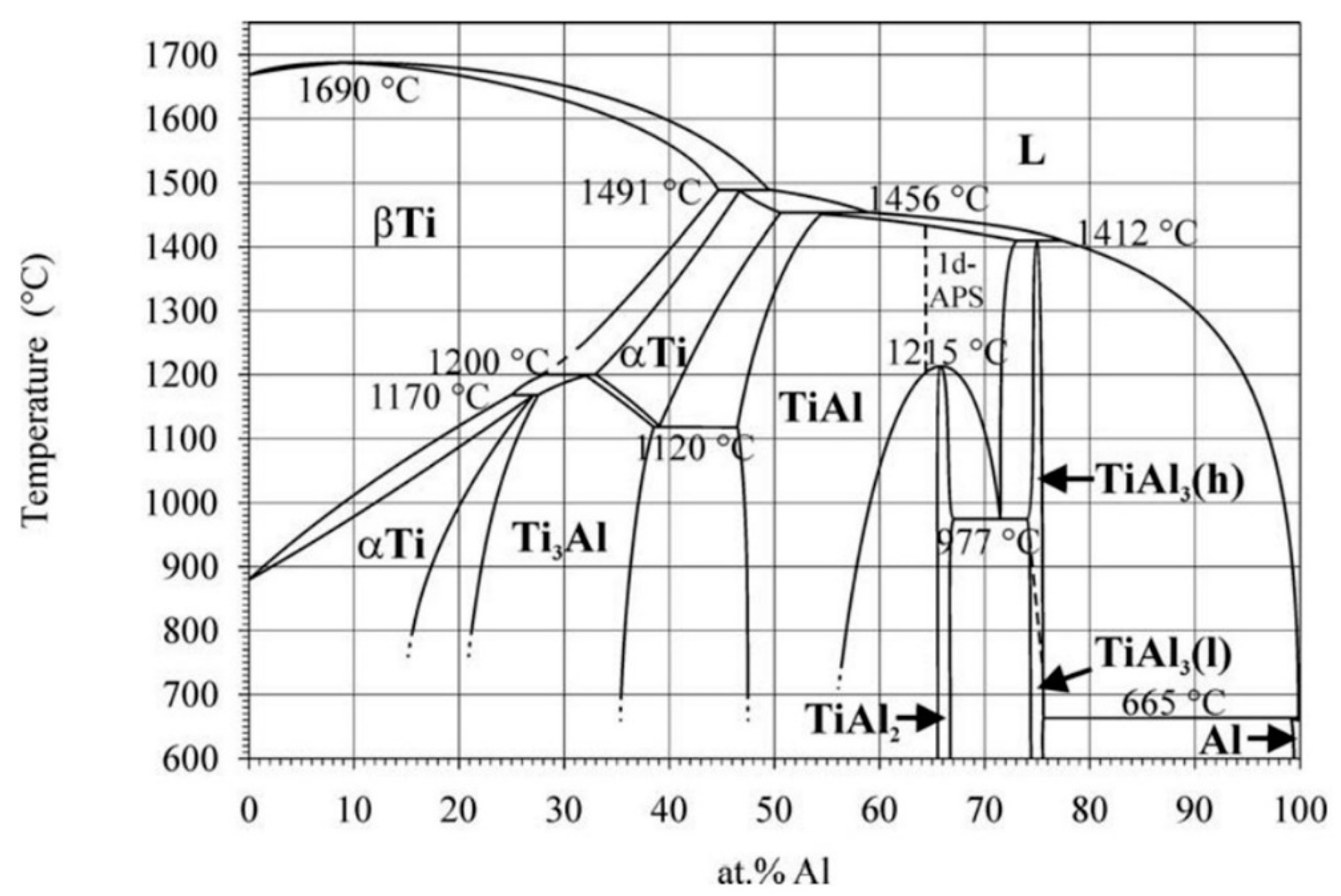
2.1. Phases in the Ti–Al System

According to the Ti–Al binary phase diagram shown in Figure 1 [9], there are several typical phases of alloys with 42 to 48 at. % Al, which are β , β 0 , α , α 2 and γ phase. Table 1 summarizes the crystallographic data (Pearson symbol, space group, structure and lattice parameters) of relevant phases present in the alloys [10,11,12,13]. Different phase transformations occur following a specific orientation relationship at a certain temperature range. The β - T i phase, the Al content of which can reach up to 44 at. %, starts to solidify at the temperature of liquidus line (the lowest one is 1500 °C). At a lower temperatures in the range of 1200 to 1400 °C, the disordered β phase with body centered cubic (BCC) A2 structure will transform into the ordered β 0 phase with B2 structure. It should be noted that the ordered to disordered transition temperatures show a large inconsistency between the calculated and experimental results, i.e., the transition temperature is far below the value predicted by ThermoCalc [14,15]. When the temperature continues decreasing to α -transus temperature ( T α ), the β phase will transform into the α phase by following Burger orientation relationship { 110 } β ( 0001 ) α and < 111 > β   < 11 2 ¯ 0 > α [16]. Since the BCC β phase has six slipping planes and two slipping directions, resulting in 12 variants, then α phase can form with up to 12 orientation variants.
Next, an α - T i phase is a disordered hexagonal A3 structure. Ordered α 2 - T i 3 A l phases can form through a disordered to ordered transition. An α 2 - T i 3 A l phase is a hexagonal D019 structure with Al content between 21 and 38 at. %. The γ - T i A l phase is another critical phase with centered tetragonal L10 structure, which contains 47 to 66 at. % Al. When the temperature decreases to eutectoid temperature, γ lamellae can form in α grains by following the Blackburn-orientation relationship ( 0001 ) α 2     { 111 } γ and < 11 2 ¯ 0 > α 2 < 1 1 ¯ 0 ] γ [17].
Moreover, in high Nb containing TiAl alloys, which have 4–10 at. % Nb content, the β / β 0 phase can decompose into an ω 0 or ω phase [10,11,12,13]. The ω 0 - T i 4 A l 3 N b phase has an ordered B82 structure, which has an orientation relationship with the β 0 phase, i.e., { 111 } β 0 { 0001 } ω 0 and < 1 1 ¯ 0 > β 0   < 11 2 ¯ 0 > ω 0 [11]. Additionally, an ω - T i 4 A l 3 N b phase is a metastable intermediate phase during the complete transformation of β 0 ω ω 0 . The information of ω -related phases are summarized in Table 1 and are referred in Refs. [10,11,12,13].

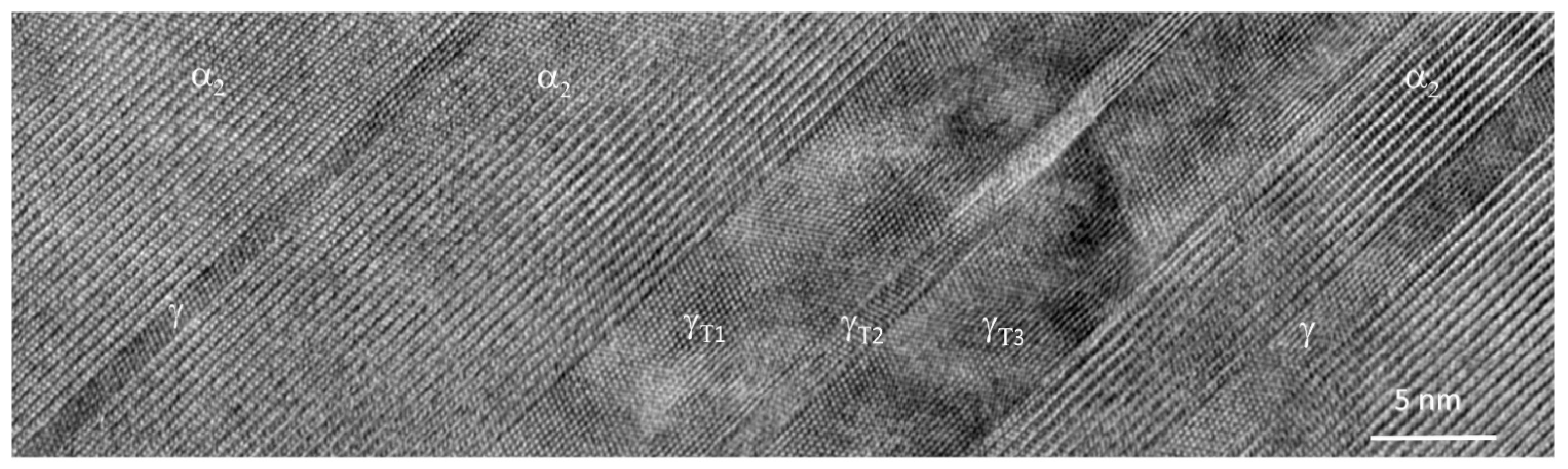
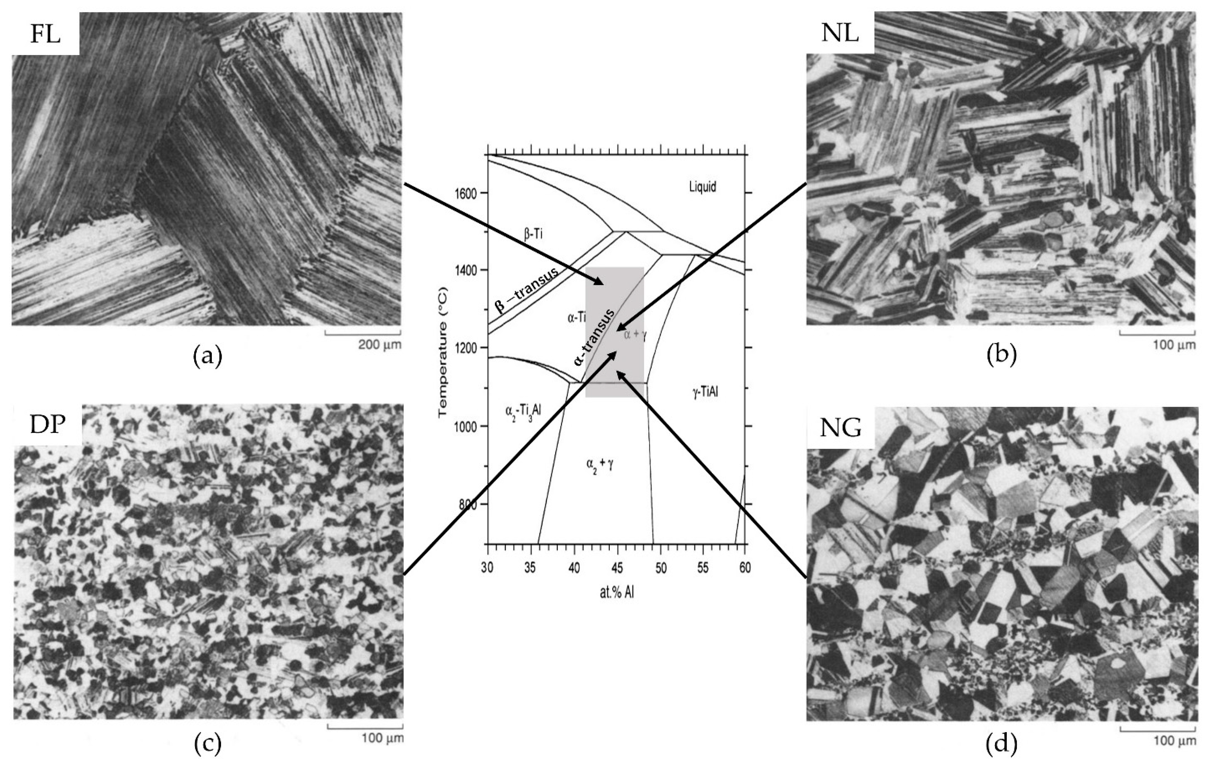
2.2. Typical Microstructures and Their Characteristics

Single phase TiAl alloys, which consist only of a γ phase, attracted attention initially because of their excellent resistance to environment corrosion [18]. However, these alloys had poor RT ductility as well as poor fracture toughness, so two-phase TiAl alloys have received more attention in the literature [19,20]. Two-phase TiAl alloys consist of 𝛾-𝑇𝑖𝐴𝑙 phase and α 2 - T i 3 A l phase with Al content ranging from 37 to 49 at. % [21]. These alloys have a good combination of high temperature tensile strength, creep resistance and RT ductility, which are strongly related to their element additions, grain sizes and microstructures [22]. In order to improve the hot-workability of the alloys, multi-phase TiAl alloys containing ( α 2 + γ + β ) phases are introduced, for instance, TNM alloys [15]. When large amounts of β stabilizers, such as Nb, are added into the system, the β / β 0 phase is remained at RT, which forms multi-phase TiAl alloys. Two-phase TiAl alloys and multi-phase TiAl alloys are classified as γ TiAl alloys in this article.
In general, γ TiAl alloys have four typical microstructures, which are fully lamellar (FL), nearly lamellar (NL), duplex (DP) and near γ (NG), as shown in Figure 2 [18]. These microstructures can be obtained by adjusting composition and heat treatments.
A FL microstructure is composed of γ - T i A l laths and α 2 - T i 3 A l laths, which demonstrates a plate-like morphology [19]. The Blackburn-orientation relationships between γ and α 2 lamellae are shown above. This microstructure can be obtained by heating the alloy to the single α phase field above α -transus temperature T α and then cooling it down (see Figure 2). It is usually characterized with coarse colonies in hundreds of microns [21]. However, colony size can also be refined down to tens of microns by adding some elements, such as B [23].
When the alloy is heated in the two phases ( α + γ ) region (see Figure 2) and then is cooled down, a DP microstructure forms, consisting of lamellar colonies and equiaxed γ grains [24,25]. The temperature in the ( α + γ ) phase region is where the γ / α volume ratio is close to 1. Then, while cooling, the α grains will transform into γ / α 2 lamellae colonies while γ grains remain unchanged. As a result, a typical DP microstructure is generally composed of 50% γ grains and 50% γ / α 2 lamellar colonies [26]. The typical grain and colony sizes of the mixture are in dozens of microns [11,21].
When the alloy is heated at temperatures higher than where the DP microstructure forms (see Figure 2), the α grains are coarsened and a NL structure with equiaxed γ grains (NLγ) shows up. The grain size of the equiaxed γ grains is in the range of a few hundred microns [21]. Another microstructure is NL structure with β grains (NLβ), where no γ grains are present. They could be obtained by heating the alloy to the temperature of ( α + β ) region and then cooling it down [27].
Additionally, the NG microstructures are obtained by heating the alloy to a relatively low temperature that is close to eutectoid temperature T e u (see Figure 2), and then cooling it down. This is because below the temperature where the duplex structures form, coarsening of γ grains becomes predominant. The average grain sizes for this microstructure usually range between tens of microns [21].
Of these microstructures, lamellar microstructures and duplex microstructures have exhibited attractive mechanical properties, which are satisfied with the engineering purposes and commercial application. Therefore, the following paragraphs highlight the characteristics of lamellar microstructure and duplex microstructure.
The lamellar microstructure exhibits a superior combination of strength, creep, fracture toughness but poor ductility and machinability in γ TiAl alloys. The properties of the lamellar structure were investigated by using polysynthetic twinned crystal (PST). The lamellar structure is extremely anisotropic, the orientation of which would strongly affect the tensile property. When the angle between tensile axial and lamellar orientation is 0 degree, a good balance of strength and ductility is obtained [28]. The tensile yield strength and macro-hardness are correlated with the average interface spacing. Due to the size effect [29], when both α 2 and γ lath are in nano-scale region (see Figure 3), they approach their theoretical hardness. In this case, the effect of volume fraction to hardness should be considered [30].
A DP microstructure exhibits higher ductility but relatively lower fracture toughness than a FL microstructure. The elongation of the as-cast DP microstructure could reach 2% at RT and further increased after hot work and heat treatment [19,32]. The crack usually forms by cleavage through γ grains leading to the low fracture toughness, although the lamellar could block the crack propagation [26]. Another factor that affects the ductility in DP microstructure is the existence of ordered β 0 phase at RT. The hard and brittle β 0 phase will decrease the ductility of the alloys [26].

3. Effects of Alloying Elements on Microstructures

The addition of different alloying elements plays a vital role in developing γ TiAl alloys. By adding transition elements, such as Nb, Mo, Ta, W, Mn, V and Cr, and light elements, such as B, C and Si, γ TiAl alloys can achieve good microstructural stability and mechanical properties at their service temperature. In second generation alloys, the addition of alloying elements (Mn, V, Cr, Nb, Mo, Ta and W) in small amounts can increase their ductility and fracture toughness. Then, in the third generation, a significant addition of alloying elements, usually 4–10 at. %, is crucial in improving alloy properties, especially hot workability and creep resistance at high temperature by affecting the phase formation. Among them, the alloys with 4–10 at. % Nb content, called high Nb containing TiAl alloys, have received much attention for the last two decades, such as TNB alloys (Ti–45Al–(8–9)Nb–(W, B, Y) at. %) [33] and TNM alloys (4 at. % Nb) [2]. The addition of Nb can stabilize the high temperature β phase. Additionally, light element additions, B, C and Si, can enhance the strength and creep resistance at high temperature by forming solid solutions or precipitations. However, a real difficulty with multi-component composition is shifting the phase boundaries, which affects the temperatures of heat treatment to obtain specific microstructures. Therefore, it is of great importance to investigate the relationship between them.

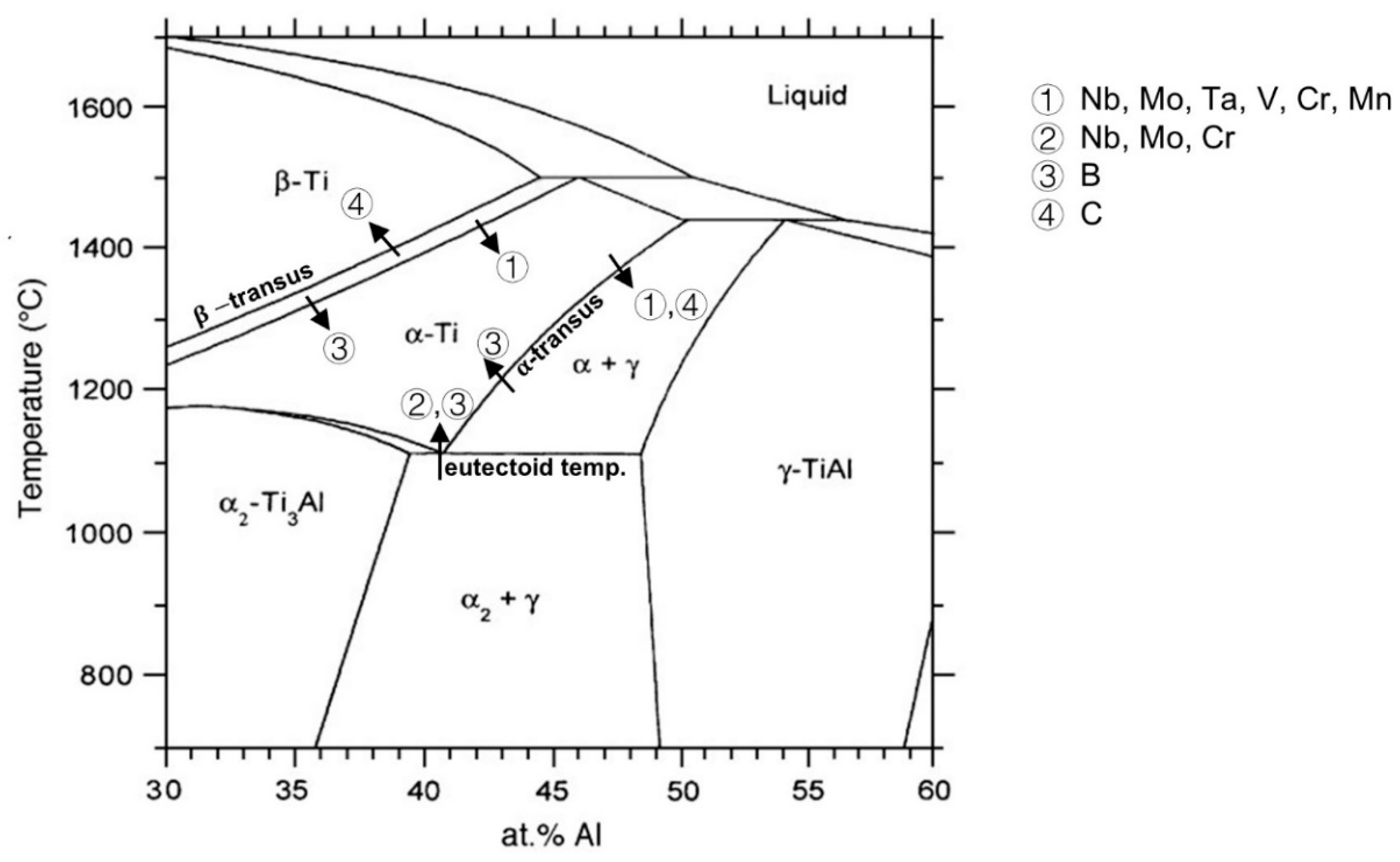
3.1. Nb, Mo, Ta, W, Mn, V and Cr

The addition of transition elements into the Ti–Al system mainly contains Nb, Mo, Ta, W, Mn, V and Cr. These elements, also called β stabilizers, tend to partition into the β phase. Due to the additions, the α α + β transition temperature decreases, and the β phase region in the phase diagram is expanded, which means that the β phase has a higher probability to be present thermodynamically compared to the alloy without the additions. Figure 4 summarizes the effects of different elements concerning the shifting of phase boundaries [15,34,35,36,37,38]. As indicated by arrow ①, the additions of Nb, Mo, Ta, V, Cr (larger than 2 at. %) and Mn lead to the decrease in both the α α + β transition temperature and the α -transus temperature. Nb, Mo and Cr additions increase the eutectoid temperature slightly as indicated by arrow ② [38]. The other elements in Figure 4 will be explained in Section 3.2. Kainuma et al. [35] reported on the phase equilibria relationship for different alloying elements in the Ti–Al–X system and found that Nb, Mo, Ta, W, Cr and V tend to stabilize the β phase rather than the α , α 2 or γ phases. They also found that Mo, V, Cr, Ta and W always concentrate on the α or α 2 phase instead of the γ phase when regarding α / γ and α 2 / γ phase equilibria. The β -forming equivalency was estimated by Kim et al. [7] based on Ti–44Al–xX alloys showing that
Nb = Cr/3 = Mn/2 = V/2 = Mo/6 = W/8
From the equivalency formula above, W is the strongest β stabilizer and Nb is the weakest β stabilizer.
In terms of the β phase, on the one hand, the 12 independent slipping systems in the BCC lattice make the β phase have excellent ductility at elevated temperature [39]. On the other hand, the metastable β phase would decompose into α 2 and γ grains which accommodate stress concentration [40]. As a result, with the additions of β stabilizers, hot workability of γ TiAl alloys, such as rolling and forging, is improved by the presence of the disordered β phase. The processing temperature of the alloys with β stabilizers can also be reduced due to the shifting of phase boundary of α α + β transition, so that the industry can save the cost.
Although the β phase plays a vital role in thermo-mechanical properties for the alloys, it shows a hard and brittle ordered β 0 phase at service temperature (T < 750 °C) [41]. The β 0 phase also embrittles the alloy, thus decreasing the ductility at RT. Thus, the β 0 phase with low deformability should be eliminated through subsequent heat treatments. Clemens et al. [2] have developed a two-step heat treatment for TNM alloys. After the heat treatments, the alloy contains a small volume fraction of globular β 0 phase. Qiang et al. [42] have proposed a multi-step heat treatment for high Nb containing TiAl alloys. After the first two step heat treatment, the β -segregation is removed effectively. Such complex heat treatments are related to the high microstructural stability and slow diffusion of alloying elements Nb and Mo [26,42]. Cui et al. [26] reported that Mn and Cr have high diffusivity and are beneficial to the microstructural evolution, especially for the elimination of β 0 phase in Ti–43Al–2Cr–2Mn–0.2Y alloy.
Additionally, the β phase tends to decompose to a lower symmetry hexagonal ω 0 or ω phase in high Nb containing TiAl alloys, which is highly brittle and harmful to the ductility of the alloy. In Ti–40Al–10Nb alloy, the β phase transforms into an ω 0 phase below 900 °C [10]. In TNM alloy, it is found that Nb is a strong stabilizing element of the ω 0 phase [43]. Li et al. [44] have calculated the phase stability of β ,   β 0 ,   ω ,   ω 0 with different β stabilizing elements (V, Nb, Ta, Cr, Mo, W and Mn) by using the first principle method, so as to offer information to improve the mechanical properties by inhibiting the harmful ω -related phases. They demonstrated that the phase stability sequence is β < β 0 < ω 0 < ω for T i 4 A l 3 N b and T i 4 A l 3 T a , β < ω 0 < β 0 < ω for T i 4 A l 3 V , T i 4 A l 3 M o and T i 4 A l 3 W , and β < ω 0 < ω < β 0 for T i 4 A l 3 C r and T i 4 A l 3 M n . Stark et al. [11] have concluded that for high Nb containing alloys, the higher the Nb content and the more ω 0 / B 8 2 phase that is formed [10]. On the contrary, the addition of Mo would hinder the growth of ω 0 precipitates by stabilizing the β 0 phase leading to no tendency to transform into other phases at a temperature between 700 to 1150 °C [11,45].

3.2. B, C and Si

Generally, there are three kinds of light element additions: B, C and Si in γ TiAl alloys. Different kinds of solid solutions and precipitates are formed after adding these elements. Moreover, these light element additions affect phase boundaries as shown in Figure 4. B acts as β stabilizer. As indicated by arrow ③ in Figure 4, the addition of B lead to a slight increase in the eutectoid and α -transus temperatures and to a slight decrease in the α α + β transition temperature [37]. C is an α stabilizer. The minor addition with it increases the β -transus temperature but decreases the α -transus temperature as indicated by arrow ④, expanding the α phase region. The effect of Si on the shifting of phase boundary is seldom found.
The B element is widely added into γ TiAl alloys because less than 1 at. % of B addition effectively refines the microstructures [37,46]. This element can be added through various kinds of powders: B [47], titanium borides [47], aluminum borides [48] and even tantalum borides [49]. The solubility of B in α phase and γ phase is very limited which is 0.011 ± 0.006 at. % and < 0.003 at. %, respectively [50]. Therefore, B is usually present as borides in γ TiAl alloys. The common types of borides are T i B (B27), T i B (Bf), T i B 2 (C32) and T i 3 B 4 (D7b), which are found in different Ti–Al matrix compositions [49].
The refinement mechanism of B addition is related to when borides form during the solidification process. During β solidification, borides that form before β - α solid-state transformation could act as a nucleation site. Randomly orientated α grains grow on it and the grains are refined [37,51]. Similarly, in peritectic solidified alloys, the peritectic α phase also nucleate on borides in the interdendritic area during the L + β α peritectic reaction [49]. For borides precipitating at the end of the peritectic reaction, they have no time and space to grow. Those borides do not contribute to the growth of α phase [49]. It is worth pointing out that the addition of B is detrimental to the alignment of lamellar microstructure as the α phase grows on borides following a different orientation relationship rather than the Burger orientation relationship. Therefore, B is seldom added into directionally solidified alloys that target the alignment of lamellar orientation [52]. The critical B concentration is usually 0.5–0.8 at. % for peritectic alloys, but lower for β solidified alloys (~0.1 at. %) [53]. The refinement effect is significant up to the critical concentration, which reduces the colonies size from hundreds of microns to around dozens of microns. If the concentration is higher than the critical concentration, the grain size would not be reduced obviously [54].
The addition of C and Si can strengthen γ TiAl alloys by both solid solution and precipitation strengthening mechanisms [55]. To introduce C into the alloy, various powders can be used, such as C, T i C or B 4 C . [56,57], while Si powder is the most commonly used to introduce Si [58,59]. The strengthening mechanisms depend on the solubilities of C and Si in different phases.
The solubility of C is high in the α 2 phase but is low in γ and β 0 phases. The α 2 phase has the highest carbon solubility (~1.5 at. %) due to the T i 6 octahedral sites. With the addition of Nb, the solubility of C in the γ phase increases several times to around 0.25 at. %. It is because Nb occupies Ti site and creates Ti antisite defects in the γ phase [60]. The β 0 phase has almost no solubility of C. Within the C solubility limit, there is no carbide after processing [61]. After a long time annealing or creep test, p T i 3 A l C carbide would nucleate at the α 2 / γ interface and grow into γ -lamella [62]. The perovskite carbide can effectively pin the perfect and twinning partial dislocation, but the C solid solution can only act as weak obstacles which can be overcome by the aid of thermal activation [61,63]. Therefore, the strengthening effect is more significant in precipitated carbide than in C solid solution [63].
Si tends to sit on Al sites in α and γ phases because the energy required to form silicide through the incorporation of Si follows the sequence E f ω 0 < E f α 2 < E f γ < E f β 0 . The energy sequence demonstrates that the Si located in the ω 0 phase lattice site is energetically most favorable and followed by α 2 (solubility around 0.4–0.5 at. % Si) and γ (solubility around 0.2 at. % of Si) phase [64]. The location of the silicides depends on the Si concentration and the alloying composition. Noda et al. [65] have observed silicides at α 2 / γ interfaces in Ti–48Al–1.5Cr system. However, in TNM+ alloys, silicide tends to appear in the interior region of β 0 phase. No silicide is observed in the lamellar interface due to the large and stable α 2 phase fraction [64].
Both the addition of C and Si show a high potential to extend the working range of γ TiAl alloys. It is because C addition could improve the high temperature strength and creep resistance, and the addition of Si can enhance the oxidation resistance, corrosion resistance and creep resistance [56,66]. Moreover, the apparent activation energy of γ TiAl alloys is increased by alloying C and Si, which leads to a decrease of the minimum creep rate [5].

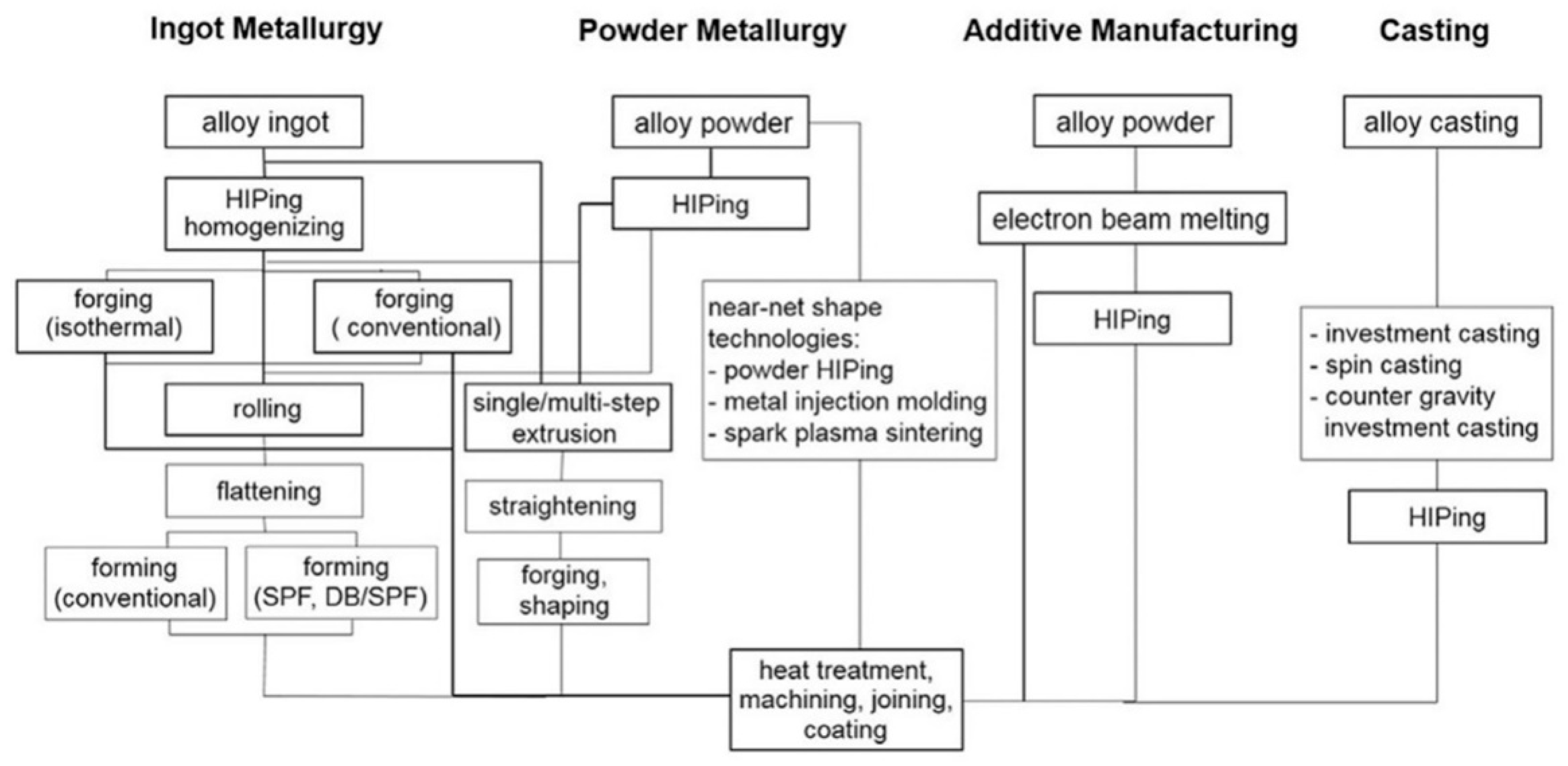
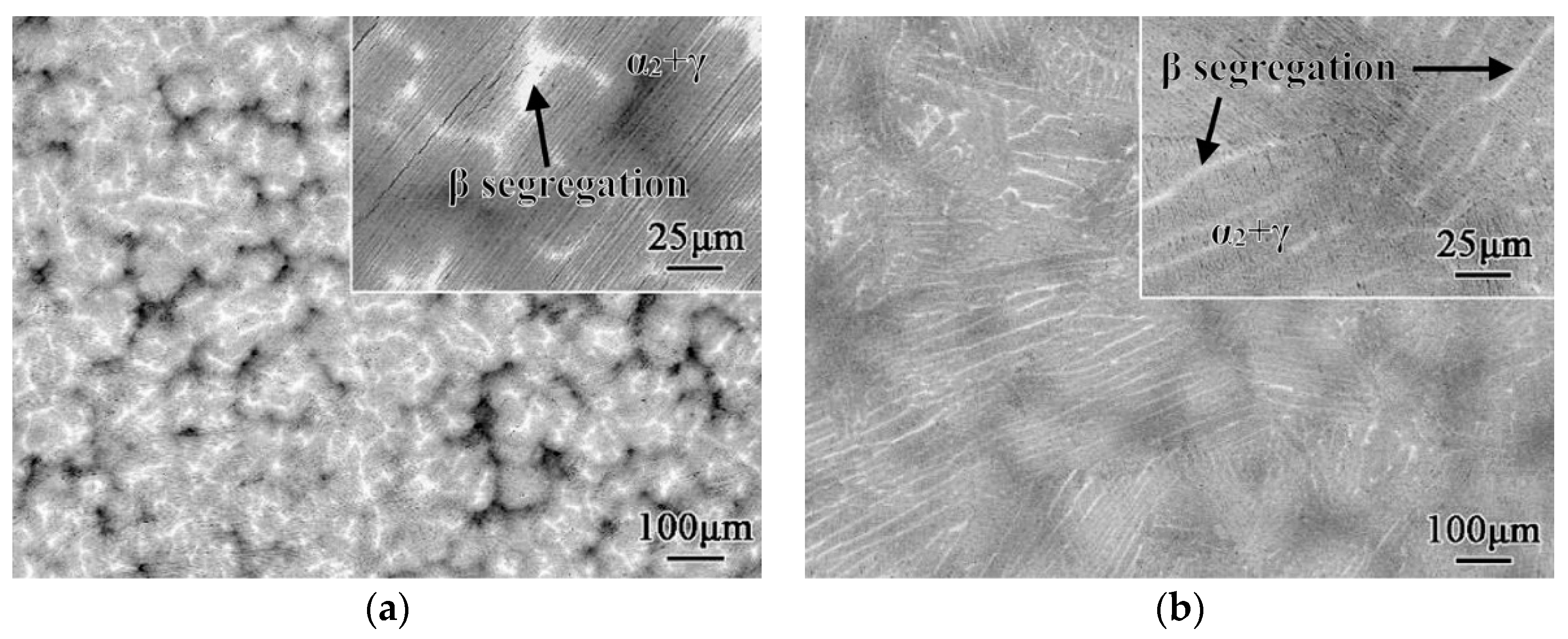
4. Microstructure Evolution in Processing and Heat Treatments

Proper processing technologies and heat treatments are also critical to the properties of materials in addition to the alloying elements which can stabilize different phases and strengthen materials. Four processing routes that are frequently used in γ TiAl alloys are shown in Figure 5: ingot metallurgy (IM), powder metallurgy (PM), additive manufacturing (AM) and casting. These routes usually need different shaping processes and heat treatments which result in distinct microstructure characteristics.

4.1. Ingot Metallurgy

Ingot metallurgy (IM) is a commonly used processing route for producing γ TiAl alloys. Alloy ingots can be manufactured by different melting techniques including plasma arc melting [68], vacuum arm melting [69], scull melting [70] and vacuum induction melting [71]. It is common to melt the alloys twice to increase melt homogeneity [69,70]. Additionally, Song et al. [72] provided an alternative technique, continuous combustion synthesis, which is also likely to be used to fabricate as-cast TiAl alloy.
Although the melting process is usually carried out under a vacuum or protective atmosphere, oxygen contamination is hard to completely avoid [73]. Oxygen contamination may come from impurities in the raw material, oxide crucibles and reactions between melt and O 2 . For example, directional solidified alloys usually have oxygen contamination and Y 2 O 3 particles inside the microstructure due to the use of Y 2 O 3 or Y 2 O 3 -coated crucibles [74,75]. Oxygen contamination was also found coming from calcia crucibles during vacuum induction melting [71]. In general, the oxygen contamination generated during melting is controlled below 1000 wt. ppm in industry, to avoid effects on solidification behavior [73] and phase transformations [76].
Through IM, both isotropic and anisotropic microstructures can be achieved by precisely selecting the Al content and solidification parameters. After that, the subsequent thermo-mechanical processes can refine grain size and improve the chemical homogeneity.
According to the binary phase diagram (Figure 4) within 42–48 at. % Al, γ TiAl alloys can either solidify through   L L + β β ( β solidification) with Al concentration lower than 44 at. % or solidify through L L + β α (peritectic solidification) with higher Al concentration. The two different final microstructures and main solidification steps of these two pathways are shown in Figure 6 and Figure 7, respectively, and will be discussed in detail in Section 4.1.1 and Section 4.1.2. However, the transition limit between peritectic and β solidifications can fluctuate around 44 at. % Al mainly because of two reasons. First, due to the addition of β stabilizers, the phase diagram has various kinds of shifting leading to the highest Al concentration limit for β solidification varies around 44–46 at. %. Readers could refer to the phase diagram of TNB and TNM alloys in [27,77]. Second, in an actual solidification situation, the solidification process may happen under non-equilibrium conditions and different elements may distribute inhomogeneously. Moreover, oxygen contamination formed during the casting trends to stabilize the α phase and then effects the solidification process [73]. Due to all the effects mentioned above, the transition Al limit may vary around 1.5 at. % [78,79]. As a result, The transition sequence may be changed into L L + β (dendritic) + α (interdendritic) lamellae ( α + γ ) + B2 or L L + β (dendritic) + γ (interdendritic) α 2 + γ + B2 [37,52,79,80,81]. The variation of solidification pathways can be solved by adjusting the composition of alloys or carefully controlling the casting parameter like cooling rates [82].
After casting, hot isostatic pressing (HIP) and forging are usually used to reduce the porosity and improve the strength and ductility [83]. Furthermore, forging can refine the lamellar colony size and shaping processes, such as rolling, extrusion and forming, create an ideal shape.

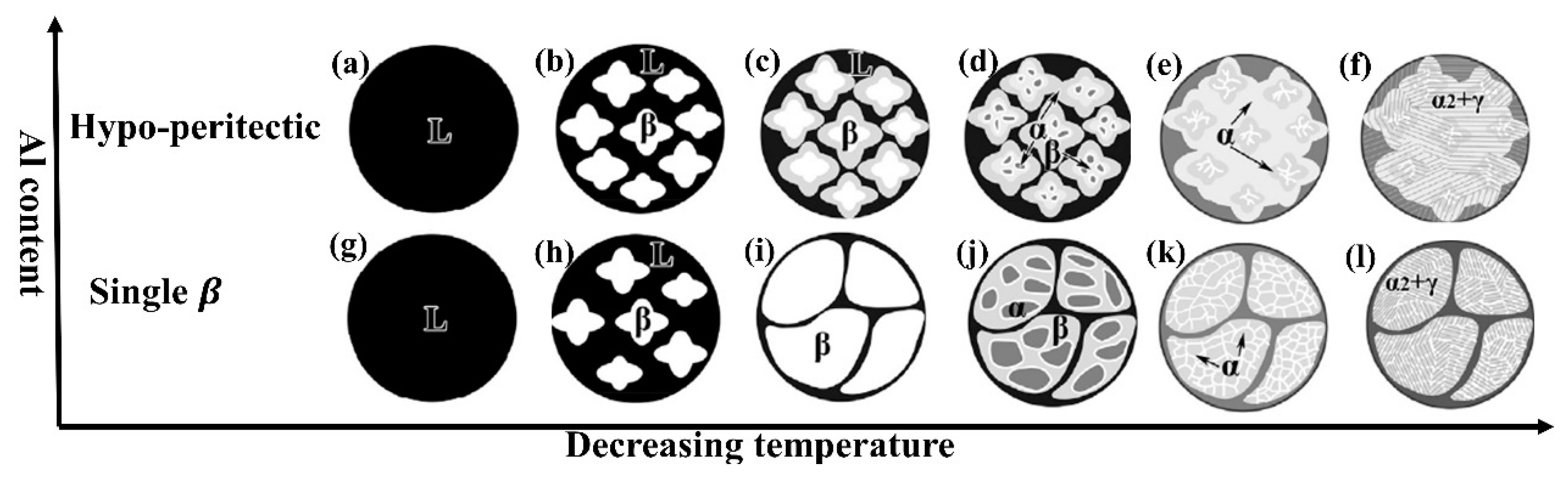
4.1.1. Peritectic Solidified Ingot

Third generation γ TiAl alloys, like TNM and TNB alloys, are β solidified alloys [2,84], but TNB alloys still go through some peritectic solidification in a non-equilibrium solidification condition [79]. Specifically, it will be hypo-peritectic solidification that contains some fraction of retained β phase. Its solidification pathway is L L + β α + β α α + γ α 2 + γ illustrated in Figure 7a–f.
The peritectic solidification can be divided into four steps resulting in an anisotropic microstructure with severe segregation and significant texture [1]. First, β dendrites form within the liquid as shown in Figure 7a,b. From Figure 7b,c, as the steep temperature gradient existing in the peritectic reaction, the nucleation rate of α phase is slow and its growth rate is fast. In this way, only one of the twelve Burger orientated variants of α phase is chosen to envelop β dendrite [84]. Next, during L + β α peritectic transformation (Figure 7c–e), the α phase grows up by dissolving the primary β phase and directly precipitating from the liquid. Finally, from Figure 7e,f, γ lamellae precipitate within α or α 2 grains following the Blackburn orientation relationship [37]. At the same time, segregations also show up during solidification in the interdendritic region, triple junctions of colonies and within colonies [70,85,86]. The formation of segregations may attribute to the inhomogeneous distribution of solute concentration, the addition of low diffusive β stabilizers, such as Nb and W, and the solidification path. Therefore, large grains with specific orientation and severe segregation form (Figure 6a).
The anisotropic characteristic of peritectic solidified alloys is utilized by directional solidification techniques resulting in two different microstructures. One is the columnar grain lamellae microstructure. For example, Ding et al. [68,74,79] achieved a close-complete peritectic solidification using TNB alloy by controlling the growth rate. The other one is polysynthetic twinned TiAl alloy (PST) with aligned fully lamellar colonies [28,87,88]. However, both directional solidification techniques are challenging to be used to produce large scale ingots.

4.1.2. 𝛽 Solidified Ingot

In comparison with peritectic solidification, solidifying completely through the β phase shows a texture-free microstructure with modest micro-segregation and fine grains (Figure 6b). The solidification pathway is L L + β β β + α β + α + γ β 0 + α 2 + γ showed in Figure 7g–l.
Through four main steps, an isotropic microstructure forms via β solidification. Firstly, from Figure 7g–i, β grains nucleate and grow up in the singe β phase temperature region. Secondly, the solid-state transformation β β + α happens when the temperature is lower than the β -transus temperature. The α phase nucleates heterogeneously at grain boundaries, triple points and borides leading to a reticular morphology (Figure 7i–k) [89,90]. The α grian nucleates at β grain boundaries along 12 possible Burger directions, and also nucleates at borides which give a random orientation [46,84]. Meanwhile, the β stabilized elements diffuse into the β phase. Then, the isolated γ grains nucleate from remnant β   grains. This leads to the contiguous distribution of γ and β grains [90]. Finally, from Figure 7k,l, ( α 2 + γ ) lamellar sturcture forms.
There are two typical β solidified alloys: TNM alloys and TNM+ alloys. Clemens et al. found [91] that these alloys exhibit an adjustable β phase volume fraction which is favorable in thermal mechanical processes. During thermo-mechanical processes, the β phase greatly increases the deformability. The wide ( α + γ + β ) coexisting region makes TNM and TNM+ alloys can adapt non-isothermal conventional forging processes. After that, the β phase need to be eliminated by heat treatment, because it reduced the RT ductility. The forged alloy need lower heat treatment temperature than the as-cast alloy to achieve the same mechanical properties [27].

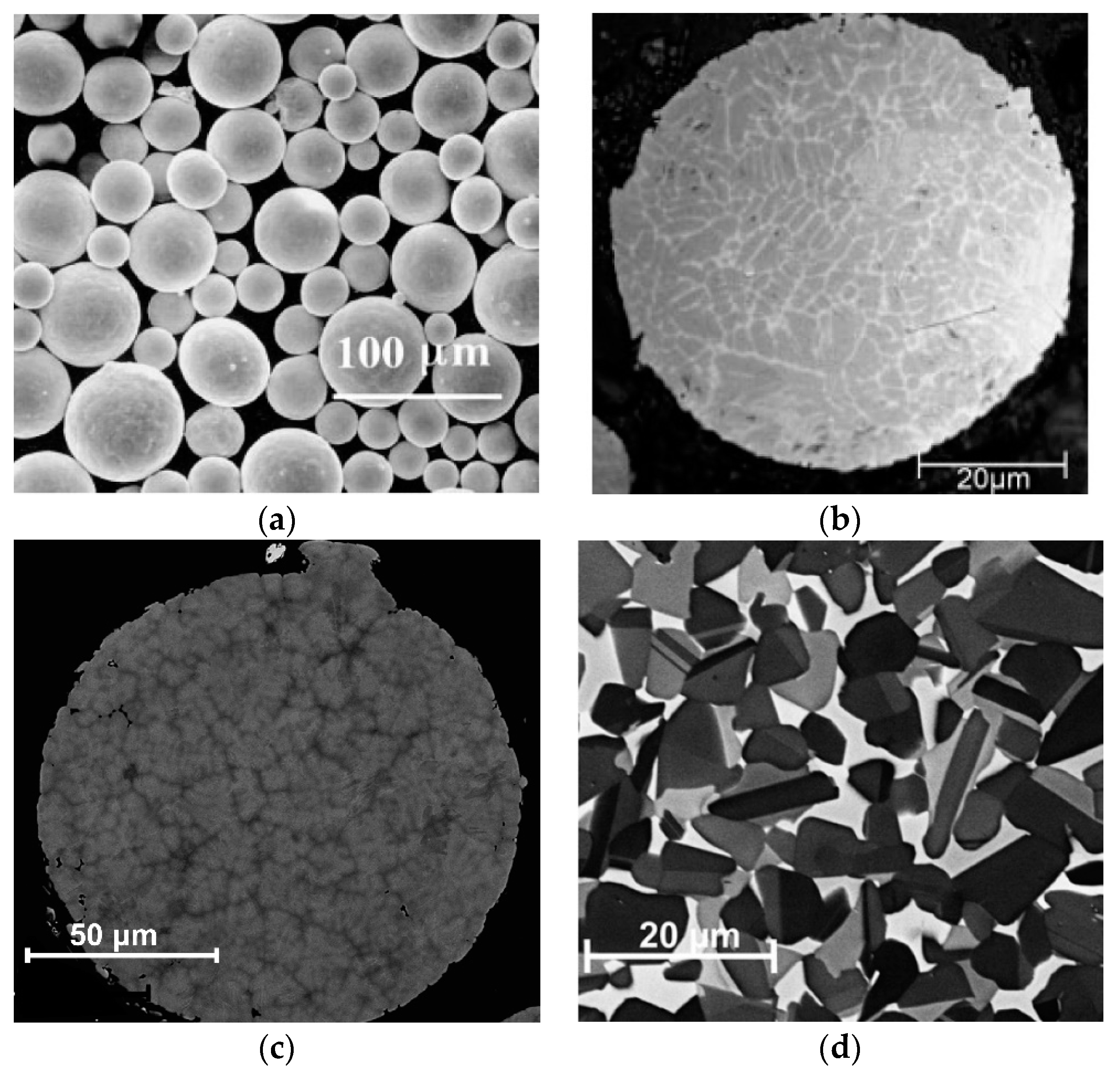
4.2. Powder Metallurgy and Compaction

Powder metallurgy (PM) has also attracted great interest because of the homogenous element distribution and reproducibility. With the assistant of compaction, PM provides a homogenous and dense material with a segregation-free and fine-grained microstructure [92,93]. Powder particles, the raw materials, are produced by atomization processes, including argon, helium and centrifugal atomization with a high cooling rate. Argon gas atomization could produce the lowest inner gas contained powders among three atomization processes [36,94]. Figure 8a shows powders obtained by this process. The microstructure of the powder particle depends on the alloy composition and the solidification technique. For peritectic solidified alloys, the particles consist of a large fraction of γ phase and a minor fraction of α phase (see Figure 8b) [36]. For typical β solidified alloys, such as TNM, the particles are mainly composed of α phase and β / β 0 phase (see Figure 8c) [92]. Gerling et al. [36] have also demonstrated that the cooling rate and different atomization techniques lead to different phase volume fractions in the particle. Powders that have unique microstructures and distinct phase compositions can be chosen for this process. The initial microstructure would affect the resulting microstructure and properties after HIP and heat treatment process [36].
Besides gas atomization processes, an alternative power production technique through aluminothermic reduction is also worth being pointed out because of its low production cost, high productivity and simple production process. Typically, there are three types of low-cost reductants in the aluminothermic reduction process: T i C l 4 [95], fluotitanate [96] and T i O 2 [97] where the former two are used to produce powder particles. For example, Haidar et al. [95] demonstrated that aluminothermic reduction process through T i C l 4 is able to produce γ T i A l alloy powders with added elements like Nb and Mo. Kun Zhao et al. proposed a two-stage aluminothermic reduction process, which uses N a 2 T i F 6 to fabricate T i 3 A l , T i A l and T i A l 3 loose sponge-like powder, separately [96].
There are two main processes used to densify powders: HIP and spark plasma sintering (SPS). HIP is usually conducted at 1000–1300 °C for 2–4 h with a pressure between 150–200 MPa [36]. After that, equiaxed grains with a narrow grain size distribution are obtained (see Figure 8d). To obtain other typical microstructures, future heat treatment is needed [92]. SPS is another technique used to densify the microstructure of a wide range of compositions of γ TiAl alloys [98]. In the SPS process, various processing temperatures lead to different microstructures. In the low temperature region, the powder particles transform into γ grains. Then, increasing temperature into ( α + γ ) phase region results in DP and NLγ microstructures. The NLβ microstructure is formed by conducting SPS in the single β phase region [99]. Moreover, Voisin et al. [99] found that heat treatment after SPS can improve the homogeneity of the microstructure, but the ductility could not be improved obviously. An alternative way to a heat treatment after SPS is a further extension of sintering time from 2 to 30 min. It could improve the creep resistance of DP microstructure but also could lead to continuing coarsening of the microstructure [15,99].

4.3. Additive Manufacturing and Casting

Additive manufacturing (AM) is an alternative process to produce complex near-net-shape components based on high-quality powders. There are usually three methods: electron beam melting [3,4,100,101], laser melting [102] and selective laser melting [103]. Among them, the electron beam melting process shows the highest potential to be used in manufacturing γ TiAl alloys, due to its high technical readiness level [104]. AM is used to produce 4822TiAl alloy as well as Ti–(47–48)Al–2Cr–8Nb alloy [100,101]. HIP process can be used to reduce the porosity further. For example, around 2% of porosity in 4822TiAl alloy formed during AM can be eliminated by a subsequent HIP [101]. However, the extensive use of AM is still limited by high cost, instability of mechanical properties and the difficulty of producing large scale components [104]. In recent years, BMBF alloys have been designed to adapt to the AM method. These alloys solidified peritectically but could obtain an isotropic microstructure after subsequent heat treatment [4]. These alloys show a considerable potential to be manufactured on an industrial scale.
The casting technique is the most cost-effective manufacturing process used in the second generation TiAl alloy to produce units with complex shapes. It was used to produce the first commercial TiAl alloy (4822TiAl alloy) used as low pressure turbines [6,8]. However, the common drawbacks of the casting technique are the inhomogeneity of microstructures and casting defects [8]. Although part of the casting defects can be eliminated by HIP, there are dimples on the surface leading to a high reject rate [6,105].

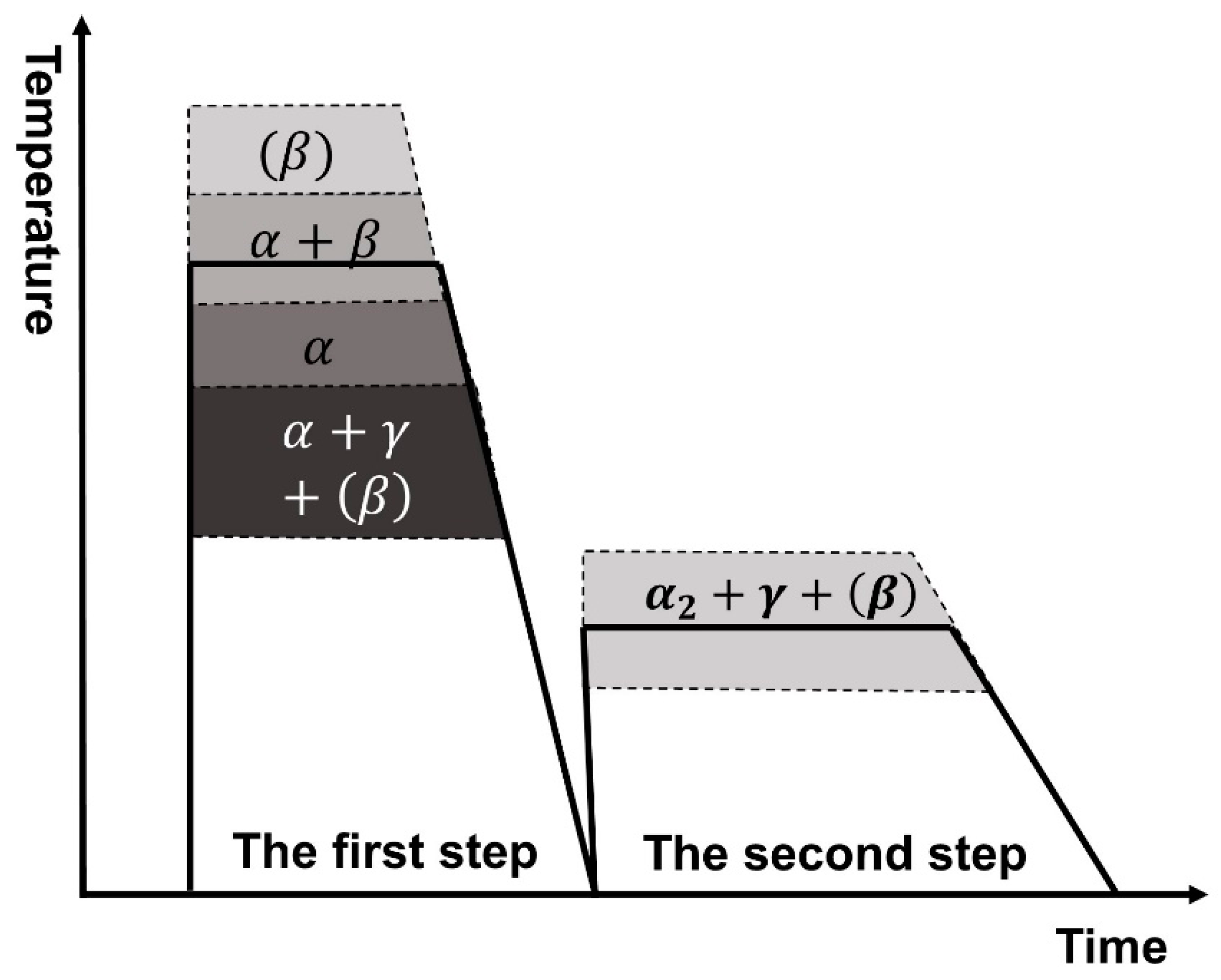
4.4. Heat Treatments

There are still remaining defects and inhomogeneity of microstructures after IM, PM and AM processing. Therefore, heat treatments are used to adjust microstructures and optimize mechanical properties. For example, heat treatments after IM processing can eliminate the remained segregations after forging [86]. The heat treatment after PM can improve the microstructure homogeneity and adjust the phase fraction. Furthermore, γ TiAl alloys manufactured by AM have a common problem that is the Al content varies within layers. Through heat treatments, the microstructure can be homogenized [4]. In summary, heat treatments can achieve a homogenous microstructure without severe segregation.
A two-step heat treatment (see Figure 9) has been widely used after IM, PM and AM routes because it could optimize microstructures and balance mechanical properties [4,99,106,107]. The first step heat treatment can adjust phase fraction and the size of α grains which determines the final lamellar colony size. The second step heat treatment can control the lamellar spacing and bring γ TiAl alloys closer to thermal equilibrium.
The first step heat treatment could be conducted at a wide range of phase regions and different kinds of microstructures could be obtained. Four different phase regions are shown in Figure 9 and discussed in the following from low to high temperature phase region. Heat treatment in ( α + γ + ( β ) ) phase region leads to the presence of ( γ + ( β ) ) grains within the α matrix as what has been discussed in Section 2.2. Usually, heat treatment under a single α phase region should be avoided due to the severe coarsening effect. However, the process-adapted alloy, TNM+, can achieve a fine fully lamellar structure by conducting first-step heat treatment within the single α phase region, due to the presence of silicides and borides [5]. Further increase of temperature of heat treatment within ( α + β ) phase region, γ grains would disappear and leave with NLβ structure. When the alloys are heated in ( α + γ + ( β ) ), single α   and ( α + β ) regions, the grain size of the supersaturated α phase will increase leading to the increment of colony size in the final microstructure [26]. For β solidified alloys, the heat treatment can be conducted in the single β region offered NLβ microstructures [27]. The fast diffusion rate at high temperature homogenizes the final microstructure and reduce segregations. In all different phase regions, the selection of cooling rate after the first heat treatment is critical which can control the growth of γ lamellae. The fast cooling rate may inhibit the lamellar structure showing up and then supersaturated α grains is preserved [108,109]. The non-equilibrium state could be adjusted by a second step heat treatment.
The second step heat treatment is usually conducted within the ( α 2 + γ + ( β ) ) phase region. During the heat treatment, fine γ lamellae can form either through discontinuous precipitation or cellular reaction depending on solidification conditions. The growth of fine γ -lamellae within supersaturated α grains and β / β 0 grains, and the local refinement through cellular reaction, both can bring the alloys close to thermodynamic equilibrium conditions [110]. However, discontinuous precipitation should be avoided because it reduces the creep resistance and yield strength [55,111]. After second step heat treatment, furnace cooling is the most common choice to obtain thermal equilibrium microstructures [106].
In the most recent decade, alternative heat treatment processes had been investigated. A time saving single step heat treatment that can refine lamellar colony structure were proposed for IM [112]. The single step heat treatment is also used in various AM alloys [100,101]. Different heat treatment temperatures can obtain DP microstructures and FL microstructures. Moreover, Schwaighofer et al. [27] explored the resulting alloy microstructures and mechanical properties after three step heat treatment and cyclic heat treatment.

5. Effect of Microstructures on Mechanical Properties

5.1. Creep Resistance

Creep resistance is a crucial property that determines the service temperature limit. Current research on creep resistance of γ TiAl alloys primarily focuses on the volume fraction of γ grains, the presence of β 0 / ω 0 phase, lamellar interface spacing and addition elements.
Microstructures with different γ grain volume fractions have diverse abilities against creep deformation. As γ grains are not effective obstacles, the unconstrainted movement of dislocations degrades creep resistance [113]. FL microstructures have the best performance in creep resistance among four typical microstructures and also single phase TiAl alloys, due to the absence of γ grains and the high grain boundary density within the lamellar structure which could hinder dislocation movements [114]. NL and DP microstructures which contain less than 20% γ grains (usually less than 100 μm), are generally located between colony boundaries and they have poorer creep resistance than F L microstructure [115]. By contrast, NG microstructures contain more γ grains than other typical microstructures and its creep behavior is largely determined by the percentage of γ grains.
The stabilized β 0 phase also affects creep property. The β 0 phase at colony boundaries can reduce the creep resistance because it facilitates the grain boundary sliding [113]. However, the effect of β 0 / ω 0 grains is still under debate. Bolz et al. [108] explained that β 0 / ω 0 grains seem to improve creep resistance. On the contrary, Liu et al. [116] demonstrated that the ω 0 phase grow within β 0 phase and also precipitate inside α 2 lamellae accelerating creep failure.
In the study of FL or NL microstructures, the change of lamellar spacing plays one of the most crucial roles in affecting creep resistance. The colony size (larger than 100 μm) and volume fraction of α 2 and γ phases do not affect the creep resistance effectively [117]. The creep resistance is governed by different mechanisms depending on the lamellar spacing. For lamellar spacing in the submicron scale, the primary creep regime is controlled by the interaction processes of dislocation-dislocation and dislocation-obstacles [118]. The secondary creep is a diffusion-controlled process that can be characterized by
ε ˙ s σ n e x p ( Q a p p / k T )
where k is the Boltzmann’s constant and Q a p p is the apparent activation energy. For lamellar spacing of a few nanometers, the dislocation motion within lamellae is blocked. The deformation mechanism was found primarily due to the motion of interfacial ledges, assisted by the jog-pair formation process [5]. In summary, the decrease of lamellar spacing from submicron to nanoscale hinders parts of the dislocation movement, resulting in the enhancement of creep resistance [5,55,118].
Another important factor that effects the creep resistance is the addition of different elements: Si, C and Nb. As mentioned in Section 3.2, C and Si improve creep resistance by forming solid solutions and precipitates. The refinement of lamellar structure and inhibition of discontinuous precipitation can also improve creep resistance [113]. For instance, Silicides can pin at the grain boundary keeping the α grain size in the same magnitude after heat treatment in the single α phase region [113]. C can also refine the lamellar structure to hinder the dislocation movement [56]. Additionally, C and Si solid solutions improve the phase stability and inhibit discontinuous precipitation reaction because Si and C are strong partition elements [55,64]. Furthermore, Nb can reduce the stacking fault energy leading to the increase of creep resistance [29].

5.2. Dctility

In general, the RT ductility of γ TiAl alloys is in the region of 0.5–3%. When the temperature increase to 700–750 °C the alloy will experience a brittle to ductile transition and the ductility is increased [26,83]. Several factors affect the ductility, including segregations and precipitates, phase volume fraction, lamellar orientation and colony size.
The presence of segregations and precipitates, such as boride ribbon, is detrimental to ductility. For example, in TNB alloy, the ductility of the as-cast alloy is decreased because of the formation of large boride ribbons and segregations. After forging, the refined boride precipitates, partially eliminated segregations and the increase of γ grain fraction all result in the increase of ductility. Therefore, the DP microstructures formed after canned forging demonstrate better ductility at RT and high temperature than the as-cast NL microstructures [83,119].
Ductility is also affected by the γ grain volume fraction, γ lath volume fraction and β phase volume fraction. Among four typical microstructures, the NG microstructure has the best ductility due to the large fraction of γ grain and is followed by DP, NL and FL microstructures [120]. Several studies have focused on the relationship between γ   lath and ductility. Chauniyal et al. [121] reported that the γ -lath fraction is the dominant factor when the load direction is parallel to the lamellar interface, while the lamellar spacing is the dominant factor when the loading direction is perpendicular to the semi-coherent lamellar interface by atomistic simulation. Droessler et al. [110] reported that the increase of γ -lath fraction leads to a substantial increment of RT strain without changing the hardness greatly. The γ -lath fraction can be raised by increasing the second step heat treatment temperature within the ( α 2 + γ ) region. Furthermore, the ductility can also be improved by eliminating the β / β 0 phase as β 0 phase is brittle at RT [99,110].
Except for the phase volume fraction, the lamellar orientation also effects the ductility, due to the anisotropic lamellar structure. As mentioned in Section 4.1.1, directional solidification can align the lamellar orientation. The ductility of aligned microstructures can vary with the angle between lamellar orientation and the loading direction [88]. For example, Chen et al. [87] used the directional solidification method to produce well-aligned 0°-orientation PST structure that exhibits excellent ductility in the range of 6.3–7.6%. Yamaguchi et al. [88] found that the tensile ductility is close to zero when the loading direction is perpendicular to the lamellar interface.
For ( α 2 + γ ) colony size larger than 100 μm, the decrease of colony size also increases the ductility and does not affect the creep resistance [114,122]. When the colony size is less than 100 μm, dynamic recrystallization may occur lead to the increase of creep rate [114]. In addition, a narrow size distribution also contributes to the improvement of ductility [92].

5.3. Strength and Hardness

Third generation γ TiAl alloys exhibit excellent strength at both RT and high temperature with the addition of 4–10 at. % Nb. For TNM alloys, the yield strength at RT is usually within the range of 700–1000 MPa where a NLβ microstructure with 25–50 nm lamellar spacing achieved the maximum strength [27]. High Nb containing TiAl alloys, because of the solid solution strengthening effect of Nb addition, could achieve yield strength up to 1.15 GPa at RT and up to 750 MPa at 800 °C, which is significantly higher than second generation γ TiAl alloys. [123].
Aside from Nb addition, strength is also effected by various factors, including phase fraction and lamellar spacing. Since the hardness of microstructures is greatly related to the strength of the material [124], the strength of the material is effected by the volume fraction of phases with different hardness. The understanding of nano-hardness of various phases helps in the design of microstructure. Previously, the presence of fine ω 0 phase in the β 0 phase is hard to be observed in SEM image, so the β 0 phase is considered as the hardest phase among α 2 , γ and β 0 grains [45,92]. The latter study showed that the high hardness of β 0 phase is caused by the presence of ω 0 phase within it. The hardness relation is ( β 0 + ω 0 ) > ω 0 > α 2 > β 0 > γ [45]. Therefore, a high percentage ( β 0 + ω 0 ) phase could improve the strength but also could lead to brittle behavior.
Additionally, strength is also affected by the width of γ lath and the grain size of the lamellar colony. For large grain size, the strength and grain size obey the Hall–Petch relationship.
σ y = σ 0 + k d 1 2
where σ y , σ 0 and d are the yield strength, intrinsic strength and grain size, respectively [32,122]. The fine lamellar lath also follows the modified Hall–Petch effect which shows an inverse relationship between the strength and the lamellar spacing [106,125]. Consequently, the fine γ -lamellae usually formed during the second step heat treatment reduces the average lamellar spacing, and result in increased hardness and strength. By adjusting the phase fraction and microstructure, the macro-hardness, as well as the strength, can be controlled. For DP microstructures, the presence of a large fraction of γ grains leads to lower yield strength than the lamellar structure [32]. Schwaighofer et al. [27] demonstrated that the strength of NLγ microstructure increases by decreasing the γ phase fraction but it is still smaller than the FL microstructure.
It is also critical to balance these properties in the material because a pronounced ductility would lead to a decrease in yield strength and creep resistance. A small fraction of 𝛾 grains could improve the ductility but reduce the strength and hardness. It seems that the NLγ microstructure exhibits better ductility than the FL microstructure and higher creep resistance than the DP microstructure [22,99]. In summary, NL microstructures show a better balance performance between ductility and creep resistance than other microstructures.

6. Summary and Outlook

Based on research on γ TiAl alloys in the past decades, this review focuses on how to achieve desired mechanical properties by tailoring the microstructure, which is strongly correlated with chemical composition, processing technologies and heat treatments.
First, the addition of different elements affects microstructure evolution and modifies mechanical properties. Nb, Mo, Ta, W, Mn, V and Cr stabilize the bcc β phase, thus increasing the hot workability of alloys. B, Si and C additions can change and refine microstructures and enhance creep resistance through forming a solid solution or precipitations due to their limited solubility. Second, processing technologies and subsequent heat treatments also play an essential role in the microstructure design. Solidification pathways effect all processing routes, including PM and IM, so a judicious choice of processing parameters is required. HIP and SPS are two widely used processes that result in a densified microstructure. After that, proper heat treatment processes refine microstructures and balance mechanical properties. Finally, there are three majority phases and four typical microstructures in γ TiAl alloys which display varied mechanical behaviors. With proper addition elements, processing technologies and heat treatment routes, superior mechanical properties can be achieved.
Overall, this light-weight and high-temperature material illustrates a bright prospect for extensive use in aerospace and automotive industries, especially when humanity is facing an increasing number of problems rising from climate change, the environment and energy fields. In recent years, researchers have focused on the development of the fourth generation of γ TiAl alloys for which the service temperature increases up to 850 °C [4].
A deeper and more fundamental understanding of the microstructure evolution mechanism would accelerate the improvement of mechanical properties and processibility of this intermetallic. Although effects of microstructure on the mechanical properties of γ TiAl alloys has been widely studied, common microstructure test methods, even ex situ TEM experiments, hardly provide real-time experimental data at the atomic scale. Without the most reliable experimental data, which displays the evolution of microstructure and damage mechanism in service conditions, the improvement of alloy composition design and processing technology face many challenges. Therefore, in situ investigations of the relationship between microstructure evolution and mechanical properties, as well as theoretical simulation on microstructure evolution, have received increasing attention. For example, the β phase plays an important role in expanding the hot-working window, while it is not favored in service conditions. Precise information about its microstructure evolution at varied temperature regions and under different loading conditions provides more clues. Similarly, the addition of Si also attracts much attention because it is able to improve creep resistance and corrosion resistance, but the formation mechanism of silicide is still controversial. In situ investigations at the atomic scale, combining theoretical simulations, could be used to provide solid answers.
At the same time, alternative processing technologies and routes, such as aluminothermic reduction [96] and single step heat treatment [112], aim to reduce production costs. Moreover, additive manufacturing, which has shown a great potential to produce complex components directly, has been widely investigated to broaden the application of the TiAl alloy. However, the control of evaporation and uneven distribution of Al during AM is an urgent problem that remains to be solved.
Finally, although there are still quite a few unexplored fundamental research questions and many challenges in the applications of γ TiAl alloys, there is much to look forward to in the future. By combining advanced experimental methods and theoretical simulations, more phenomena and mechanisms of   γ TiAl alloys await to be discovered. Based on them, the industrial application of   γ TiAl alloys will be wider and more promising.

Author Contributions

Conceptualization: Q.L., X.L., W.Z. and L.C.; Investigation: X.L. and Q.L.; Resources: L.C., W.Z., Q.L. and X.L.; Writing—original draft preparation: X.L. and Q.L.; Writing—review and editing: X.L., Q.L., W.Z., L.C. and C.V.H.; Supervision: L.C. All authors have read and agreed to the published version of the manuscript.

Funding

This research was funded by ‘Climbing Plan’ Project, grant number pdjh2020b0724 and Guangdong Platform and Key Projects, grant number 2018KTSCX281.

Data Availability Statement

No new data were created or analyzed in this study. Data sharing is not applicable to this article.

Conflicts of Interest

The authors declare no conflict of interest.

References

  1. Kim, Y.W. Ordered intermetallic alloys, part III: Gamma titanium aluminides. JOM 1994, 46, 30–39. [Google Scholar] [CrossRef]
  2. Clemens, H.; Mayer, S. Design, processing, microstructure, properties, and applications of advanced intermetallic TiAl alloys. Adv. Eng. Mater. 2013, 15, 191–215. [Google Scholar] [CrossRef]
  3. Reith, M.; Franke, M.; Schloffer, M.; Körner, C. Processing 4th generation titanium aluminides via electron beam based additive manufacturing–characterization of microstructure and mechanical properties. Materialia 2020, 14, 100902. [Google Scholar] [CrossRef]
  4. Wimler, D.; Lindemann, J.; Reith, M.; Kirchner, A.; Allen, M.; Vargas, W.G.; Franke, M.; Klöden, B.; Weißgärber, T.; Güther, V.; et al. Designing advanced intermetallic titanium aluminide alloys for additive manufacturing. Intermetallics 2021, 131. [Google Scholar] [CrossRef]
  5. Klein, T.; Usategui, L.; Rashkova, B.; Nó, M.L.; San Juan, J.; Clemens, H.; Mayer, S. Mechanical behavior and related microstructural aspects of a nano-lamellar TiAl alloy at elevated temperatures. Acta Mater. 2017, 128, 440–450. [Google Scholar] [CrossRef]
  6. Bewlay, B.P.; Weimer, M.; Kelly, T.; Suzuki, A.; Subramanian, P.R. The Science, Technology, and Implementation of TiAl Alloys in Commercial Aircraft Engines. MRS Proc. 2013, 1516, 49–58. [Google Scholar] [CrossRef]
  7. Kim, Y.W.; Kim, S.L. Advances in Gammalloy Materials–Processes–Application Technology: Successes, Dilemmas, and Future. JOM 2018, 70, 553–560. [Google Scholar] [CrossRef] [Green Version]
  8. Bewlay, B.P.; Nag, S.; Suzuki, A.; Weimer, M.J. TiAl alloys in commercial aircraft engines. Mater. High Temp. 2016, 33, 549–559. [Google Scholar] [CrossRef]
  9. Schuster, J.C.; Palm, M. Reassessment of the binary aluminum-titanium phase diagram. J. Phase Equilibria Diffus. 2006, 27, 255–277. [Google Scholar] [CrossRef]
  10. Stark, R.; Bartels, A.; Clemens, H.; Schimansky, F.P. On the formation of ordered ω-phase in high Nb containing TiAI based alloys. Adv. Eng. Mater. 2008, 10, 929–934. [Google Scholar] [CrossRef] [Green Version]
  11. Stark, A.; Oehring, M.; Pyczak, F.; Schreyer, A. In situ observation of various phase transformation paths in Nb-rich TiAl alloys during quenching with different rates. Adv. Eng. Mater. 2011, 13, 700–704. [Google Scholar] [CrossRef]
  12. Bendersky, L.A.; Boettinger, W.J.; Burton, B.P.; Biancaniello, F.S.; Shoemaker, C.B. The formation of ordered ω-related phases in alloys of composition Ti4Al3Nb. Acta Metall. Mater. 1990, 38, 931–943. [Google Scholar] [CrossRef]
  13. Song, L.; Xu, X.J.; You, L.; Liang, Y.F.; Lin, J.P. Phase transformation and decomposition mechanisms of the βo(ω) phase in cast high Nb containing TiAl alloy. J. Alloys Compd. 2014, 616, 483–491. [Google Scholar] [CrossRef]
  14. Schmoelzer, T.; Liss, K.D.; Zickler, G.A.; Watson, I.J.; Droessler, L.M.; Wallgram, W.; Buslaps, T.; Studer, A.; Clemens, H. Phase fractions, transition and ordering temperatures in TiAl-Nb-Mo alloys: An in- and ex situ study. Intermetallics 2010, 18, 1544–1552. [Google Scholar] [CrossRef]
  15. Clemens, H.; Wallgram, W.; Kremmer, S.; Güther, V.; Otto, A.; Bartels, A. Design of novel β-solidifying TiAl alloys with adjustable β/B2-phase fraction and excellent hot-workability. Adv. Eng. Mater. 2008, 10, 707–713. [Google Scholar] [CrossRef]
  16. Burgers, W. On the process of transition of the cubic-body-centered modification into the hexagonal-close-packed modification of zirconium. Physica 1934, 1, 561–586. [Google Scholar] [CrossRef]
  17. Blackburn, M.J. Some Aspects of Phase Transformations in Titanium Alloys. In The Science, Technology and Application of Titanium; Elsevier: Amsterdam, The Netherlands, 1970; pp. 633–643. [Google Scholar] [CrossRef]
  18. Kim, Y.W.; Dimiduk, D.M. Progress in the understanding of gamma titanium aluminides. JOM 1991, 43, 40–47. [Google Scholar] [CrossRef]
  19. Appel, F.; Wagner, R. Microstructure and deformation of two-phase γ-titanium aluminides. Mater. Sci. Eng. R Rep. 1998, 22, 187–268. [Google Scholar] [CrossRef]
  20. Clemens, H.; Kestler, H. Processing and applications of intermetallic γ-TiAl-based alloys. Adv. Eng. Mater. 2000, 2, 551–570. [Google Scholar] [CrossRef]
  21. Kothari, K.; Radhakrishnan, R.; Wereley, N.M. Advances in gamma titanium aluminides and their manufacturing techniques. Prog. Aerosp. Sci. 2012, 55, 1–16. [Google Scholar] [CrossRef]
  22. Kim, Y.W. Microstructural evolution and mechanical properties of a forged gamma titanium aluminide alloy. Acta Metall. Mater. 1992, 40, 1121–1134. [Google Scholar] [CrossRef]
  23. Clemens, H.; Bartels, A.; Bystrzanowski, S.; Chladil, H.; Leitner, H.; Dehm, G.; Gerling, R.; Schimansky, F.P. Grain refinement in γ-TiAl-based alloys by solid state phase transformations. Intermetallics 2006, 14, 1380–1385. [Google Scholar] [CrossRef]
  24. Yamaguchi, M.; Inui, H.; Ito, K. High-temperature structural intermetallics. Acta Mater. 2000, 48, 307–322. [Google Scholar] [CrossRef]
  25. Kim, Y.W. Intermetallic alloys based on gamma titanium aluminide. JOM 1989, 41, 24–30. [Google Scholar] [CrossRef]
  26. Cui, N.; Wu, Q.; Bi, K.; Xu, T.; Kong, F. Effect of heat treatment on microstructures and mechanical properties of a novel β-solidifying TiAl alloy. Materials 2019, 12, 1672. [Google Scholar] [CrossRef] [Green Version]
  27. Schwaighofer, E.; Clemens, H.; Mayer, S.; Lindemann, J.; Klose, J.; Smarsly, W.; Güther, V. Microstructural design and mechanical properties of a cast and heat-treated intermetallic multi-phase γ-TiAl based alloy. Intermetallics 2014, 44, 128–140. [Google Scholar] [CrossRef]
  28. Inui, H.; Oh, M.H.; Nakamura, A.; Yamaguchi, M. Room-temperature tensile deformation of polysynthetically twinned (PST) crystals of TiAl. Acta Metall. Mater. 1992, 40, 3095–3104. [Google Scholar] [CrossRef]
  29. Dehm, G.; Motz, C.; Scheu, C.; Clemens, H.; Mayrhofer, P.H.; Mitterer, C. Mechanical size-effects in miniaturized and bulk materials. Adv. Eng. Mater. 2006, 8, 1033–1045. [Google Scholar] [CrossRef]
  30. Cha, L.; Clemens, H.; Dehm, G. Microstructure evolution and mechanical properties of an intermetallic Ti-43.5Al-4Nb-1Mo-0.1B alloy after ageing below the eutectoid temperature. Int. J. Mater. Res. 2011, 102, 703–708. [Google Scholar] [CrossRef]
  31. Cha, L.; Scheu, C.; Clemens, H.; Chladil, H.F.; Dehm, G.; Gerling, R.; Bartels, A. Nanometer-scaled lamellar microstructures in Ti-45Al-7.5Nb-(0; 0.5)C alloys and their influence on hardness. Intermetallics 2008, 16, 868–875. [Google Scholar] [CrossRef]
  32. Kim, Y.W. Strength and ductility in TiAl alloys. Intermetallics 1998, 6, 623–628. [Google Scholar] [CrossRef]
  33. Voice, W.E.; Henderson, M.; Shelton, E.F.J.; Wu, X. Gamma titanium aluminide, TNB. Proc. Intermet. 2005, 13, 959–964. [Google Scholar] [CrossRef]
  34. Huang, S.C. Structural Intermetallics; Darolia, R., Lewandowski, J.J., Liu, C.T., Martin, P.L., Miracle, D.P., Nathal, M.V., Eds.; TMS: Warrendale, PA, USA, 1993; pp. 299–308. [Google Scholar]
  35. Kainuma, R.; Fujita, Y.; Mitsui, H.; Ohnuma, I.; Ishida, K. Phase equilibria among α (hcp), β (bcc) and γ (L10) phases in Ti-Al base ternary alloys. Intermetallics 2000, 8, 855–867. [Google Scholar] [CrossRef]
  36. Gerling, R.; Clemens, H.; Schimansky, F.P. Powder metallurgical processing of intermetallic gamma titanium aluminides. Adv. Eng. Mater. 2004, 6, 23–38. [Google Scholar] [CrossRef]
  37. Imayev, R.M.; Imayev, V.M.; Oehring, M.; Appel, F. Alloy design concepts for refined gamma titanium aluminide based alloys. Intermetallics 2007, 15, 451–460. [Google Scholar] [CrossRef]
  38. Shaaban, A.; Signori, L.J.; Nakashima, H.; Takeyama, M. Effects of the addition of transition metals on phase equilibria and phase transformations in TiAl systems in between 1473 and 1073 K. J. Alloys Compd. 2021, 878, 160392. [Google Scholar] [CrossRef]
  39. Jabbar, H.; Monchoux, J.P.; Thomas, M.; Pyczak, F.; Couret, A. Improvement of the creep properties of TiAl alloys densified by Spark Plasma Sintering. Intermetallics 2014, 46, 1–3. [Google Scholar] [CrossRef] [Green Version]
  40. Liu, B.; Liu, Y.; Li, Y.P.; Zhang, W.; Chiba, A. Thermomechanical characterization of β-stabilized Ti-45Al-7Nb-0.4W-0. 15B alloy. Intermetallics 2011, 19, 1184–1190. [Google Scholar] [CrossRef]
  41. Watson, I.J.; Liss, K.D.; Clemens, H.; Wallgram, W.; Schmoelzer, T.; Hansen, T.C.; Reid, M. In situ characterization of a Nb and Mo containing γ-TiAl based alloy using neutron diffraction and high-temperature microscopy. Adv. Eng. Mater. 2009, 11, 932–937. [Google Scholar] [CrossRef]
  42. Qiang, F.; Kou, H.; Yang, G.; Tang, B.; Li, J. Multi-step heat treatment design for nano-scale lamellar structures of a cast Ti-45Al-8.5Nb-(W, B, Y) alloy. Intermetallics 2016, 79, 35–40. [Google Scholar] [CrossRef]
  43. Sun, F.S.; Cao, C.X.; Kim, S.E.; Lee, Y.T.; Yan, M.G. Alloying mechanism of beta stabilizers in a TiAl alloy. Metall. Mater. Trans. A Phys. Metall. Mater. Sci. 2001, 32, 1573–1589. [Google Scholar] [CrossRef]
  44. Ye, L.H.; Wang, H.; Zhou, G.; Hu, Q.M.; Yang, R. Phase stability of TiAl-X (X=V, Nb, Ta, Cr, Mo, W. and Mn) alloys. J. Alloys Compd. 2020, 819, 153291. [Google Scholar] [CrossRef]
  45. Schloffer, M.; Rashkova, B.; Schöberl, T.; Schwaighofer, E.; Zhang, Z.; Clemens, H.; Mayer, S. Evolution of the ωo phase in a β-stabilized multi-phase TiAl alloy and its effect on hardness. Acta Mater. 2014, 64, 241–252. [Google Scholar] [CrossRef]
  46. Oehring, M.; Stark, A.; Paul, J.D.H.; Lippmann, T.; Pyczak, F. Microstructural refinement of boron-containing β-solidifying γ-titanium aluminide alloys through heat treatments in the β phase field. Intermetallics 2013, 32, 12–20. [Google Scholar] [CrossRef] [Green Version]
  47. Han, J.; Liu, Z.; Jia, Y.; Wang, T.; Zhao, L.; Guo, J.; Xiao, S.; Chen, Y. Effect of TiB2 addition on microstructure and fluidity of cast TiAl alloy. Vacuum 2020, 174, 109210. [Google Scholar] [CrossRef]
  48. Cheng, T.T. The mechanism of grain refinement in TiAl alloys by boron addition-an alternative hypothesis. Intermetallics 2000, 8, 29–37. [Google Scholar] [CrossRef]
  49. Hu, D. Role of boron in TiAl alloy development: A review. Rare Met. 2016, 35, 1–14. [Google Scholar] [CrossRef]
  50. Larson, D.J.; Liu, C.T.; Miller, M.K. Boron solubility and boride compositions in α2 + γ titanium aluminides. Intermetallics 1997, 5, 411–414. [Google Scholar] [CrossRef]
  51. Kartavykh, A.V.; Gorshenkov, M.V.; Podgorny, D.A. Grain refinement mechanism in advanced γ-TiAl boron-alloyed structural intermetallics: The direct observation. Mater. Lett. 2015, 142, 294–298. [Google Scholar] [CrossRef]
  52. Ding, X.F.; Lin, J.P.; Zhang, L.Q.; Su, Y.Q.; Chen, G.L. Microstructural control of TiAl-Nb alloys by directional solidification. Acta Mater. 2012, 60, 498–506. [Google Scholar] [CrossRef]
  53. Godfrey, A.B.; Loretto, M.H. The nature of complex precipitates associated with the addition of boron to a γ-based titanium aluminide. Intermetallics 1996, 4, 47–53. [Google Scholar] [CrossRef]
  54. Li, M.; Xiao, S.; Chen, Y.; Xu, L.; Tian, J. The effect of boron addition on the deformation behavior and microstructure of β-solidify TiAl alloys. Mater. Charact. 2018, 145, 312–322. [Google Scholar] [CrossRef]
  55. Kastenhuber, M.; Rashkova, B.; Clemens, H.; Mayer, S. Enhancement of creep properties and microstructural stability of intermetallic β-solidifying γ-TiAl based alloys. Intermetallics 2015, 63, 19–26. [Google Scholar] [CrossRef]
  56. Li, M.; Xiao, S.; Chen, Y.; Xu, L.; Tian, J. The effect of carbon addition on the high-temperature properties of β solidification TiAl alloys. J. Alloys Compd. 2019, 775, 441–448. [Google Scholar] [CrossRef]
  57. Li, M.; Xiao, S.; Chen, Y.; Xu, L.; Tian, J. The effect of boron addition on the high-temperature properties and microstructure evolution of high Nb containing TiAl alloys. Mater. Sci. Eng. A 2018, 733, 190–198. [Google Scholar] [CrossRef]
  58. Jiang, H.; Zhong-lei, W.; Wen-shuai, M.A.; Xiao-ran, F.; Zi-qiang, D.; Liang, Z.; Yong, L. Effects of Nb and Si on high temperature oxidation of TiAl. Trans. Nonferrous Met. Soc. China 2009, 18, 512–517. [Google Scholar] [CrossRef]
  59. Knaislováa, A.; Šimůnkováa, V.; Nováka, P.; Průšaa, F.; Cabibbob, M.; Jaworskac, L.; Vojtěch, D. Effect of alloying elements on the properties of Ti-Al-Si alloys prepared by powder metallurgy. J. Alloys Compd. 2021, 868. [Google Scholar] [CrossRef]
  60. Scheu, C.; Stergar, E.; Schober, M.; Cha, L.; Clemens, H.; Bartels, A.; Schimansky, F.P.; Cerezo, A. High carbon solubility in a γ-TiAl-based Ti-45Al-5Nb-0.5C alloy and its effect on hardening. Acta Mater. 2009, 57, 1504–1511. [Google Scholar] [CrossRef] [Green Version]
  61. Christoph, U.; Appel, F.; Wagner, R. Dislocation dynamics in carbon-doped titanium aluminide alloys. Mater. Sci. Eng. A 1997, 239–240, 39–45. [Google Scholar] [CrossRef]
  62. Klein, T.; Schachermayer, M.; Mendez-Martin, F.; Schöberl, T.; Rashkova, B.; Clemens, H.; Mayer, S. Carbon distribution in multi-phase γ-TiAl based alloys and its influence on mechanical properties and phase formation. Acta Mater. 2015, 94, 205–213. [Google Scholar] [CrossRef]
  63. Appel, F.; Christoph, U.; Wagner, R. Solution and precipitation hardening in carbon-doped two-phase γ-titanium aluminides. In Proceedings of the Materials Research Society Symposium-Proceedings. Mater. Res. Soc. 1997, 460, 77–82. [Google Scholar] [CrossRef]
  64. Klein, T.; Rashkova, B.; Holec, D.; Clemens, H.; Mayer, S. Silicon distribution and silicide precipitation during annealing in an advanced multi-phase γ-TiAl based alloy. Acta Mater. 2016, 110, 236–245. [Google Scholar] [CrossRef]
  65. Noda, T.; Okabe, M.; Isobe, S.; Sayashi, M. Silicide precipitation strengthened TiAl. Mater. Sci. Eng. A 1995, 192–193, 774–779. [Google Scholar] [CrossRef]
  66. Schwaighofer, E.; Rashkova, B.; Clemens, H.; Stark, A.; Mayer, S. Effect of carbon addition on solidification behavior, phase evolution and creep properties of an intermetallic β-stabilized γ-TiAl based alloy. Intermetallics 2014, 46, 173–184. [Google Scholar] [CrossRef] [Green Version]
  67. Mayer, S.; Erdely, P.; Fischer, F.D.; Holec, D.; Kastenhuber, M.; Klein, T.; Clemens, H. Intermetallic β-Solidifying γ-TiAl Based Alloys − From Fundamental Research to Application. Adv. Eng. Mater. 2017, 19, 1–27. [Google Scholar] [CrossRef]
  68. Ding, X.F.; Lin, J.P.; Zhang, L.Q.; Wang, H.L.; Hao, G.J.; Chen, G.L. Microstructure development during directional solidification of Ti-45Al-8Nb alloy. J. Alloys Compd. 2010, 506, 115–119. [Google Scholar] [CrossRef]
  69. Yang, C.; Hu, D.; Huang, A.; Dixon, M. Solidification and grain refinement in Ti45Al2Mn2Nb1B subjected to fast cooling. Intermetallics 2013, 32, 64–71. [Google Scholar] [CrossRef]
  70. Chen, G.L.; Xu, X.J.; Teng, Z.K.; Wang, Y.L.; Lin, J.P. Microsegregation in high Nb containing TiAl alloy ingots beyond laboratory scale. Intermetallics 2007, 15, 625–631. [Google Scholar] [CrossRef]
  71. Chen, B.; Ma, Y.; Gao, M.; Liu, K. Changes of Oxygen Content in Molten TiAl Alloys as a Function of Superheat during Vacuum Induction Melting. J. Mater. Sci. Technol. 2010, 26, 900–903. [Google Scholar] [CrossRef]
  72. Song, Y.; Dou, Z.; Zhang, T.; Liu, Y. A novel continuous and controllable method for fabrication of as-cast TiAl alloy. J. Alloys Compd. 2019, 789, 266–275. [Google Scholar] [CrossRef]
  73. Zollinger, J.; Lapin, J.; Daloz, D.; Combeau, H. Influence of oxygen on solidification behaviour of cast TiAl-based alloys. Intermetallics 2007, 15, 1343–1350. [Google Scholar] [CrossRef]
  74. Ding, X.F.; Lin, J.P.; Qi, H.; Zhang, L.Q.; Song, X.P.; Chen, G.L. Microstructure evolution of directionally solidified Ti-45Al-8.5Nb-(W, B, Y) alloys. J. Alloys Compd. 2011, 509, 4041–4046. [Google Scholar] [CrossRef]
  75. Lapin, J.; Gabalcová, Z.; Pelachová, T. Effect of Y2O3 crucible on contamination of directionally solidified intermetallic Ti-46Al-8Nb alloy. Intermetallics 2011, 19, 396–403. [Google Scholar] [CrossRef]
  76. Huang, A.; Loretto, M.; Hu, D.; Liu, K.; Wu, X. The role of oxygen content and cooling rate on transformations in TiAl-based alloys. Intermetallics 2006, 14, 838–847. [Google Scholar] [CrossRef]
  77. Liang, Y.F.; Xu, X.J.; Lin, J.P. Advances in phase relationship for high Nb-containing TiAl alloys. Rare Met. 2016, 35, 15–25. [Google Scholar] [CrossRef]
  78. Lapin, J.; Gabalcová, Z. Solidification behaviour of TiAl-based alloys studied by directional solidification technique. Intermetallics 2011, 19, 797–804. [Google Scholar] [CrossRef]
  79. Ding, X.F.; Lin, J.P.; Zhang, L.Q.; Su, Y.Q.; Hao, G.J.; Chen, G.L. A closely-complete peritectic transformation during directional solidification of a Ti-45Al-8.5Nb alloy. Intermetallics 2011, 19, 1115–1119. [Google Scholar] [CrossRef]
  80. Ding, X.; Zhang, L.; He, J.; Huang, H.; Nan, H.; Lin, J.; Kim, Y.W. Numerical and experimental study on peritectic transition in TiAl-Nb alloys. Comput. Mater. Sci. 2019, 158, 333–339. [Google Scholar] [CrossRef]
  81. Küstner, V.; Oehring, M.; Chatterjee, A.; Güther, V.; Brokmeier, H.-G.; Clemens, H. Gamma Titanium Aluminides; Kim, Y.W., Clemens, H., Rosenberger, A.H., Eds.; TMS: Warrendale, PA, USA, 2003. [Google Scholar]
  82. Xu, Z.; Xu, X.; Lin, J.; Zhang, Y.; Wang, Y.; Lin, Z.; Chen, G. Homogenization treatment of high Nb containing TiAl alloys with as-cast and as-forged microstructures. Rare Met. 2008, 27, 181–186. [Google Scholar] [CrossRef]
  83. Xu, X.J.; Lin, J.P.; Wang, Y.L.; Gao, J.F.; Lin, Z.; Chen, G.L. Effect of forging on microstructure and tensile properties of Ti-45Al-(8-9)Nb-(W,B,Y) alloy. J. Alloys Compd. 2006, 414, 175–180. [Google Scholar] [CrossRef]
  84. Ding, X.; Zhang, L.; He, J.; Zhang, F.; Feng, X.; Nan, H.; Lin, J.; Kim, Y.W. As-cast microstructure characteristics dependent on solidification mode in TiAl-Nb alloys. J. Alloys Compd. 2019, 809, 151862. [Google Scholar] [CrossRef]
  85. Huang, Z.W. Inhomogeneous microstructure in highly alloyed cast TiAl-based alloys, caused by microsegregation. Scr. Mater. 2005, 52, 1021–1025. [Google Scholar] [CrossRef]
  86. Xu, X.J.; Lin, J.P.; Teng, Z.K.; Wang, Y.L.; Chen, G.L. On the microsegregation of Ti-45Al-(8-9)Nb-(W, B, Y) alloy. Mater. Lett. 2007, 61, 369–373. [Google Scholar] [CrossRef]
  87. Chen, G.; Peng, Y.; Zheng, G.; Qi, Z.; Wang, M.; Yu, H.; Dong, C.; Liu, C.T. Polysynthetic twinned TiAl single crystals for higherature applications. Nat. Mater. 2016, 15, 876–881. [Google Scholar] [CrossRef]
  88. Yamaguchi, M.; Johnson, D.R.; Lee, H.N.; Inui, H. Directional solidi® cation of TiAl-base alloys. Intermetallics 2000, 8, 511–517. [Google Scholar] [CrossRef]
  89. Klein, T.; Niknafs, S.; Dippenaar, R.; Clemens, H.; Mayer, S. Grain growth and β to α transformation behavior of a β-solidifying TiAl alloy. Adv. Eng. Mater. 2015, 17, 786–790. [Google Scholar] [CrossRef]
  90. Huang, H.; Ding, H.; Xu, X.; Chen, R.; Guo, J.; Fu, H. Phase transformation and microstructure evolution of a beta-solidified gamma-TiAl alloy. J. Alloys Compd. 2021, 860, 158082. [Google Scholar] [CrossRef]
  91. Wallgram, W.; Clemens, H.; Kremmer, S.; Otto, A.; Güther, V. Hot-die Forging of a β-stabilized γ-TiAl Based Alloy. MRS Online Proc. Libr. 2008, 1128, 109–114. [Google Scholar] [CrossRef]
  92. Schloffer, M.; Iqbal, F.; Gabrisch, H.; Schwaighofer, E.; Schimansky, F.P.; Mayer, S.; Stark, A.; Lippmann, T.; Göken, M.; Pyczak, F.; et al. Microstructure development and hardness of a powder metallurgical multi phase γ-TiAl based alloy. Intermetallics 2012, 22, 231–240. [Google Scholar] [CrossRef] [Green Version]
  93. Wang, Y.H.; Lin, J.P.; Xu, X.J.; He, Y.H.; Wang, Y.L.; Chen, G.L. Effect of fabrication process on microstructure of high Nb containing TiAl alloy. J. Alloys Compd. 2008, 458, 313–317. [Google Scholar] [CrossRef]
  94. Wegmann, G.; Gerling, R.; Schimansky, F.P. Temperature induced porosity in hot isostatically pressed gamma titanium aluminide alloy powders. Acta Mater. 2003, 51, 741–752. [Google Scholar] [CrossRef]
  95. Haidar, J.; Gnanarajan, S.; Dunlop, J.B. Direct production of alloys based on titanium aluminides. Intermetallics 2009, 17, 651–656. [Google Scholar] [CrossRef]
  96. Zhao, K.; Feng, N.; Wang, Y. Fabrication of Ti-Al intermetallics by a two-stage aluminothermic reduction process using Na2TiF6. Intermetallics 2017, 85, 156–162. [Google Scholar] [CrossRef]
  97. Stoephasius, J.C.; Friedrich, B. Production of γ-TiAl-Ingots by Aluminothermic Reduction of TiO2 and Refining by ESR. Proc.-Eur. Metall. Conf. EMC 2005 2005, 4, 1429–1444. [Google Scholar]
  98. Mphahlele, M.R.; Olevsky, E.A.; Olubambi, P.A. Spark plasma sintering of near net shape titanium aluminide: A review. Spark Plasma Sinter. 2019, 281–299. [Google Scholar] [CrossRef]
  99. Voisin, T.; Monchoux, J.P.; Hantcherli, M.; Mayer, S.; Clemens, H.; Couret, A. Microstructures and mechanical properties of a multi-phase β-solidifying TiAl alloy densified by spark plasma sintering. Acta Mater. 2014, 73, 107–115. [Google Scholar] [CrossRef]
  100. Terner, M.; Biamino, S.; Epicoco, P.; Penna, A.; Hedin, O.; Sabbadini, S.; Fino, P.; Pavese, M.; Ackelid, U.; Gennaro, P.; et al. Electron beam melting of high niobium containing TiAl alloy: Feasibility investigation. Steel Res. Int. 2012, 83, 943–949. [Google Scholar] [CrossRef]
  101. Biamino, S.; Penna, A.; Ackelid, U.; Sabbadini, S.; Tassa, O.; Fino, P.; Pavese, M.; Gennaro, P.; Badini, C. Electron beam melting of Ti-48Al-2Cr-2Nb alloy: Microstructure and mechanical properties investigation. Intermetallics 2011, 19, 776–781. [Google Scholar] [CrossRef]
  102. Qu, H.P.; Wang, H.M. Microstructure and mechanical properties of laser melting deposited γ-TiAl intermetallic alloys. Mater. Sci. Eng. A 2007, 466, 187–194. [Google Scholar] [CrossRef]
  103. Löber, L.; Schimansky, F.P.; Kühn, U.; Pyczak, F.; Eckert, J. Selective laser melting of a beta-solidifying TNM-B1 titanium aluminide alloy. J. Mater. Process. Technol. 2014, 214, 1852–1860. [Google Scholar] [CrossRef] [Green Version]
  104. Chen, W.; Li, Z. Additive Manufacturing of Titanium Aluminides; Elsevier Inc.: Amsterdam, The Netherlands, 2019; ISBN 9780128140635. [Google Scholar] [CrossRef]
  105. Wu, X. Review of alloy and process development of TiAl alloys. Intermetallics 2006, 14, 1114–1122. [Google Scholar] [CrossRef]
  106. Wallgram, W.; Schmölzer, T.; Cha, L.; Das, G.; Güther, V.; Clemens, H. Technology and mechanical properties of advanced γ-TiAl based alloys. Int. J. Mater. Res. 2009, 100, 1021–1030. [Google Scholar] [CrossRef]
  107. Yang, F.; Kong, F.; Chen, Y.; Xiao, S. Effect of heat treatment on microstructure and properties of as-forged TiAl alloy with β phase. Xiyou Jinshu Cailiao Yu Gongcheng/Rare Met. Mater. Eng. 2011, 40, 1505–1509. [Google Scholar] [CrossRef]
  108. Bolz, S.; Oehring, M.; Lindemann, J.; Pyczak, F.; Paul, J.; Stark, A.; Lippmann, T.; Schrüfer, S.; Roth-Fagaraseanu, D.; Schreyer, A.; et al. Microstructure and mechanical properties of a forged β-solidifying γ TiAl alloy in different heat treatment conditions. Intermetallics 2015, 58, 71–83. [Google Scholar] [CrossRef] [Green Version]
  109. Burtscher, M.; Klein, T.; Mayer, S.; Clemens, H.; Fischer, F.D. The creep behavior of a fully lamellar γ-TiAl based alloy. Intermetallics 2019, 114. [Google Scholar] [CrossRef]
  110. Droessler, L.M.; Schmoelzer, T.; Wallgram, W.; Cha, L.; Das, G.; Clemens, H. Microstructure and Tensile Ductility of a Ti-43Al-4Nb-1Mo-0.1B Alloy. Mater. Res. 2008, 1128. [Google Scholar] [CrossRef]
  111. Schillinger, W.; Clemens, H.; Dehm, G.; Bartels, A. Microstructural stability and creep behavior of a lamellar γ-TiAl based alloy with extremely fine lamellar spacing. Intermetallics 2002, 10, 459–466. [Google Scholar] [CrossRef]
  112. Bernal, D.; Chamorro, X.; Hurtado, I.; Madariaga, I. Evolution of lamellar microstructures in a cast TNM alloy modified with boron through single-step heat treatments. Intermetallics 2020, 124, 106842. [Google Scholar] [CrossRef]
  113. Kastenhuber, M.; Klein, T.; Clemens, H.; Mayer, S. Tailoring microstructure and chemical composition of advanced γ-TiAl based alloys for improved creep resistance. Intermetallics 2018, 97, 27–33. [Google Scholar] [CrossRef]
  114. Maruyama, K.; Yamamoto, R.; Nakakuki, H.; Fujitsuna, N. Effects of lamellar spacing, volume fraction and grain size on creep strength of fully lamellar TiAl alloys. Mater. Sci. Eng. A 1997, 239–240, 419–428. [Google Scholar] [CrossRef]
  115. Crofts, P.D.; Bowen, P.; Jones, I.P. The effect of lamella thickness on the creep behaviour of Ti-48Al-2Nb-2Mn. Scr. Mater. 1996, 35, 1391–1396. [Google Scholar] [CrossRef]
  116. Liu, X.; Song, L.; Stark, A.; Lazurenko, D.; Pyczak, F.; Zhang, T. Creep-induced ωo phase precipitation and cavity formation in a cast 45.5Ti-45Al-9Nb-0.5B alloy. J. Alloys Compd. 2021, 875, 160106. [Google Scholar] [CrossRef]
  117. Parthasarathy, T.A.; Keller, M.; Mendiratta, M.G. The effect of lamellar lath spacing on the creep behavior of Ti-47 at% Al. Scr. Mater. 1998, 38, 1025–1031. [Google Scholar] [CrossRef]
  118. Chatterjee, A.; Mecking, H.; Arzt, E.; Clemens, H. Creep behavior of γ-TiAl sheet material with differently spaced fully lamellar microstructure. Mater. Sci. Eng. A 2002, 329–331, 840–846. [Google Scholar] [CrossRef]
  119. Hu, D. Effect of boron addition on tensile ductility in lamellar TiAl alloys. Intermetallics 2002, 10, 851–858. [Google Scholar] [CrossRef]
  120. Zheng, R.T.; Zhang, Y.G.; Chen, C.Q.; Cheng, G.A. The ambient temperature tensile behavior of duplex γ-TiAl-based alloys. Mater. Sci. Eng. A 2003, 362, 192–199. [Google Scholar] [CrossRef]
  121. Chauniyal, A.; Janisch, R. Influence of lattice misfit on the deformation behaviour of α2/γ lamellae in TiAl alloys. Mater. Sci. Eng. A 2020, 796. [Google Scholar] [CrossRef]
  122. Liu, C.T.; Maziasz, P.J. Microstructural control and mechanical properties of dual-phase TiAl alloys. Intermetallics 1998, 6, 653–661. [Google Scholar] [CrossRef]
  123. Zhang, W.J.; Deevi, S.C.; Chen, G.L. On the origin of superior high strength of Ti-45Al-10Nb alloys. Intermetallics 2002, 10, 403–406. [Google Scholar] [CrossRef]
  124. Pavlina, E.J.; Van Tyne, C.J. Correlation of Yield Strength and Tensile Strength with Hardness for Steels. Mater. Eng Perform. 2008, 17, 888–893. [Google Scholar] [CrossRef]
  125. Appel, F.; Oehring, M.; Wagner, R. Novel design concepts for gamma-base titanium aluminide alloys. Intermetallics 2000, 8, 1283–1312. [Google Scholar] [CrossRef]
Figure 1. Ti–Al binary phase diagram. Reproduced from [9], with permission of ASM International 2006.
Metals 11 01644 g001
Figure 2. Mid-section of the Ti–Al binary phase diagram and four typical microstructures of TiAl alloys after post-hot work heat treatments within α and ( α + γ ) phase region. Microstructure: (a) Fully lamellar (FL). (b) Nearly lamellar (NL). (c) Duplex (DP). (d) Near γ (NG). Heat treatments: above α -transus temperature T α   FL microstructures; just below T α     N L microstructure; between eutectoid temperature T e u and α -transus temperature T α   DP microstructure; close to eutectoid temperature T e u   NG microstructure [2,18]. Reproduced from [18], with permission of Springer Nature 1991.
Metals 11 01644 g002
Figure 3. HRTEM image of the ( α 2 + γ ) lamellar structure showing the presence of three α 2 -lamellae, two single γ -lamellae ( γ ) as well as γ variants in twin-relation ( γ T ). Reproduced from [31], with permission of Elsevier 2008.
Metals 11 01644 g003
Figure 4. Mid-section of the binary Ti–Al phase diagram. The arrows indicate the direction in which the phase boundaries are shifted by different element additions. The binary phase diagram is reproduced from [37], with permission of Elsevier 2007.
Metals 11 01644 g004
Figure 5. Manufacturing and processing routes in use for engineering γ TiAl alloys. IM, PM and casting routes are established on an industrial scale. However, the current results obtained by means of AM are encouraging. DB: diffusion bonding; SPF: superplastic forming. Reproduced from [67], with permission of John Wiley and Sons 2017.
Metals 11 01644 g005
Figure 6. Typical BSE image of the microstructure of as-cast high Nb containing TiAl alloys with the different solidification modes, showing (a) Ti–47Al–8Nb alloy with hypo-peritectic solidification and (b) Ti–45Al–8Nb alloy with β solidification. Reproduced from [84], with permission of Elsevier 2019.
Metals 11 01644 g006
Figure 7. Schematic of microstructures evolution during hypo-peritectic solidification (af) and β solidification (gl). In peritectic solidification, from (b,c), the peritectic reaction happens in which the α phase envelop the β dendrite. Then, from (d,e), the α phase keeps growing through peritectic transformation [84]. In β solidification, solid state transformation happens from (ik). Reproduced from [84], with permission of Elsevier 2019.
Metals 11 01644 g007
Figure 8. (a) SEM image of Ar gas atomized Ti–50Al–2Nb alloy powder [36]. (b) The microstructure of Ti–50Al–2Nb alloy powder particle that contains the majority of γ phase and roughly 5% of α phase [36]. (a,b) are reproduced from [36], with permission John Wiley and Sons 2004. (c) The microstructure of a Ti–43.9Al–4.0Nb–0.95Mo–0.1B powder particle produced by gas atomization. SEM image was taken in BSE mode. The darker substructure shows the dendritic structure formed during solidification. the particle contains 73% of α / α 2 phase and 27% of β / β 0 phase determined by XRD in [92]. (d) The microstructure of the HIPed Ti–43.9Al–4.0Nb–0.95Mo–0.1B powder consisting of globular γ -grains (dark contrast), α 2 -grains (grey contrast) and β 0 -grains (bright contrast). SEM image was taken in BSE mode [92]. (c,d) are reproduced from [92], with permission Elsevier 2012.
Metals 11 01644 g008
Figure 9. Schematic illustration of common phase region of the first and second step heat treatment temperature. The first step heat treatment can be conducted at β , α + β , α or α + γ + ( β ) phase region and the second step heat treatment is usually conducted at α 2 + γ + ( β ) region. The presence of β phase in the brackets depends on the actual composition of the material. For example, the phase diagrams of TNM alloys and TNB alloys have ( α + γ + β ) three phase coexisting regions.
Metals 11 01644 g009
Table 1. Crystallographic data of relevant phases present in γ TiAl alloys [10,11,12,13].
PhasePearson SymbolSpace GroupStructureLattice Parameters
( nm )
β - T i cI2Im 3 ¯ mA2a = 0.33065
β 0 - T i A l cP2Pm 3 ¯ mB2a = 0.3189
α - T i hP2P63/mmcA3a = 0.29504
c = 0.46833
c/a = 1.59
α 2 - T i 3 A l hP8P63/mmcD019a = 0.576
c = 0.4683
c/a = 0.81
γ - T i A l tP4P4/mmmL10a = b = 0.399
c = 0.4062
ω -   T i hP3P6/mmma = 0.463
c = 0.281
ω 0 - T i 4 A l 3 N b hP6P63/mmcB82a = 0.45803
c = 0.55204
ω - T i 4 A l 3 N b P 3 ¯   m1
ω - T i 4 A l 3 N b P 3 ¯ m1a = 0.45551
c = 0.5542
Publisher’s Note: MDPI stays neutral with regard to jurisdictional claims in published maps and institutional affiliations.

