Article

Microstructural Characterization and Crack Propagation Behavior of a Novel β-Solidifying TiAl Alloy

1
Key Lab of Industrial Fluid Energy Conservation and Pollution Control, Ministry of Education, Qingdao University of Technology, Qingdao 266520, China
2
Technology Center of Qingdao Customs, Qingdao 266555, China
*
Author to whom correspondence should be addressed.
Metals 2021, 11(8), 1231; https://doi.org/10.3390/met11081231
Submission received: 13 June 2021 / Revised: 27 July 2021 / Accepted: 31 July 2021 / Published: 2 August 2021
(This article belongs to the Special Issue Microstructure and Properties of High Temperature Intermetallic)

Abstract

:
Novel β-solidifying TiAl alloys have great potential for engineering applications in the aerospace and automotive industries. The introduction of the β0 phase will inevitably affect crack propagation. However, the related mechanism is unclear. In this study, the crack propagation behavior of different β0-containing microstructures was systematically investigated by three-point bending tests. The results show that the coarse γ/α2 lamellar microstructure exhibits better fracture toughness than the fine-grain microstructure because large numbers of γ/α2 lamellar boundaries can effectively hinder crack propagation. The propagation direction depends largely on the orientation of the γ/α2 lamellae. When the angle between the crack propagation direction and the γ/α2 lamellar boundary is small, the crack tends to propagate along γ/α2 lamellae. When the angle is close to 90°, the crack generally propagates by the trans-lamellar mode. Moreover, the crack tends to traverse across the fine β0/γ duplex region due to the low resistance of fine grains in the crack propagation. The transgranular and intergranular modes are the main fracture mechanisms in the microstructure of the fine β0/γ grains. Some shear ligaments can also be identified in the lamellar microstructure and these can consume propagation energy. The enlarged image shows that the crack propagation direction can be changed by the β0 phase, owing to its high hardness. The crack tends to stop at the β0 phase region.

1. Introduction

The γ-TiAl alloy is a promising high-temperature structural material in the aerospace and automotive industries, and exhibits low density, good high-temperature strength, excellent oxidation resistance, and creep resistance [1,2]. However, the application of the TiAl alloy is limited by its coarse microstructure and low ductility [3]. To overcome such shortcomings, a novel β-solidifying TiAl alloy was developed and is currently a research hotspot [4]. The most important feature of the β-solidifying TiAl alloy is that the β/β0 phases are introduced into the conventional (γ + α2) two-phase TiAl alloy by adding β-stablizers (such as Cr, Mn, V, Nb, Mo, and W) [5]. The precipitation of the β phase can refine the microstructure effectively via the β→α phase transition [6]. The β phase is a soft phase with a disordered structure at high temperature, which can improve the hot workability of the alloy [7]. Thus, the microstructure can also be refined by hot deformation. The microstructure refinement is conductive to the improvement in ductility [8,9]. However, the β phase transforms into the ordered β0 phase with high hardness below 1100 °C [10]. A massive γ phase is also precipitated around the β0 phase. Thus, the microstructure of the β-solidifying TiAl alloy is more complex.
The conventional TiAl alloy consists of γ and α2 phases, and generally exhibits a fully lamellar feature. By contrast, the β-solidifying TiAl alloy is composed of γ, α2, and β0 phases. The content and morphology of various phases depend largely on the alloy composition and the preparation process, leading to more complicated microstructure features, that have an important impact on mechanical properties of the TiAl alloy [11]. Furthermore, the β0 phase is a hard phase. The hardness of β0 phase is higher than that of the γ and α2 phases [12,13]. Previous studies have shown that the room temperature ductility of TiAl alloys is affected owing to the differences in phase hardness [14]. It can be predicted that the crack propagation behavior of TiAl alloys will also be affected by the introduction of the β0 phase. However, the influencing mechanism is still unclear. Previous studies have mostly focused on the crack propagation behavior of conventional two-phase TiAl alloys with a fully γ/α2 lamellar microstructure [15]. Thus, it is necessary to further research the failure behavior of the β-solidifying TiAl alloys. In this paper, a novel β-solidifying TiAl alloy was fabricated. The as-cast and as-forged microstructure of the alloy were analyzed. In order to clarify the effect of the β0 phase on crack propagation, three point bending tests were performed. The crack propagation behavior of the alloys with different microstructure was systematically studied.

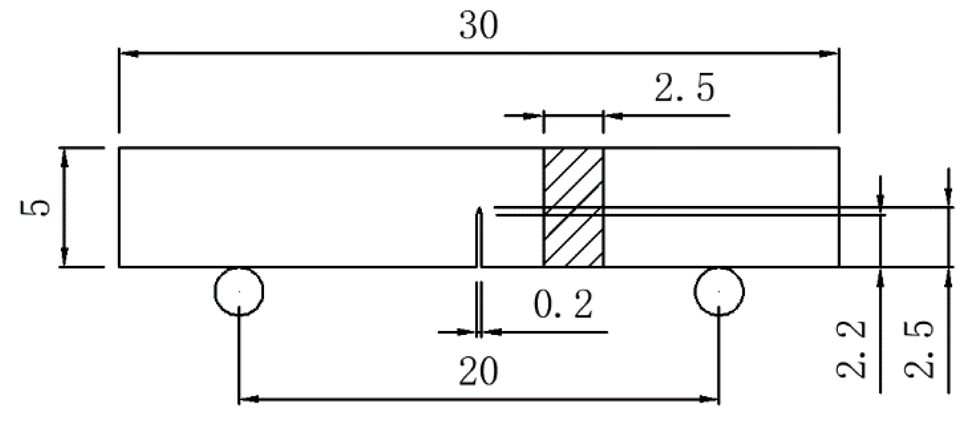
2. Materials and Methods

An ingot with a nominal composition of Ti-43Al-2Cr-1.5Mn-0.1Y alloy (at.%) was prepared using the water-cooled copper crucible vacuum induction melting technique. In order to eliminate the porosity left from the casting process, the ingot was hot isostatically pressed at 1250 °C/200 MPa for 4 h, followed by furnace cooling to room temperature. The chemical composition of the alloy was examined by X-ray fluorescence spectrometry (XRF), indicating that the actual composition of the alloy is Ti − (43.2 ± 0.18)Al − (1.89 ± 0.04)Cr − (1.53 ± 0.06)Mn − (0.11 ± 0.02)Y. A cylindrical billet, with a dimension of Φ100 mm × 150 mm, was cut from the ingot and coated with a refractory antioxidant coating. In order to avoid cracking during hot deformation, the billet was canned using 304 stainless steel. The billet was subjected to one-step forging to a height reduction of about 80% at 1200 °C, with a deformation rate of 1 mm/s. In order to eliminate internal stress, the forged billet was annealed at 900 °C for 30 h, followed by furnace cooling to room temperature. Then, the stainless steel canning was removed using the lathe. Finally, a crack-free forged pancake was obtained.
All the specimens for the microstructure observation and property testing were cut from the ingot and the forged pancake using the electro-discharge machining method. For the forged pancake, the sampling location was the core region of the pancake. Three point bending tests were performed using the universal testing machine. The fracture toughness test was based on ASTM E399, and each material was tested three times. The schematic diagram of the specimen for three point bending testing is shown in Figure 1. The pre-crack, with a length of 0.3 mm, was prepared. The bending specimens were mechanically grinded and polished in order to avoid a negative impact on the crack propagation. The microstructure and crack propagation behavior were observed by scanning electron microscopy (SEM) in back-scattered electron mode (BSE).

3. Results

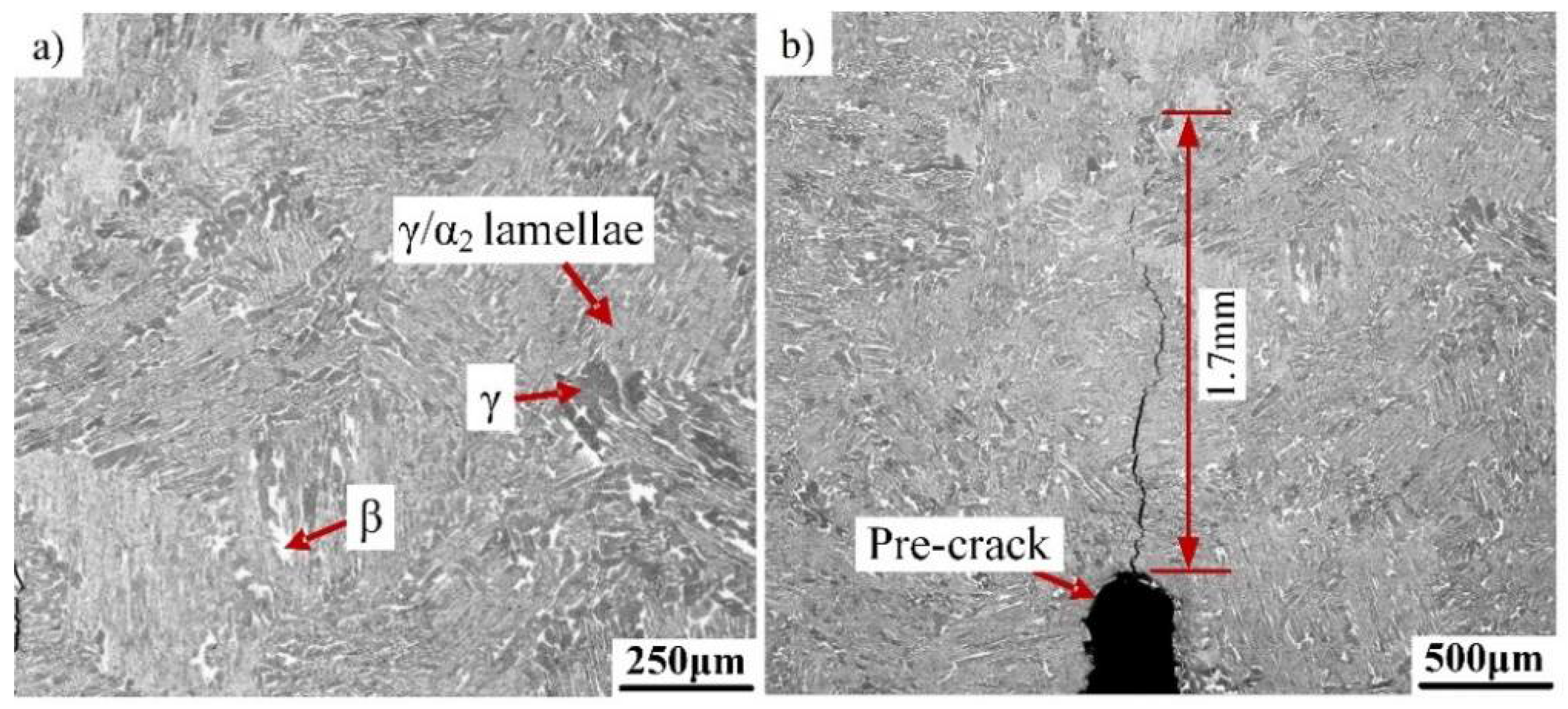
3.1. Initial Microstructure of the Ti-43Al-2Cr-1.5Mn-0.1Y Ingot

The as-cast microstructure of the Ti-43Al-2Cr-1.5Mn-0.1Y alloy is shown in Figure 2a. It can be seen that the alloy is composed of the γ/α2 lamellae, β0 phase (white) and a massive γ phase (black), as indicated by red arrows, which is different from conventional TiAl alloys. Coarse γ/α2 lamellaes with a colony size of 250 ± 50 μm are still the main feature of the microstructure. There are some β0 phases (30 ± 15 μm) that were associated with massive γ phases (60 ± 30 μm) and these were mainly precipitated at the boundary of the γ/α2 lamellar colonies. Moreover, it has been reported that the volume fraction of the β0 phase depends closely on the content of the β stablizers (Cr and Mn elements) [7]. Thus, a small amount of the β0 phase and massive γ phase also appeared inside the γ/α2 lamellaes due to the high content of the β0 phase, as shown in Figure 2a. Considering that different phases exhibit different contrast, the area of various microstructure with different contrast were measured using image analysis software. The approximate volume fraction of the β0, γ, and γ/α2 colonies are about 4.2%, 10%, and 85.8%, respectively. The precipitation of β0 phase is conducive to microstructure refinement [6]. In order to study the crack propagation behavior, single-edge notched bend specimens were adopted. A pre-crack was prepared before three-point bend testing. The whole crack propagation pathway was examined after bend testing, as shown in Figure 2b. It can be seen that only one main crack was formed and propagated. The total length of the crack was about 1.7 mm.

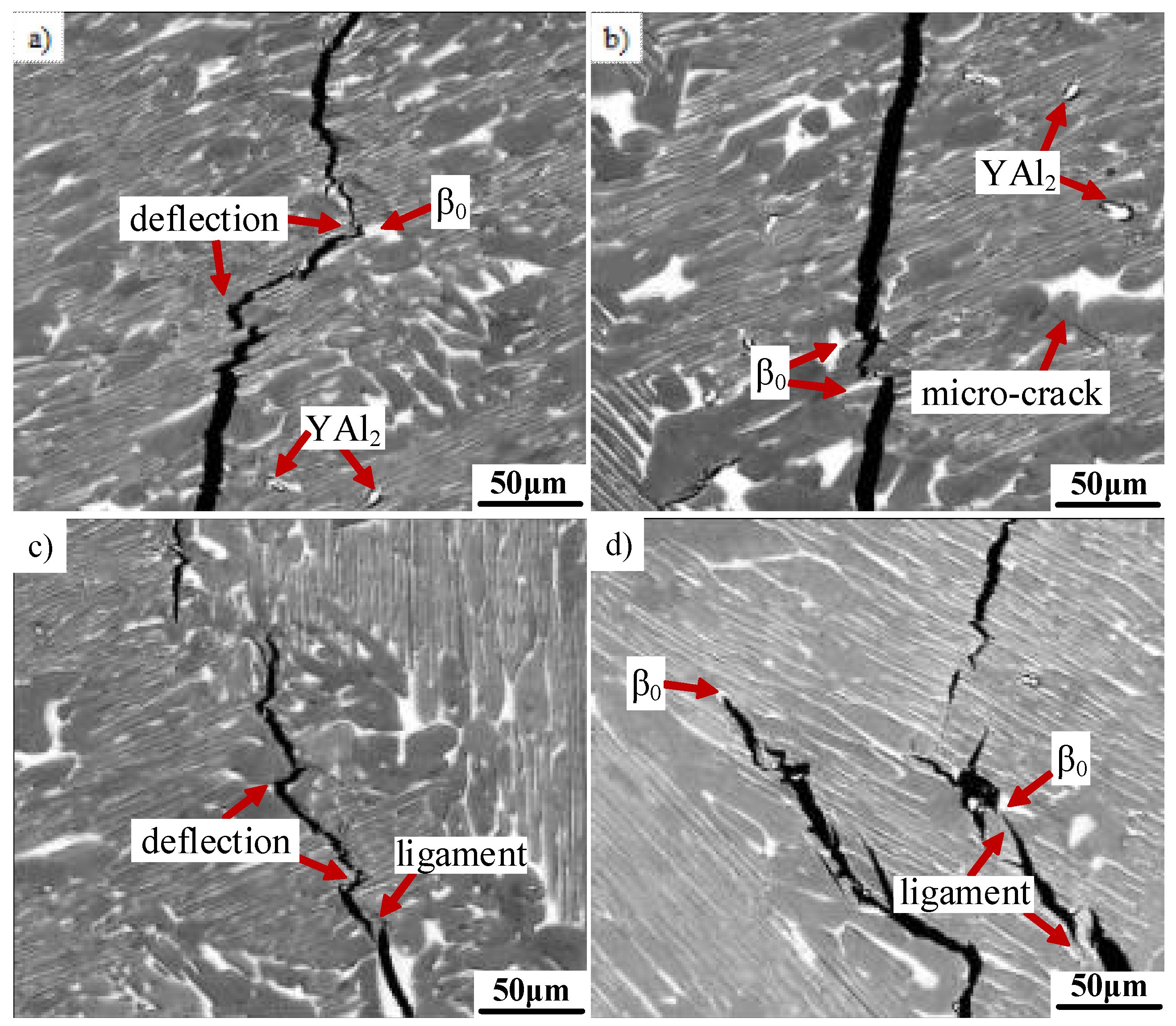
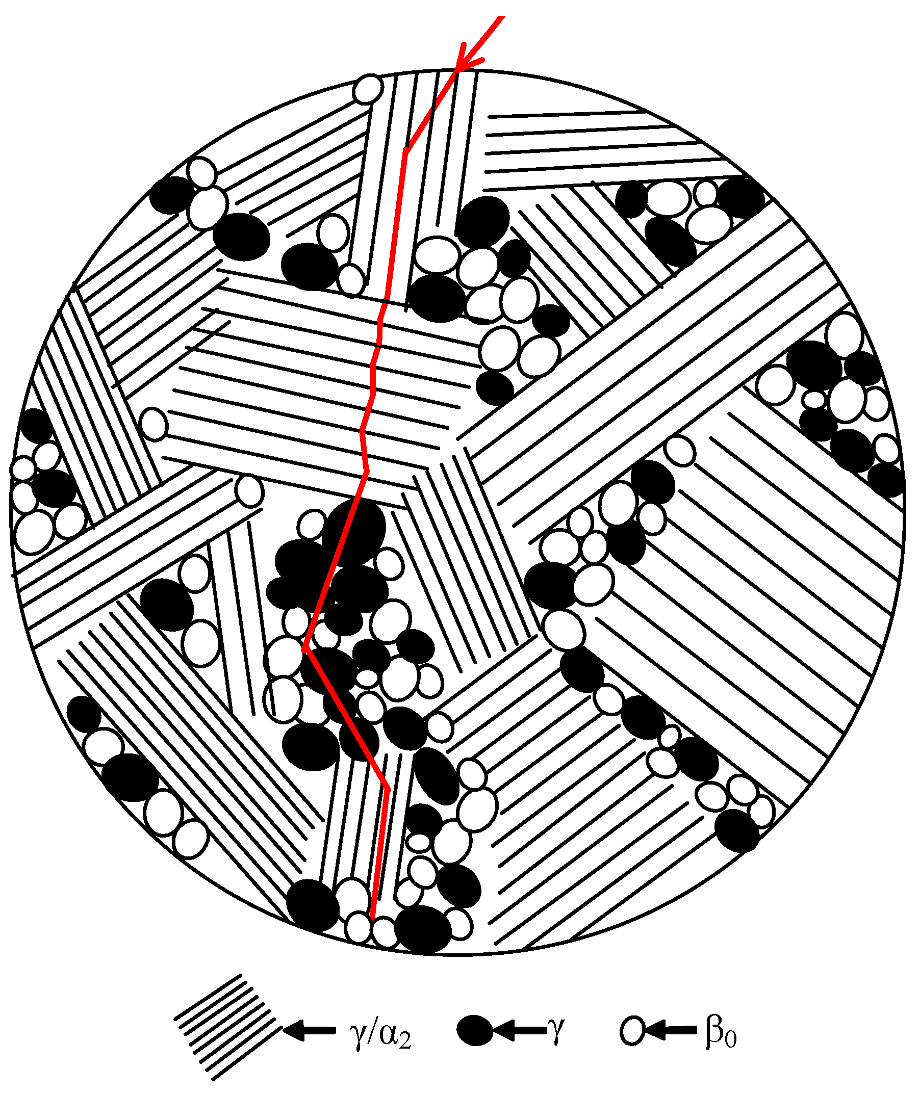
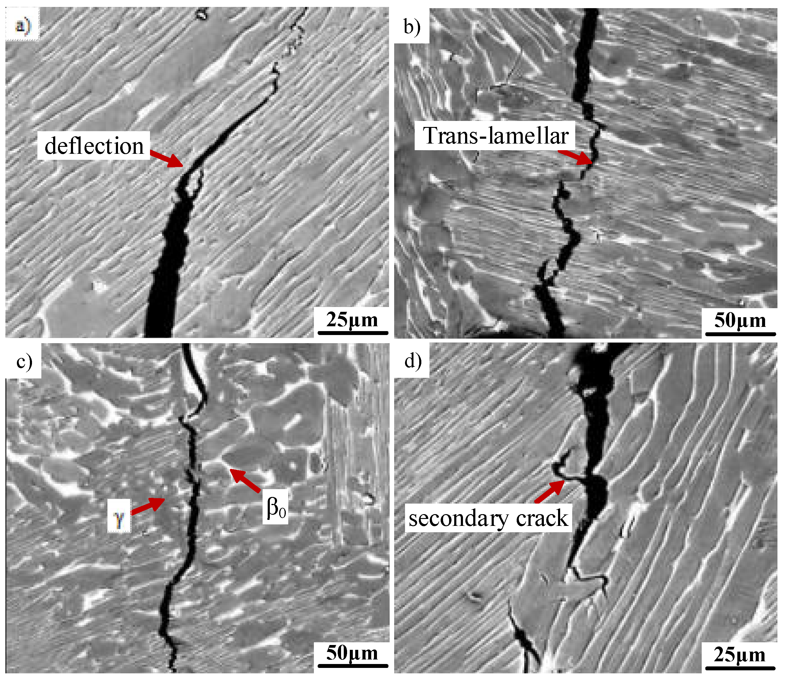
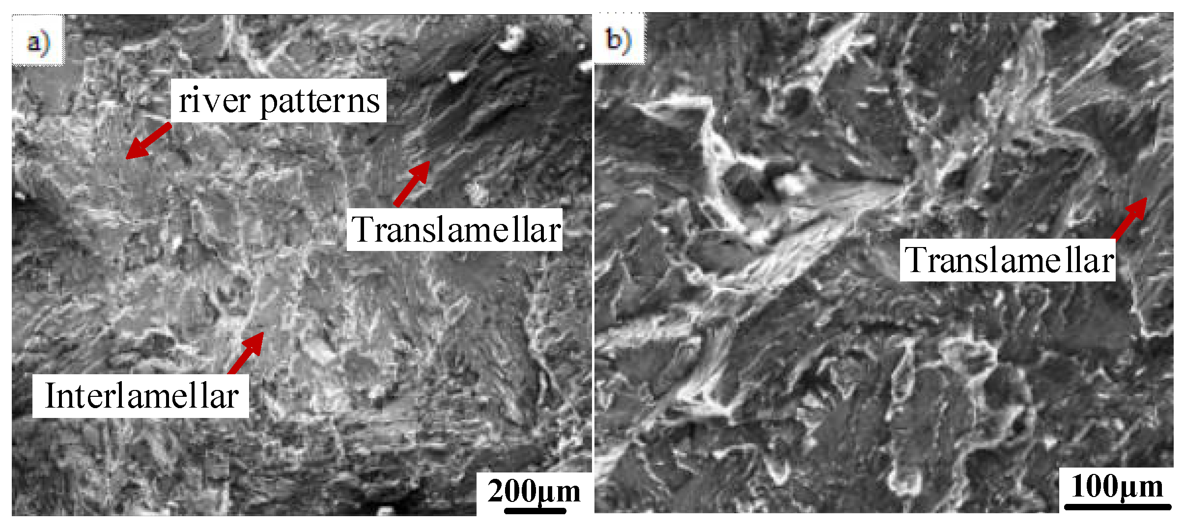
3.2. Crack Propagation Behavior in the Coarse Lamellar Microstructure

High magnification images of the crack propagation path in the coarse lamellar microstructure were obtained by SEM examination, as shown in Figure 3. It can be seen that the crack propagation pathway is not straight, but is a zigzag, and this depends largely on the microstructure features, especially the γ/α2 lamellar orientation. The interlamellar spacing is about 3 ± 2 μm. The initial crack may randomly propagate by the translamellar or inter-lamellar mode in complex stress conditions, owing to the existence of a pre-crack. However, a subsequent crack propagation direction was closely related to the γ/α2 lamellar orientation and the lamellar colony size. When the angle (θ) between the crack and the lamellar boundary is lower than 45°, it is very hard for the crack to across coarse lamellar colonies due to the existence of large numbers of γ/α2 phase boundaries. Thus, the crack tends to change direction and propagate along γ/α2 lamellae. Thus, the propagation mode changed from translamellar to interlamellar, as shown in Figure 3a. When the angle θ is close to 90°, the crack propagation direction is extremely difficult to change. The crack continued to propagate by translamellar mode, as shown in Figure 3b. As mentioned above, a fine grain β0 phase and a massive γ phase generally appeared at the boundaries of the γ/α2 lamellar colonies. Fine grains have weaker resistance to crack propagation than the coarse lamellar microstructure [11]. Thus, it can be seen from Figure 3c that the crack generally propagates straight through the β0/γ duplex. In addition, the crack propagation direction would not be significantly impacted if the size of the γ/α2 lamellar colony is small. It is also unable to provide enough resistance for the crack propagation. Figure 3d shows the presence of secondary cracks. Secondary cracks are generally initiated at the β0/γ duplex region, which should be attributed to the inhomogeneous deformation between β0 and γ phases, owing to the phase hardness difference.
The introduction of the β0 phase is the typical trait of the β-solidifying TiAl alloy. The β0 phase exhibits higher hardness compared to the γ and α2 phases, which would affect the crack propagation. Thus, the effect of the β0 phase on the crack propagation path was also studied in detail. As we can see in Figure 4a, the main crack propagated initially by the translamellar mode. Then the crack changed direction and propagated along the γ/α2 lamellar interface, as indicated by red arrows. This is consistent with the above observation. In particular, it can be seen that the crack propagation direction changed again at the β0 phase region. A similar phenomenon can also be observed in Figure 4b,c. This suggests that the crack propagation direction can be changed by the β0 phase, which should contribute to the high hardness of the β0 phase. It can be seen from Figure 4b that some micro-cracks appeared at the β0/γ duplex region, which may have formed due to initial casting defects or the stress concentration. It should be noted that the crack propagation direction is not changed by micro-cracks, which was identified by Yokoshima et al. [16]. Furthermore, the feature of crack tips was observed. As shown in Figure 4d, the crack tip tends to propagate within the γ/α2 lamellar colony, but often stops at the β0 phase region or the β0/γ phase interface, as indicated by red arrows. This is because the β0 phase, which has higher hardness can consume more energy in order to hinder crack propagation. In addition, some shear ligaments can be observed, as illustrated in Figure 4c,d, which generally formed between the mismatched crack planes [17,18]. The ligaments are generally formed in the γ phase region. Previous studies have confirmed that the hardness of the γ phase is generally lower than that of β0 and α2 phases [12]. The compatible deformation among γ, β0 and α2 phases was inhomogeneous during the three-point bending test, which leads to stress concentration. The γ phase, with low hardness, inevitably becomes the initiation site of shear ligaments. The formation of shear ligament is conducive to the enhancement of crack propagation resistance. Moreover, a small number of particles with white contrast can be observed, as indicated by the red arrow. EDS shows that the particles include YAl2. A similar phenomenon was also confirmed in previous studies concerning Y-containing TiAl alloys [19,20]. As is known, the Y atom has a stronger affinity to O atom in comparison with Al atom and Ti atom [21]. However, the smelting process was conducted in a high vacuum. Thus, Y is apt to form YAl2 rather than Y2O3 phase in TiAl alloys, which is randomly distributed in the microstructure. It should be noted that Y2O3 phase may also exist in the microstructure due to the strong affinity between Y and O atoms. No Y2O3 phase was detected in this paper, which may be attributed to its low content. The size of the particles enriched in Y is about 10 ± 5 μm. Y element can effectively refine the lamellar colony size and lamellar spacing of TiAl alloys, thereby affecting the crack propagation behavior. However, YAl2 particle itself have no significant influence on the crack propagation on the basis of existing experimental data (Figure 3 and Figure 4). The detailed study will be conducted in the future.
In order to further identify the fracture mechanism of the alloy, the fracture surface of the bending specimen of the as-cast TiAl alloy was observed. As shown in Figure 5, the fracture surface is characterized by brittle features. Nearly no plastic deformation can be observed. It can be seen from Figure 5a that some cleavage plane with river patterns occurred, as indicated by the red arrow. Moreover, as shown in Figure 5a,b, some broken lamellaes can be clearly observed, which is a typical feature of a translamellar fracture. Smooth surfaces formed by the crack propagation along the γ/α2 lamellae can also be found, which is called an interlamellar fracture. Thus, it is known that translamellar and interlamellar modes are the main fracture mechanisms.

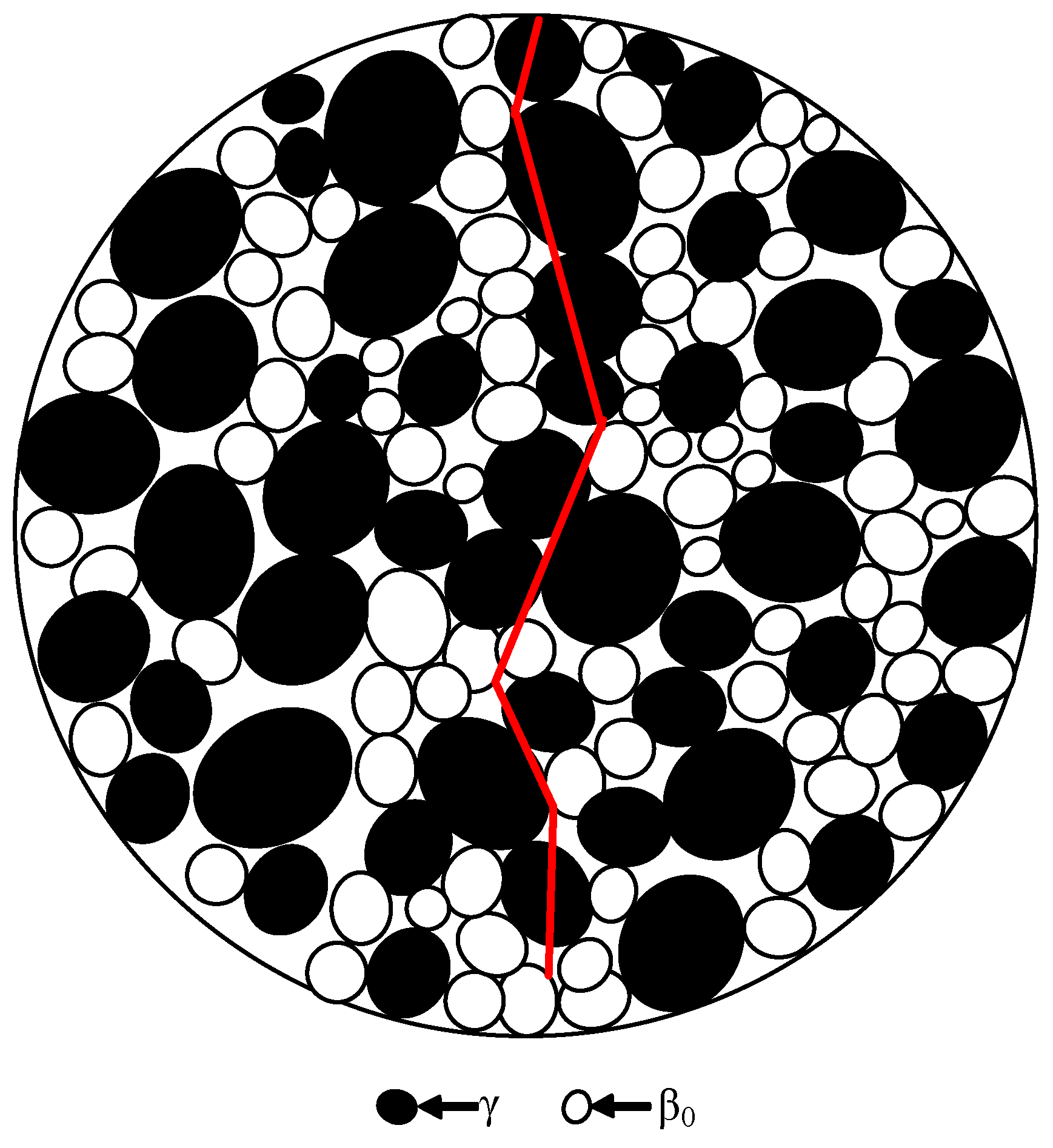
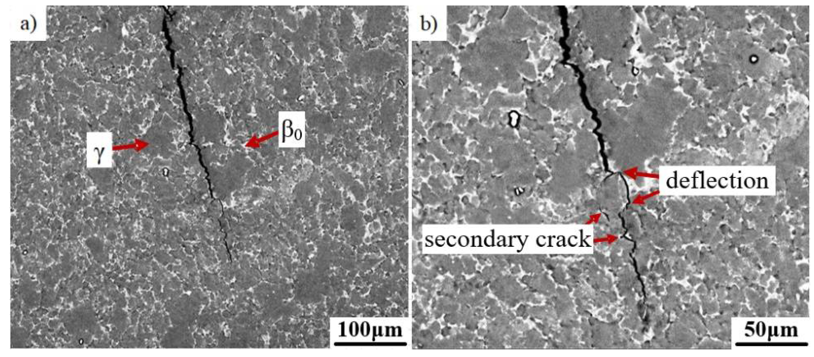
3.3. Crack Propagation Behavior in the Fine (γ+β0) Microstructure

To further study the crack propagation behavior of the fine-grained microstructure, coarse γ/α2 lamellae should be eliminated. As is known, thermomechanical treatment is an efficient way to refine the grain size. Here, the Ti-43Al-2Cr-1.5Mn-0.1Y ingot was deformed by one-step forging with a total engineering strain of 80%. As shown in Figure 6a, the microstructure of the deformed alloy is mainly composed of fine γ grains (30 ± 15 μm) and a white β0 phase (5 ± 2 μm). The statistics indicate that the volume fractions of the γ and β0 phases are about 77% and 23%, respectively. Nearly no residual γ/α2 colonies can be identified. It suggests that initial coarse γ/α2 lamellar colonies have been decomposed into fine grains completely during one-step forging. Ordered α2 and β0 phases transform to disordered α and β phases at a forging temperature of 1200 °C. Thus, the transition of L(γ/α) + β→γ + β→γ + β0 in the β-solidifying TiAl alloy occurred during forging, leading to the decomposition of γ/α2 lamellar colonies, which has been reported in the literature [22,23]. The crack propagation path can be clearly identified at a higher magnification, as shown in Figure 6b. It can be seen that the crack propagated through the β0/γ duplex region in a relatively straight line. Only a small fluctuation occurred at the γ/β0 phase interface. This is inconsistent with the crack propagation path in the as-cast microstructure with a coarse γ/α2 lamellar colony and β0/γ duplex phases. This indicates that as-forged fine grains would not significantly change the crack propagation. Small sized grains have difficulty in hindering crack propagation. The crack can bypass the hard phase easily. Thus, the crack propagation direction mainly changes at the γ/β0 phase interface due to the incompatible deformation between the γ and β0 phases. In addition, two secondary cracks can also be identified as indicated by red arrows. One crack generated at the β0 phase region is very short due to the resistance effect of the hard β0 phase.
The fracture mechanism in the fine-grained microstructure was also studied. The fracture surface of the fine-grained TiAl alloy is shown in Figure 7. The surface exhibits a typical brittle fracture feature. A large number of transgranular fractures occurred. The cleavage planes with river patterns can be identified as indicated by the red arrows in Figure 7b. The microstructure of the deformed alloy contains high volume fraction of the massive γ phase and some β0 phases. The crack tends to propagate across the γ phase with low hardness, leading to transgranular fracture. Thus, the transgranular mode is the main fracture mechanism in the fine-grained microstructure.

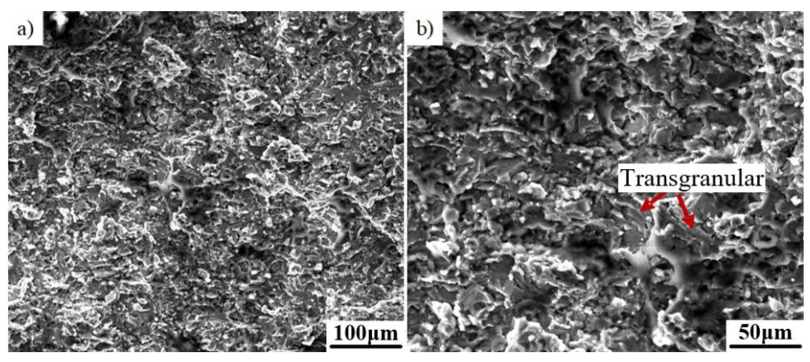
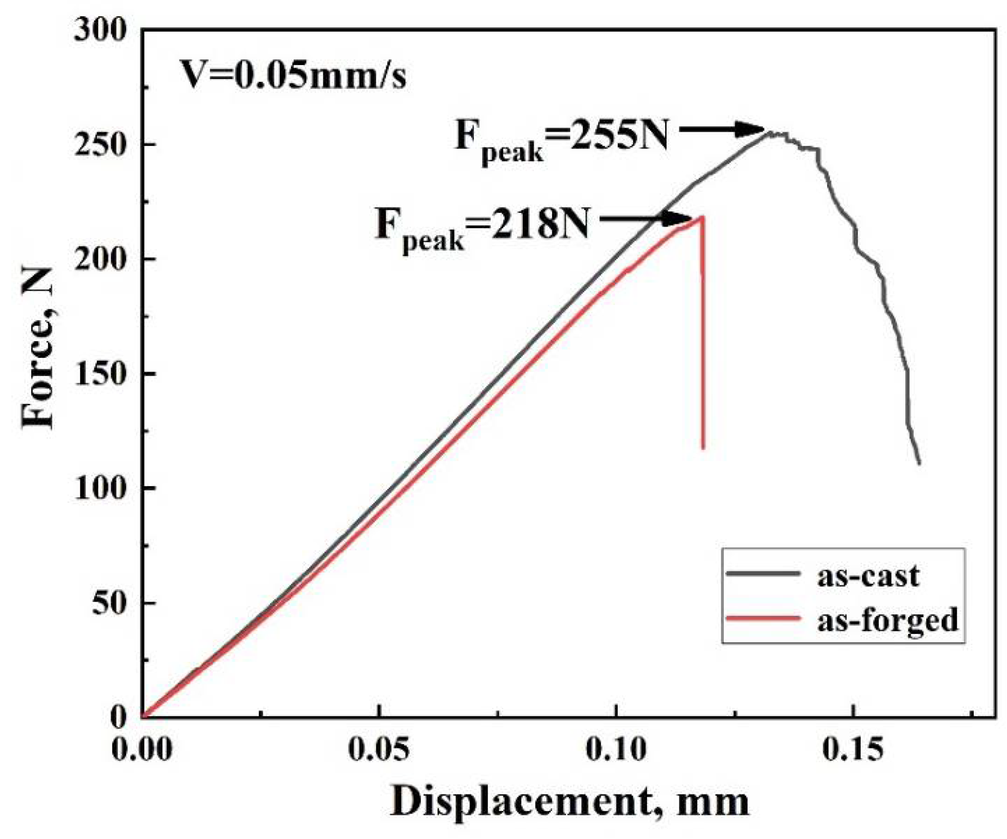
3.4. Fracture Toughness of the β-Solidifying TiAl Alloy with Different Microstructure

To further compare the effect of different microstructures on facture toughness, load-displacement curves of the Ti-43Al-2Cr-1.5Mn-0.1Y alloy in as-cast and as-forged conditions were obtained electronically during three-point bending tests. As shown in Figure 8, the maximum load of the as-cast and as-forged alloys are 255 N and 218 N, respectively. According to ASTM E399 standard, the fracture toughness (K1c) values can be obtained by following equations [24], where FQ is the maximum load, S is the span, B is the specimen thickness, W is the specimen width, a is the crack length.
K I C = ( F Q S / B W 3 / 2 ) × f ( a / W )
f ( a / W ) = 3 ( a / W ) 1 / 2 × 1.99 ( a / W ) ( 1 a / W ) [ 2.15 3.93 ( a / W ) + 2.7 ( a / W ) 2 ] 2 ( 1 + 2 a / W ) ( 1 a / W ) 3 / 2
Based on Equations (1) and (2), the fracture toughness value of the as-cast alloy is 15.4 ± 0.5 MPa∙m1/2, which is higher than that of the as-forged alloy (13.2 ± 0.3 MPa∙m1/2). This indicates that a coarse microstructure in the as-cast alloy can more effectively hinder crack propagation, as compared to fine grains in the as-forged alloy. A large number of γ/α2 lamellar boundaries play an important role in the improvement of the fracture toughness of the alloy.

3.5. Crack Propagation Model of the β-Solidifying TiAl Alloy

In order to express the crack propagation mechanism more clearly, two typical crack propagation models were constructed based on the above experiments. Figure 9 shows the crack propagation model in the microstructure containing γ/α2 lamellae, a hard β0 phase and a massive γ phase. In this figure, the β0 phase and γ phase exhibit white contrast and black contrast. The crack generally initiates at the phase boundaries due to the low binding force between the γ and α2 phases. Then when the angle between the propagation direction and γ/α2 lamellar boundaries is lower than 45°, the crack tends to propagate along the lamellar boundaries. When the propagation direction is nearly perpendicular to the lamellar boundaries, the crack can only traverse across the γ/α2 lamellae because the crack has difficulty bypassing coarse lamellar colonies. A great deal of γ/α2 phase boundaries are considered to contribute significantly to the fracture resistance of the alloy. Massive β0/γ phases are a typical feature of β-solidifying TiAl alloys, which have a certain impact on the crack propagation behavior. The crack is generally across the β0/γ region in the transgranular mode. Moreover, it should be noted that the crack propagation direction would be changed by a hard β0 phase. Previous studies have shown that the fracture stress of the alloy in the β-quenched condition is generally higher than 1600 MPa, indicating that the β0 phase has good toughness [25]. Thus, the β0 phase can consume the crack propagation energy effectively. The crack tends to stop in the β0 phase region.
The crack propagation model for the β-solidifying TiAl alloy with a fine γ+β0 microstructure was also constructed, as shown in Figure 10. The γ and β0 phases generally exhibit a fine grain size, which has weak inhibition effects on the crack propagation. Thus transgranular failure is the main mode in the fine-grained microstructure. The crack is relatively straight. Nevertheless, the β0 phase, with high hardness, also has a certain influence on the crack propagation path.

4. Conclusions

In this paper, a typical β-solidifying TiAl alloy was fabricated by the ingot metallurgy route. The crack propagation behavior of the β-solidifying TiAl alloy with different microstructures was investigated in detail. The main conclusions are summarized as follows:
(1) A β-solidifying TiAl alloy with a nominal composition of Ti-43Al-2Cr-1.5Mn-0.2Y alloy was fabricated. The initial as-cast microstructure is mainly composed of coarse γ/α2 lamellae, β0 phase and massive γ phase. The coarse γ/α2 lamellaes were decomposed into fine γ and β0 grains during one-step hot deformation.
(2) Hard β0 phase can consume more propagation energy, thereby changing the crack propagation direction. The crack tends to stop at the β0 phase region.
(3) The crack propagation direction is closely related to the lamellar orientation. When the angle between the crack and the lamellar boundary is small, the crack tends to propagate along the γ/α2 lamellae. When the angle is close to 90°, the crack tends to propagate by the translamellar mode.
(4) The facture toughness of the TiAl alloy with a coarse microstructure is better than that of the alloy with fine grains owing to the high resistance of coarse γ/α2 lamellar boundaries in the crack’s growth. Some shear ligaments were formed in the γ/α2 lamellar microstructure, which is also conducive to enhancing crack propagation resistance.

Author Contributions

Conceptualization, N.C.; methodology, N.C.; software, Q.L.; validation, S.Z.; formal analysis, N.C.; investigation, S.Z.; resources, N.C.; data curation, Q.L.; writing—original draft preparation, S.Z.; writing—review and editing, N.C., W.S.; visualization, S.Z.; supervision, N.C.; project administration, N.C.; funding acquisition, N.C. All authors have read and agreed to the published version of the manuscript.

Funding

This research was funded by the Shandong Province Key Research and Development Program (2019GGX102045) and the National Natural Science Foundation of China (51704174).

Institutional Review Board Statement

Not applicable.

Informed Consent Statement

Not applicable.

Data Availability Statement

Not applicable.

Conflicts of Interest

The authors declare no conflict of interest. The funders had no role in the design of the study; in the collection, analyses, or interpretation of data; in the writing of the manuscript, or in the decision to publish the results.

References

  1. Clemens, H.; Mayer, S. Advanced Intermetallic TiAl Alloys. Mater. Sci. Forum 2017, 879, 113–118. [Google Scholar] [CrossRef]
  2. Janschek, P. Wrought TiAl Blades. Mater. Today 2015, 2, 92–97. [Google Scholar] [CrossRef]
  3. Appel, F.; Paul, J.D.H.; Oehring, M. Gamma Titanium Aluminide Alloys: Science and Technology; John Wiley & Sons: Weinheim, Germany, 2011. [Google Scholar]
  4. Appel, F.; Clemens, H.; Fischer, F.D. Modeling concepts for intermetallic titanium aluminides. Prog. Mater. Sci. 2016, 81, 55–124. [Google Scholar] [CrossRef]
  5. Clemens, H.; Wallgram, W.; Kremmer, S.; Güther, V.; Otto, A.; Bartels, A. Design of novel β-solidifying TiAl alloys with adjustable β/B2-phase fraction and excellent hot-workability. Adv. Eng. Mater. 2008, 10, 707–713. [Google Scholar] [CrossRef]
  6. Schwaighofer, E.; Rashkova, B.; Clemens, H.; Stark, A.; Mayer, S. Effect of carbon addition on solidification behavior, phase evolution and creep properties of an intermetallic β-stabilized γ-TiAl based alloy. Intermetallics 2014, 46, 173–184. [Google Scholar] [CrossRef] [Green Version]
  7. Kong, F.; Cui, N.; Chen, Y.; Wang, X. A novel composition design method for beta-gamma TiAl alloys with excellent hot workability. Metall. Mater. Trans. A 2018, 49, 5574–5584. [Google Scholar] [CrossRef]
  8. Zhang, K.; Hu, R.; Li, J.; Yang, J.; Gao, Z. Grain Refinement of 1 at.% Ta-containing cast TiAl-based alloy by cyclic air-cooling heat treatment. Mater. Lett. 2020, 274, 127940. [Google Scholar] [CrossRef]
  9. Yim, S.; Bian, H.; Aoyagi, K.; Chiba, A. Effect of multi-stage heat treatment on mechanical properties and microstructure transformation of Ti–48Al–2Cr–2Nb alloy. Mater. Sci. Eng. A 2021, 816, 141321. [Google Scholar] [CrossRef]
  10. Takeyama, M.; Kobayashi, S. Physical metallurgy for wrought gamma titanium aluminides microstructure control through phase transformations. Intermetallics 2005, 13, 993–999. [Google Scholar] [CrossRef]
  11. Clemens, H.; Mayer, S. Design, processing, microstructure, properties, and applications of advanced intermetallic TiAl alloys. Adv. Eng. Mater. 2013, 15, 191–215. [Google Scholar] [CrossRef]
  12. Schloffer, M.; Iqbal, F.; Gabrisch, H.; Schwaighofer, E.; Schimansky, F.P.; Mayer, S.; Stark, A.; Lippmann, T.; Göken, M.; Pyczak, F.; et al. Microstructure development and hardness of a powder metallurgical multi phase γ-TiAl based alloy. Intermetallics 2012, 22, 231–240. [Google Scholar] [CrossRef] [Green Version]
  13. Schloffer, M.; Rashkova, B.; Schöberl, T.; Schwaighofer, E.; Zhang, Z.; Clemens, H.; Mayer, S. Evolution of the ω0 phase in a β-stabilized multi-phase TiAl alloy and its effect on hardness. Acta Mater. 2014, 64, 241–252. [Google Scholar] [CrossRef]
  14. Kim, Y.W.; Kim, S.L. Advances in gammalloy materials–processes–application technology: Successes, dilemmas, and future in gammalloy materials–processes–application technology. JOM 2018, 5, 1–8. [Google Scholar] [CrossRef] [Green Version]
  15. Edwards, T.E.J. Recent progress in the high-cycle fatigue behaviour of gamma-TiAl alloys. Mater. Sci. Technol. 2018, 34, 1919–1939. [Google Scholar] [CrossRef] [Green Version]
  16. Yokoshima, S.; Yamaguchi, M. Fracture behavior and toughness of PST crystals of TiAl. Acta Mater. 1996, 44, 873–883. [Google Scholar] [CrossRef]
  17. Chan, K.S.; Kim, Y.W. Influence of microstructure on crack-tip micromechanics and fracture behaviors of a two-phase TiAl alloy. Metall. Trans. A 1992, 23, 1663–1677. [Google Scholar] [CrossRef]
  18. Wu, H.; Fan, G. An overview of tailoring strain delocalization for strength-ductility synergy. Prog. Mater. Sci. 2020, 113, 51. [Google Scholar] [CrossRef]
  19. Cui, N.; Wang, X.P.; Kong, F.T.; Chen, Y.Y.; Zhou, H.T. Microstructure and properties of a beta-solidifying TiAl-based alloy with different refiners. Rare Metals 2016, 35, 42–47. [Google Scholar] [CrossRef]
  20. Su, Y.; Kong, F.; Chen, Y.; Gao, N.; Zhang, D. Microstructure and mechanical properties of large size Ti-43Al-9V-0.2Y alloy pancake produced by pack-forging. Intermetallics 2013, 34, 29–34. [Google Scholar] [CrossRef]
  21. Kobayashi, Y.; Tsukihashi, F. Thermodynamics of yttrium and oxygen in molten Ti, Ti3Al, and TiAl. Metall. Mater. Trans. B 1998, 29, 1037–1042. [Google Scholar] [CrossRef]
  22. Cui, N.; Kong, F.; Wang, X.; Chen, Y.; Zhou, H. Microstructural evolution, hot workability, and mechanical properties of Ti–43Al–2Cr–2Mn–0.2Y alloy. Mater. Des. 2016, 89, 1020–1027. [Google Scholar] [CrossRef]
  23. Niu, H.Z.; Chen, Y.F.; Zhang, Y.S.; Lu, J.W.; Zhang, W.; Zhang, P.X. Phase transformation and dynamic recrystallization behavior of a β-solidifying γ-TiAl alloy and its wrought microstructure control. Mater. Des. 2016, 90, 196–203. [Google Scholar] [CrossRef]
  24. Wang, Y.; Ding, H.; Zhang, H.; Chen, R.; Guo, J.; Fu, H. Microstructures and fracture toughness of Ti–(43–48)Al–2Cr–2Nb prepared by electromagnetic cold crucible directional solidification. Mater. Des. 2014, 64, 153–159. [Google Scholar] [CrossRef]
  25. Kamat, S.V.; Gogia, A.K.; Banerjee, D. Effect of alloying elements and heat treatment on the fracture toughness of Ti–Al–Nb alloys. Acta Mater. 1998, 46, 239–251. [Google Scholar] [CrossRef]
Figure 1. A schematic diagram of specimens for three point bending testing (unit: mm).
Metals 11 01231 g001
Figure 2. The microstructure (a) and the crack appearance (b) of the initial as-cast Ti-43Al-2Cr-1.5Mn-0.1Y alloy.
Metals 11 01231 g002
Figure 3. The dependence of crack propagation on γ/α2 lamellar orientation. (a) deflection, (b) trans-lamellar crack, (c) γ/β0 region, (d) secondary crack.
Metals 11 01231 g003
Figure 4. The effect of the β0 phase on crack propagation in the as-cast TiAl alloy. (a) deflection, (b) YAl2, (c) deflection and ligament, (d) ligament.
Metals 11 01231 g004
Figure 5. The fracture surface of the as-cast TiAl alloy. (a) Interlamellar and translamellar frature, (b) translamellar frature.
Metals 11 01231 g005
Figure 6. The crack propagation behavior of the as-forged Ti-43Al-2Cr-1.5Mn-0.1Y alloy. (a) macro morphology, (b) secondary crack and deflection.
Metals 11 01231 g006
Figure 7. The fracture surface for the bending sample of the as-forged TiAl alloy. (a) macro morphology, (b) transgranular feature.
Metals 11 01231 g007
Figure 8. Load-displacement curves of the Ti-43Al-2Cr-1.5Mn-0.1Y alloy in different conditions.
Metals 11 01231 g008
Figure 9. The crack propagation model in the coarse lamellar microstructure.
Metals 11 01231 g009
Figure 10. The crack propagation model in the fine γ+β0 microstructure.
Metals 11 01231 g010
Publisher’s Note: MDPI stays neutral with regard to jurisdictional claims in published maps and institutional affiliations.

