3.2. Influence of Bonding Temperature on Microstructure of Joints
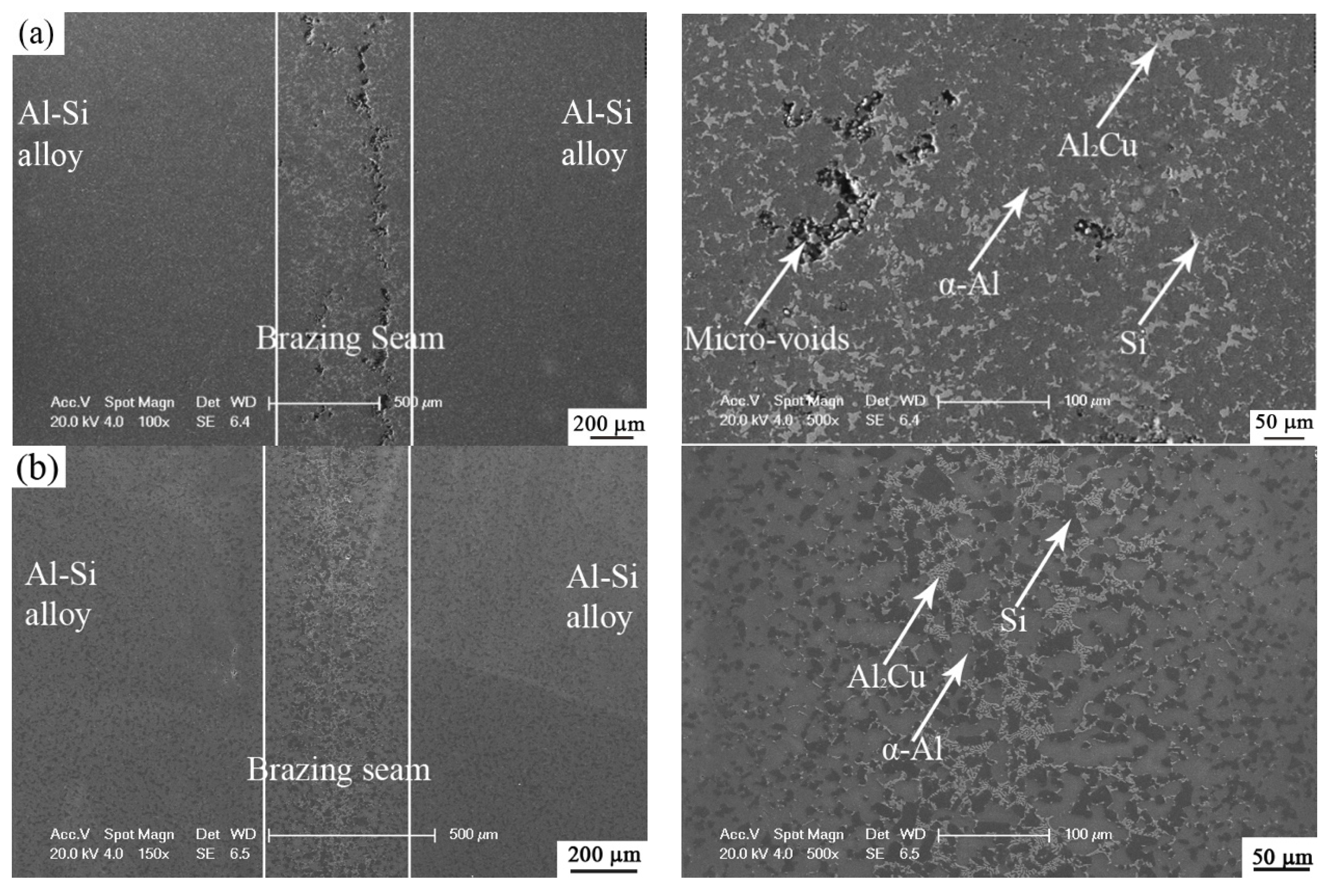
Figure 3 shows the microstructural evolution in the brazing seam at different bonding temperatures under a constant holding time of 10 min. The left column in
Figure 3 represents the macroscopic appearance, while the right column represents the magnified observation on the brazing seam. With the temperature increasing, the width of the brazing seam increased. When the brazing temperature was 535 °C, the width of the brazing seam is about 300 μm, as shown in
Figure 3a. Because the thickness of Cu foil was only 30 μm before brazing, the interaction between Al-25Si-4Cu-1Mg with Cu interlayer fully occurred through the transient liquid phase during the brazing process. In
Figure 3a, we can observe lots of white phases at the center of brazing joints, which were Al
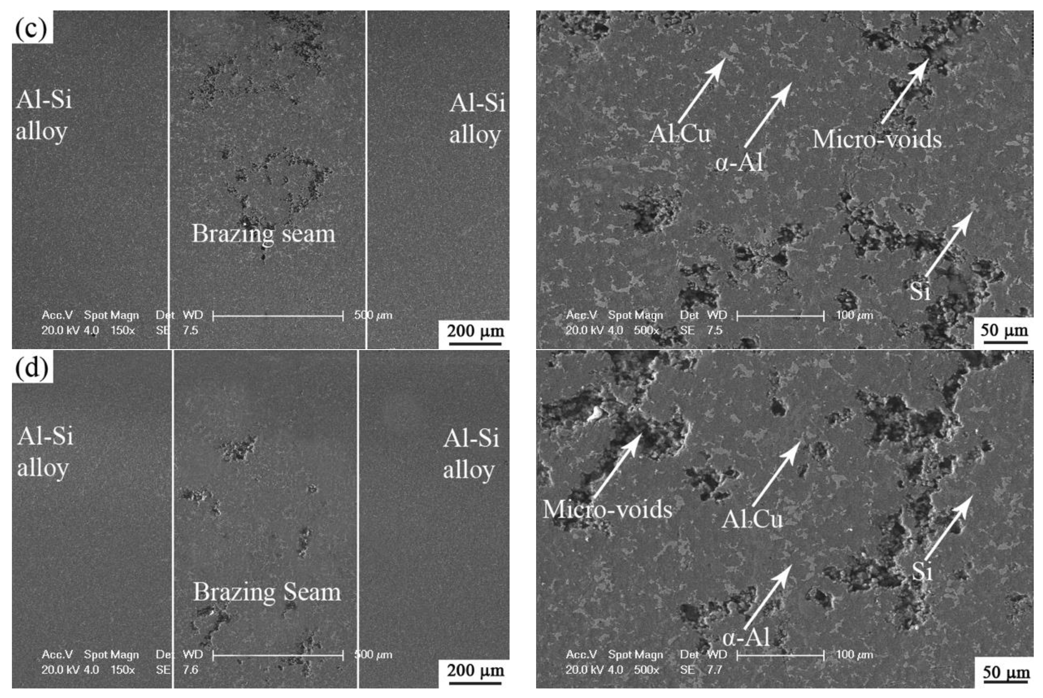
2Cu IMCs. On the other hand, there are many voids in the joint. When the temperature increased to 540 °C, as shown in
Figure 3b, the brazing seam was perfectly formed without any voids. The width of the brazing seam is about 450 μm. At the center of the brazing seam, white Al-Cu IMCs and coarsened gray Si particles are uniformly distributed in the Al matrix. With the temperature continuously increasing, the brazing seam continues to expand to about 700 μm. However, large numbers of voids were observed in the brazing seam, as shown in
Figure 3c,d. It can be seen that most of the voids were produced along the grain boundary of Al phases. Compared with
Figure 3a,b, the increasing brazing temperature obviously promoted the growth on the width of the brazing seam. Because the eutectic temperature between Al and Cu was 548 °C, the Cu intermediate layer and Al-based alloy would undergo the eutectic reaction even without the enrollment of Si phases, resulting in the obvious diffusion of Cu into the Al matrix and accordingly a large increase in the width of the brazing seam compared to low-temperature brazing. There are some defects such as voids in the brazing seam because when the Al-Cu eutectic temperature was reached, large amounts of eutectic liquid flowed along the grain boundary of α-Al, and part of the eutectic liquid was also in contact with the primary Si. When the brazing process began cooling, the eutectic liquid solidified into a hard and brittle Al-Cu intermetallic compound. Due to the difference in thermal expansion coefficients between Al and Si, residual stress was generated during solidification, resulting in the formation of voids. From the above experiments, the optimal brazing temperature should be in between the Al-Si-Cu ternary eutectic temperature (524 °C) and the Al-Cu eutectic temperature (548 °C).
Therefore, when the brazing temperature was 540 °C, the perfect brazing seam was produced without any defects or voids. The sample with a brazing temperature of 540 °C was furtherly analyzed. During diffusion bonding between Al-Si-Cu-Mg with Cu interlayer, Al atoms and Cu atoms were inter diffused into Cu interlayer and Al-Si alloy, respectively. The Al-Si-Cu ternary eutectic temperature is 522 °C from the ternary phase diagram of Al-Si-Cu [
19]. Therefore, after a short time, Al-Si-Cu eutectic composition was locally reached at the interface between the Al-Si base and Cu interlayer. Transient phases were produced with the ternary eutectic reaction:
where L represents the liquid phase. With more liquid phases produced, most of the residue Si would be precipitated during the brazing process.
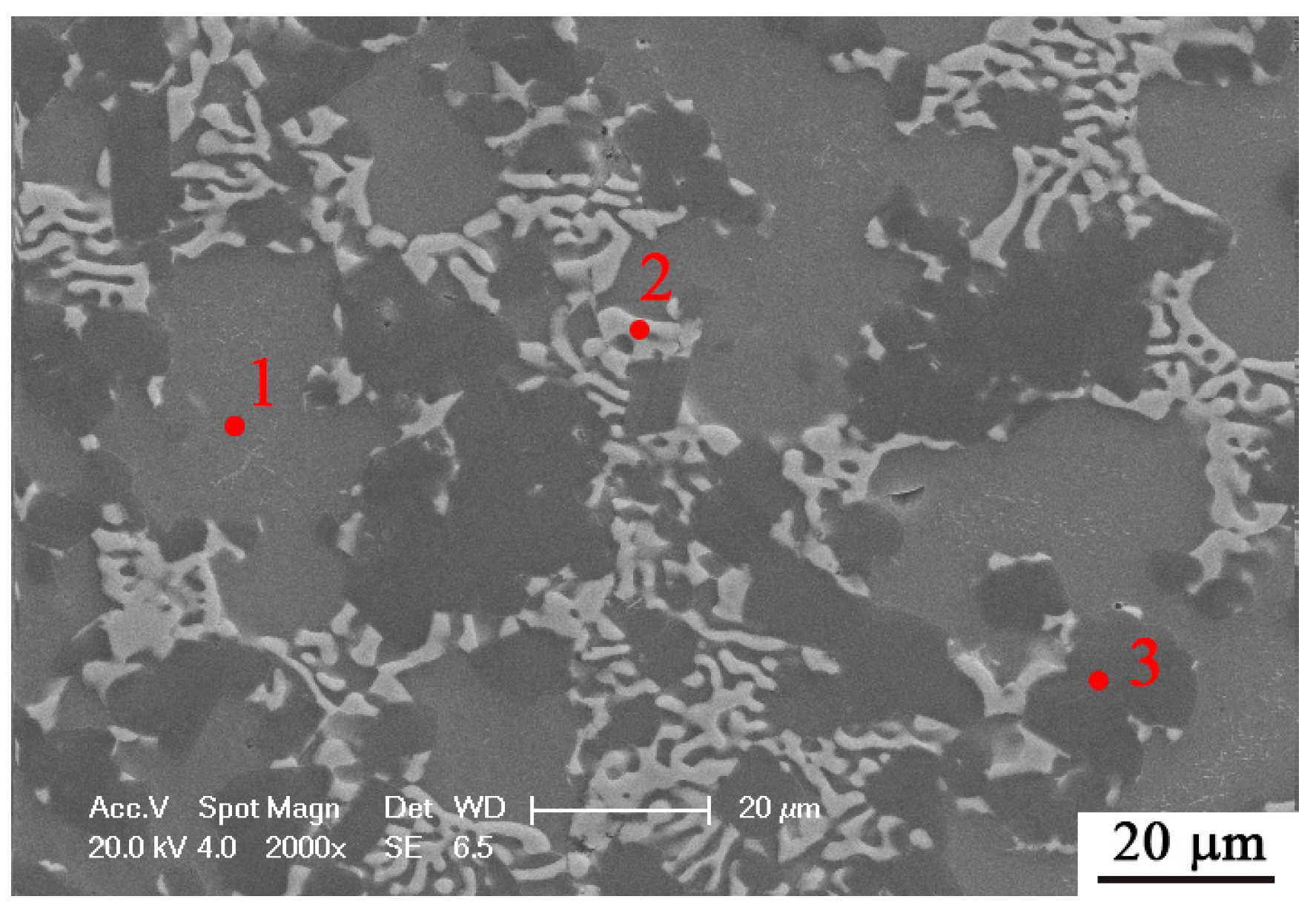
Figure 4 shows the interfacial microstructure in brazing joints under the brazing temperature of 540 °C for a holding time of 10 min.
Table 1 shows the results of the EDS spectrum analysis in
Figure 4. Spot 1 is a dark gray Al-based solid solution (α-Al). Al atoms in the base metal diffused into the center of the brazing seam under high temperature and pressure, which resulted in the formation of dark gray solid solution with Cu as a solute solution. The bright phase shown in spot 2 is an Al-Cu intermetallic compound. According to the results of the EDS analysis, the composition of the bright phase in the brazing seam is close to Al
2Cu intermetallic compound. Its appearance will usually reduce the plasticity and properties of joints, especially with a continuous layer of Al
2Cu. Under this parameter, coarsened Si particles were produced with the size reaching 20 μm, as marked with spot 3.
The experiments in this chapter illustrated the effect of brazing temperature on the micro-morphology of joints. According to the experimental results, the optimal temperature is 540 °C.
3.3. Influence of Holding Time on Microstructure of the Joints
The purpose of this section is to investigate the effect of holding time on the microstructural evolution in the joints. The brazing temperature was set at 540 °C. When the holding time was 5 min, lots of defects were produced in the center of the brazing seam. The reason for the defect is that the eutectic liquid phase cannot completely fill in the brazing seam because of the shorter holding time. Therefore,
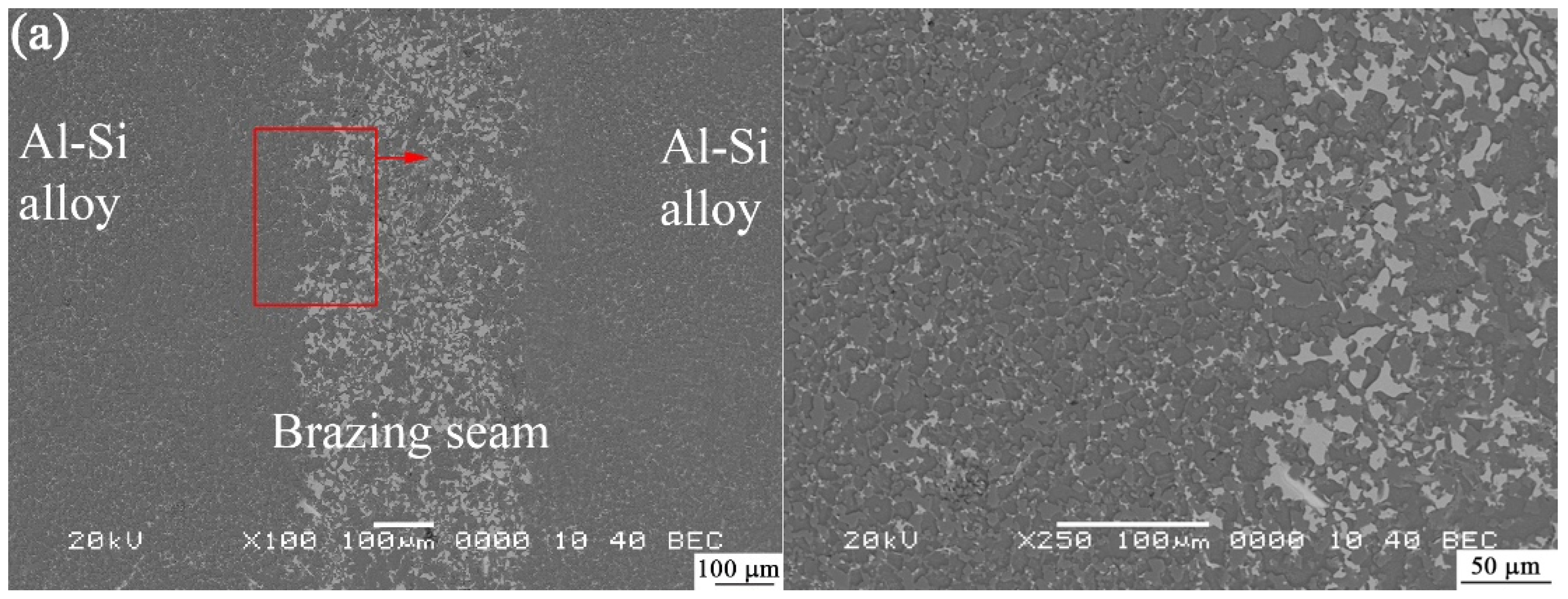
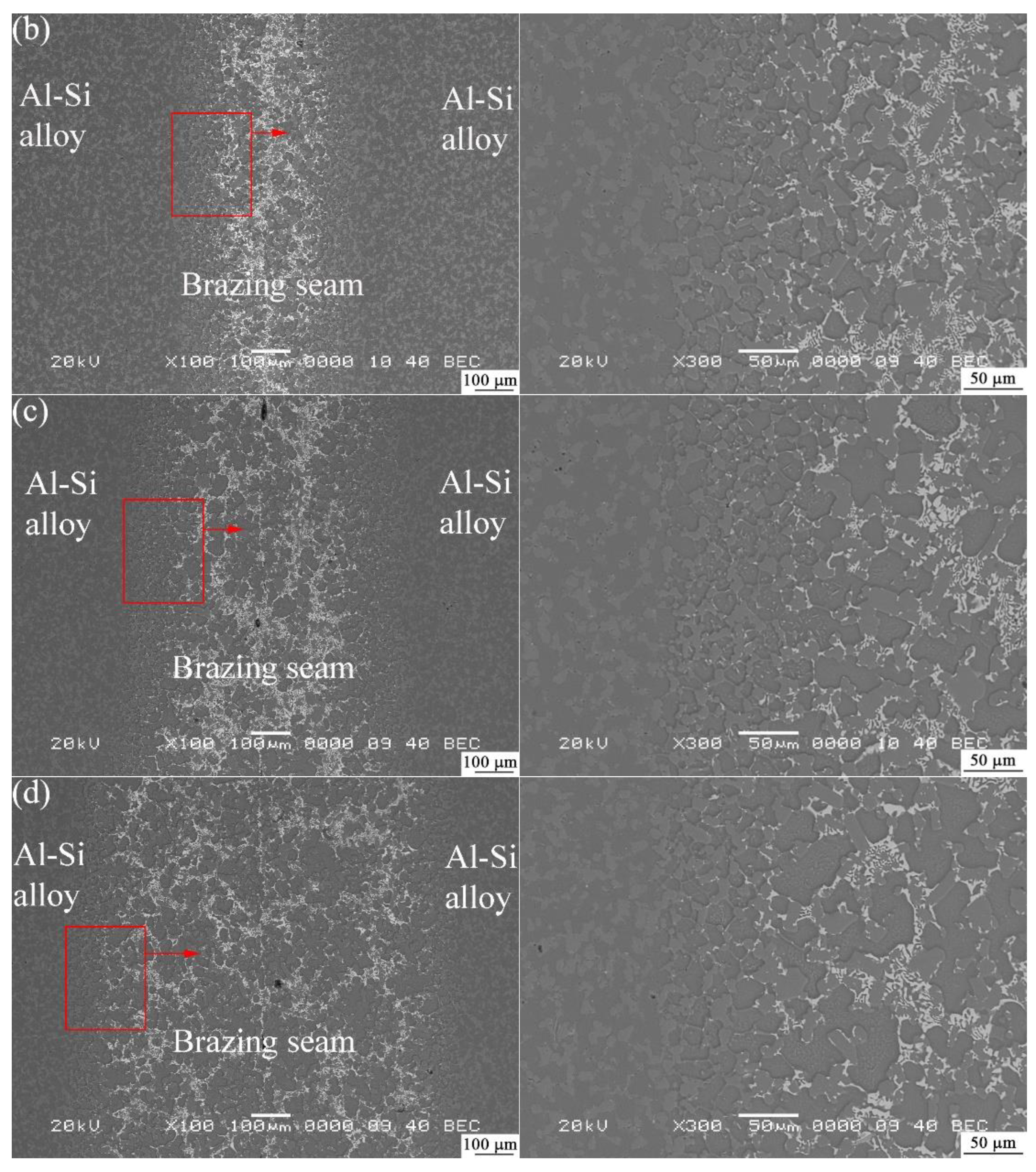
Figure 5 mainly shows the results with a holding time from 7.5 to 15 min. The right column represents the magnified structure on the red areas in the left column. It can be found that there is no void in the brazing seam and the joints are perfectly connected. When the holding time was 7.5 min, as shown in
Figure 5a, a brazing seam with a thickness of about 400 μm was produced at the interface. There was no observation on the residual Cu interlayer in the center of the brazing seam, and therefore the Cu interlayer was fully reacted with the Al base metal to produce Al-Si-Cu eutectic and Al
2Cu IMCs, which were mostly aggregated in the narrow brazing seam. White Al
2Cu phases were obviously observed in the brazing seam in
Figure 5a. In the Al-Si matrix, fine Si particles were uniformly distributed in Al phases, which was a typical spray-formed Al-Si microstructure. After the holding time was prolonged to 10 min, as shown in
Figure 5b, there was no obvious change to the width of the brazing seam, but the distribution of Al
2Cu was transformed into a network structure around Al-rich phases. Moreover, large amounts of Al-Cu compounds accumulated in the brazing seam, while a small amount of Al-Cu compound migrated along the grain boundary to the base metal. In the base metal, Si particles were slightly coarsened. At the interface between the brazing seam and base metal, it was interesting to find that more Si particles were segregated. With Cu diffusing into the Al-Si base metal, Cu and Al was reacted to produce Al
2Cu, and accordingly, Si atoms were segregated to produce clustered Si particles. With the holding time increased to 12.5 min, as shown in
Figure 5c, the thickness of the brazing seam increased to 550 μm. The Al-Cu compound at the center of the brazing seam was furtherly reduced. Similarly, more finely clustered Si particles were produced between the base metal and brazing seam. After the holding time was extended to 15 min, Cu was furtherly diffused into the Al-Si base metal, by which the thickness of the brazing seam reached 850 μm, as seen in
Figure 5d.
The formation of the Al-Cu compound is the diffusion of Cu atoms from the center of the brazing seam to the base metal [
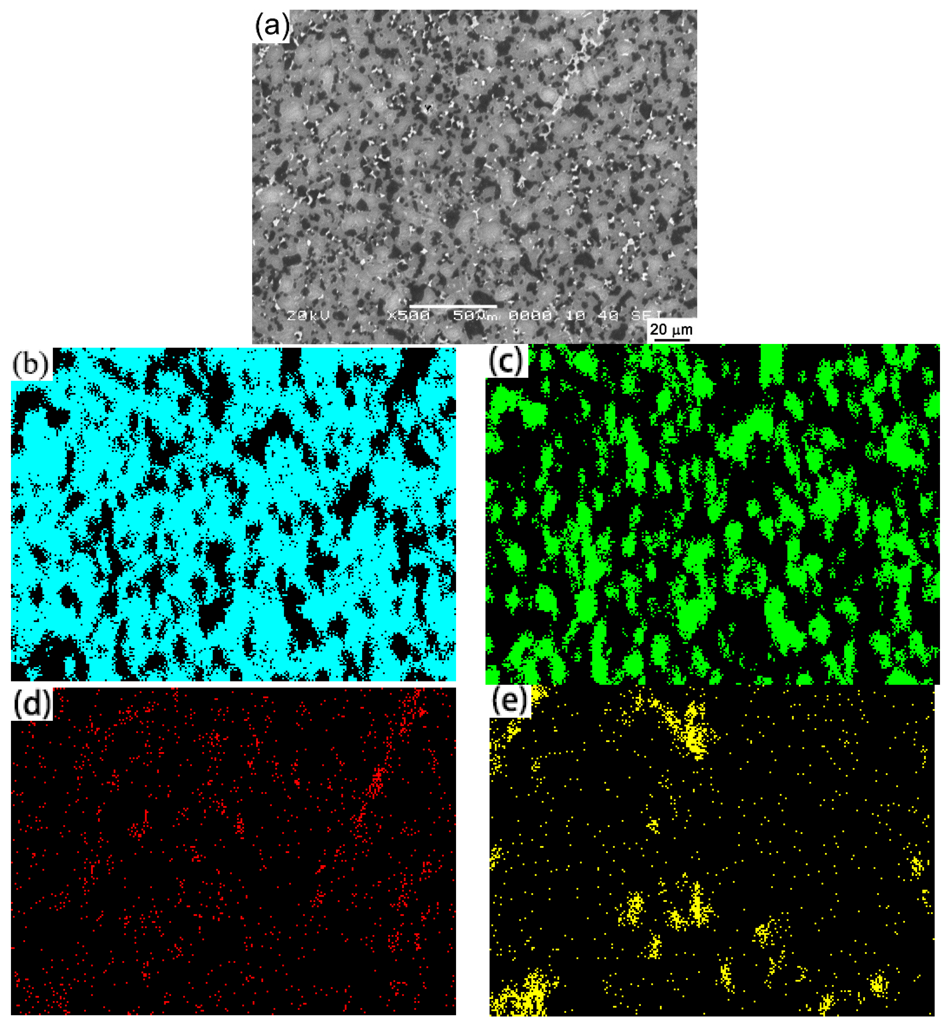
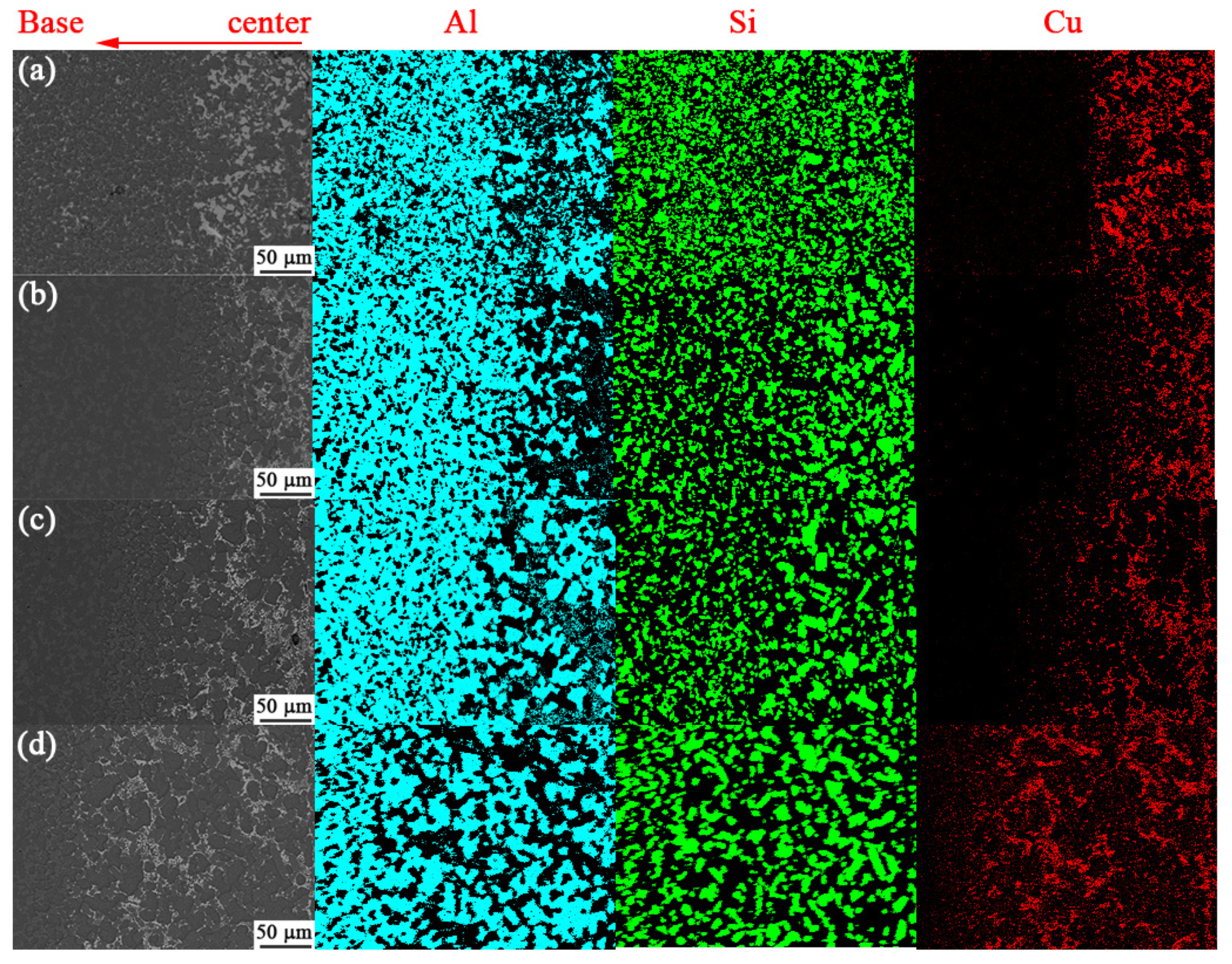
29]. In order to observe the diffusion of Cu atoms and distribution of Al-Cu compounds and Si particles, the region from the center of the brazing seam to the base material of the sample with holding a time of 7.5 to 15 min was subjected to elemental scanning using EDS to observe the diffusion of Cu element and the change of Si distribution. It can be clearly seen from the elemental distribution of Cu atoms in
Figure 6 that the distance of diffusion of Cu into the Al-Si base metal became longer with the holding time prolonging. Cu element in the brazing seam was mainly in the form of the Al-Cu eutectic compound, which is consistent with the phenomenon that the Al-Cu compound migrated into the base metal. Another phenomenon in
Figure 6 is the obvious change in Si phases. When the holding time was 7.5 min, the size of Si particles in the brazing seam was close to that in the base material. When the holding time was extended to 10 min, Si particles in the brazing seam began to be coarsened, but a certain amount of Si particles retained their fine distribution. With the holding time prolonged to 12.5 min or 15 min, large amounts of Si particles in the brazing seam were coarsened, and the size of Si particles in the base material was significantly finer than that in the brazing seam.
From the right column of
Figure 5, it can be found that a large amount of Si particles was aggregated at the interface between the base metal and the brazing seam. This phenomenon was verified in the mapping scan of
Figure 6. When the temperature reached the Al-Si-Cu ternary eutectic temperature, a liquid phase appeared in the brazing seam. But at this time, there were still many Si particles in the solid state. Some of these Si particles existed in the liquid phase, but more Si particles entered on the surface of the liquid phase, that is, at the junction between the base metal and the brazing seam. With the end of the heating and holding process, the liquid phase solidified, with these Si particles staying at the junction. In fact, similar grain growth near the brazing seam was also observed in [
30]. The distribution of Si particles in
Figure 5a and
Figure 6a show that when the holding time was 7.5 min, Si particles at the junction were still very small, and the dense Si particles were distributed at the junction of the base metal and the brazing seam. From the distribution of Si particles in
Figure 5b and
Figure 6b, it can be seen that when the holding time was extended to 10 min, the number of Si particles at the junction was much less but the size of Si particles was bigger than that at 7.5 min. At this time, a small amount of fine Si particles still existed at the junction. When the holding time was extended to 12.5 min, it can be seen from the Si distribution in
Figure 6c that the fine Si particles almost disappeared at the junction. Compared with the dense particles in the interface at 7.5 min and 10 min, the interface at 12.5 min was much “cleaner”, and the remained small particles were distributed at the junction. When the holding time was extended to 15 min, as shown in
Figure 6d, the interface is much “cleaner” than before, and Si particles at the interface between the base metal and the brazing seam were grown, and the size was slightly smaller than the size of the Si particles in the brazing seam.
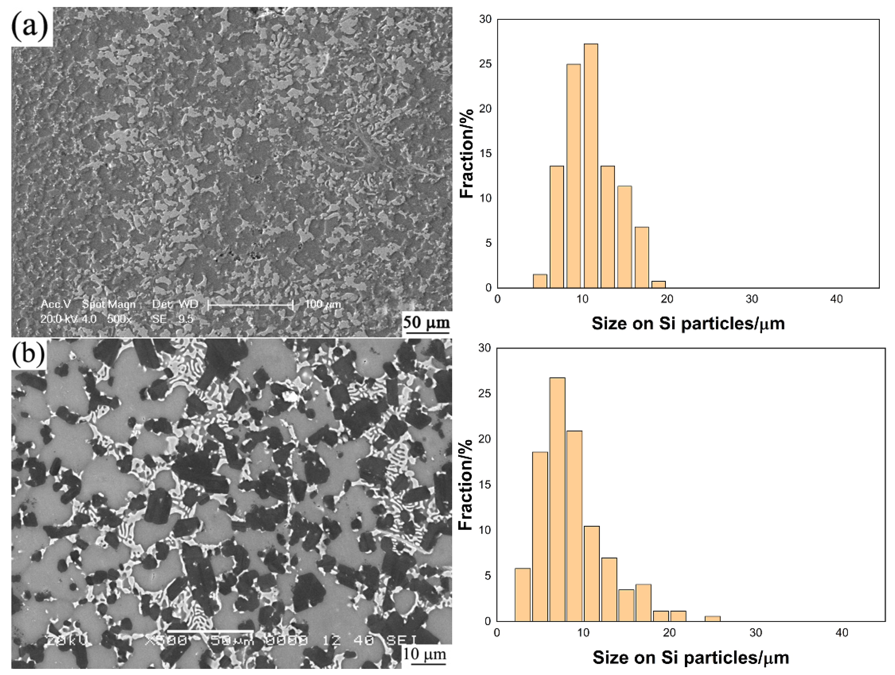
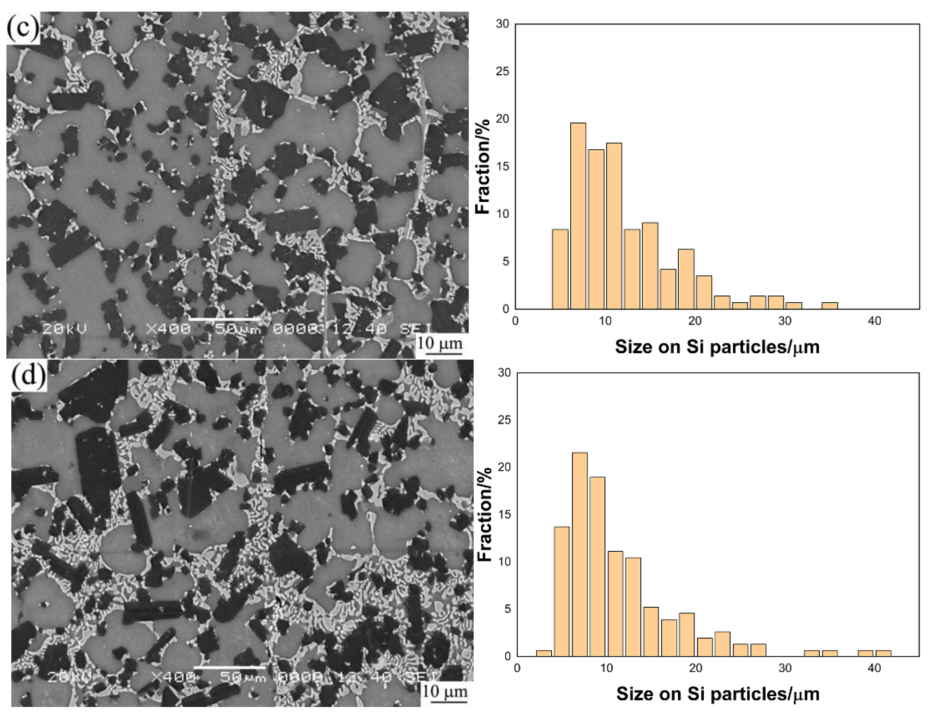
In summary, the holding time needs to be strictly controlled during TLP bonding of Al-Si alloy. A shorter holding time will cause joint defects, while an excessive holding time will change the distribution of elements in the brazing seam and have a deteriorated influence on the performance of joints. Therefore, the microstructure of the brazing seam was observed at higher magnification with the results shown in
Figure 7. The size of Si particles at different holding times was measured and investigated in detail. In the case of the distribution of Al
2Cu IMCs, they were mainly distributed around Si particles with a network structure. In the case of the size of Si particles in the brazing seam, since our alloy was made by the spray-forming method, Si was uniformly distributed in the metal matrix, and the particle size of Si particles in the Al-25Si-4Cu-1Mg alloy was about 10–15 μm. The size of Si particles in the brazing seam at different holding times was compared. It is found that when the holding time was 7.5 min, the size of Si particles was close to that of the base material, and above 90% of Si particles was below 15 μm. With the holding time increasing, the size of Si particles in the brazing seam gradually increased. When the holding time was 10 min and 12.5 min, Si particles reached 25 μm and 35 μm, respectively. When the holding time reached 15 min, Si particles with a size of 45 μm were produced. As the time increased, the coarsened Si not only increased in number but also increased in size, which would deteriorate the mechanical properties of the joint. The shear properties of the joint are also confirmed in a later section.
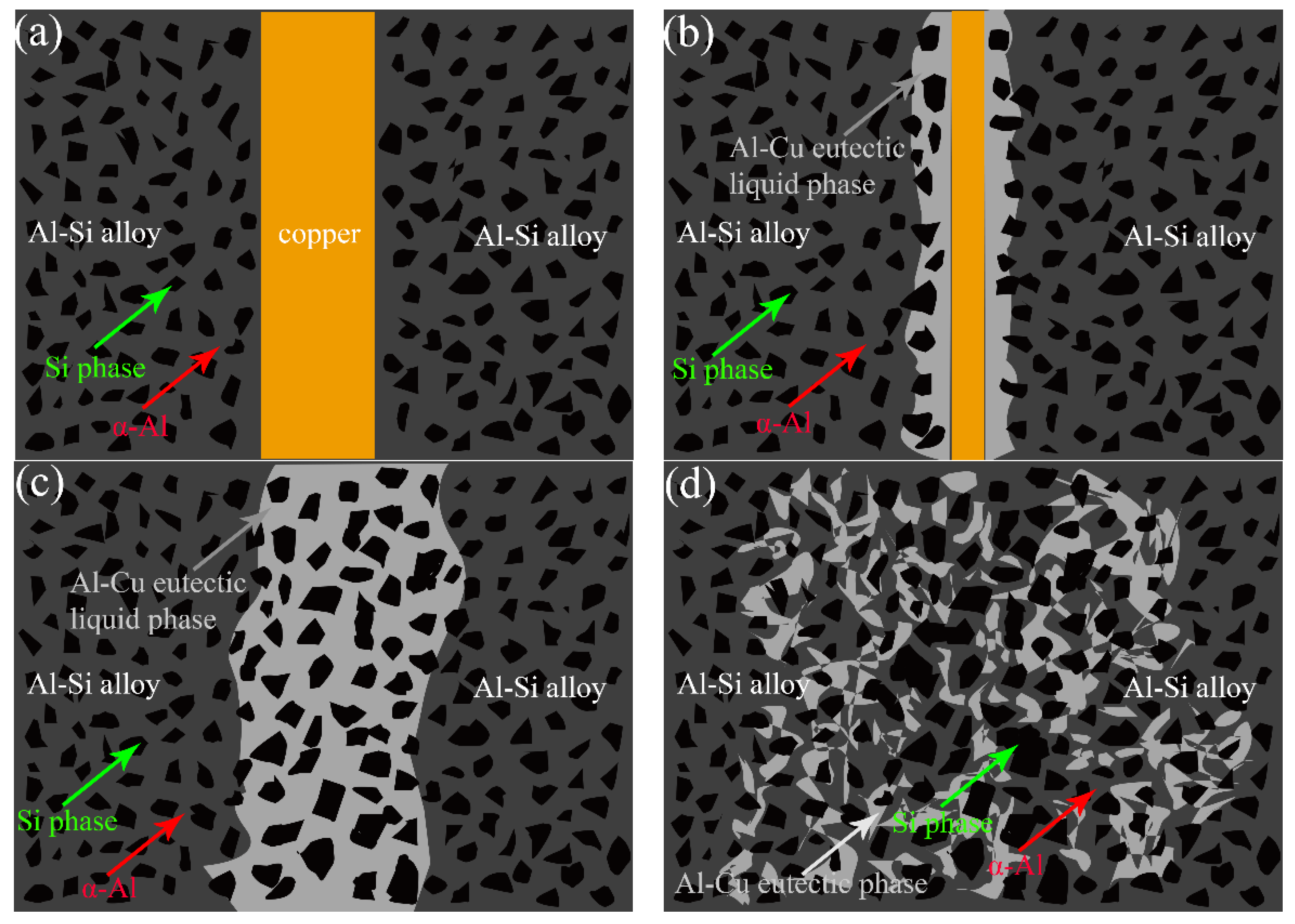
Figure 8 shows the model on the formation of the micro-morphology in the joint.
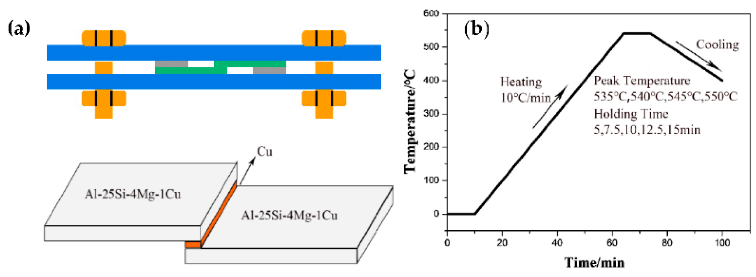
Figure 8a shows the initial state before bonding. The formation of the joint is achieved by element diffusion. Al in the base metal has strong miscibility with Cu and will inter diffuse with Cu in the presence of a concentration gradient. At high temperature, the majority of Si remains in the solid state. The formation of a joint is divided into two parts: the mutual diffusion between Al and Cu and the migration of Si atoms into the brazing seam. In the mutual diffusion between Al and Cu, Cu diffuses into the base material. Since the grain size of Al atoms is larger than that of Cu atoms, it is easier for Cu atoms to enter the grain lattice of Al during the diffusion process [
31]. With the temperature increasing, under the influence of pressure on the sample, the oxide film on the surface of the Al substrate will have gaps, which are mainly generated at the edge of solid Si particles. When the gap becomes larger, the Al element in the base metal comes into contact with Cu. Because there is only 4% Cu in the base material, the concentration difference between the brazing seam and the base material will be produced at this time, and accordingly, Cu begins to diffuse into the base material. When the temperature reaches the eutectic temperature of Al-Si-Cu, a small amount of liquid phase begins to form at the joint, as shown in
Figure 8b; the initially generated liquid phase will also affect the oxide film. With the temperature increasing, more liquid phases are generated, the oxide film becomes smaller and the contact area between the base material and the intermediate layer Cu becomes larger, Finally, all Cu reacts with Al near the brazing seam to produce a eutectic solution, as shown in
Figure 8c. With the diffusion continuing, Cu atoms enter into the base material in the form of Al-Cu intermetallic compounds. These eutectic fluids flow along the grain boundaries of α-Al and Si phases, while Cu in the Al-Cu compound will continue to enter α-Al, resulting in the decrease in Cu element concentration. Accordingly, Cu element concentration is equivalent to the base material, and the diffusion tends to stop. At this time, most Si still exists in a solid form. These Si elements will not flow to the base material with the eutectic solution, and the smaller Si particles will gradually evolve into larger Si particles. After the heating and holding process is complete, the eutectic liquid phase into the base metal will begin to solidify, and the dendritic Al-Cu eutectic phase is gradually formed. The original small Si particles in the base metal also become to be coarsened, as shown in
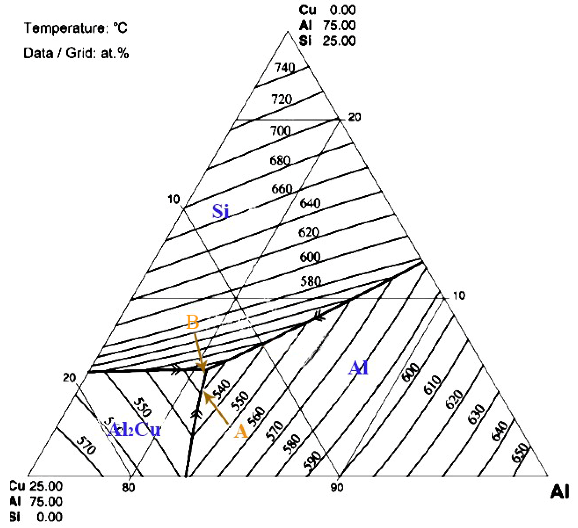
Figure 8d. It is possibly induced by the ternary eutectic reaction of Al, Si, and Cu after the temperature reaching the eutectic temperature. However, when the temperature sets at 540 °C, the actual composition of the resulting liquid phase will deviate from the ternary eutectic composition, where the content of Si will be less than the ternary eutectic composition. At this time, most Si will not be dissolved. As can be seen from point A in the ternary phase diagram shown in
Figure 9, the solidified phase at this time is an Al-Cu binary eutectic phase (θ-Al
2Cu + Al). The actual composition of the residual liquid phase will reach the ternary eutectic composition, as shown at point B in
Figure 9. Therefore, the solidification path is probably with the following sequence:
among which the main eutectic should be Al-Cu eutectic phase. With the increase in holding time, the fine Si particles will be aggregated and coarsened under the flow of the eutectic liquid phase. This produces great advantages compared to the traditional solidification process after the fusion welding of high eutectic Al-Si and the process of casting high eutectic Al-Si alloy. Due to the high temperature of fusion welding and casting, Si content in the liquid phase will exceed the ternary eutectic composition, and the Si phase will be first precipitated during solidification, which will greatly deteriorate the mechanical properties of the joint.
3.4. Mechanical Properties of TLP Joints
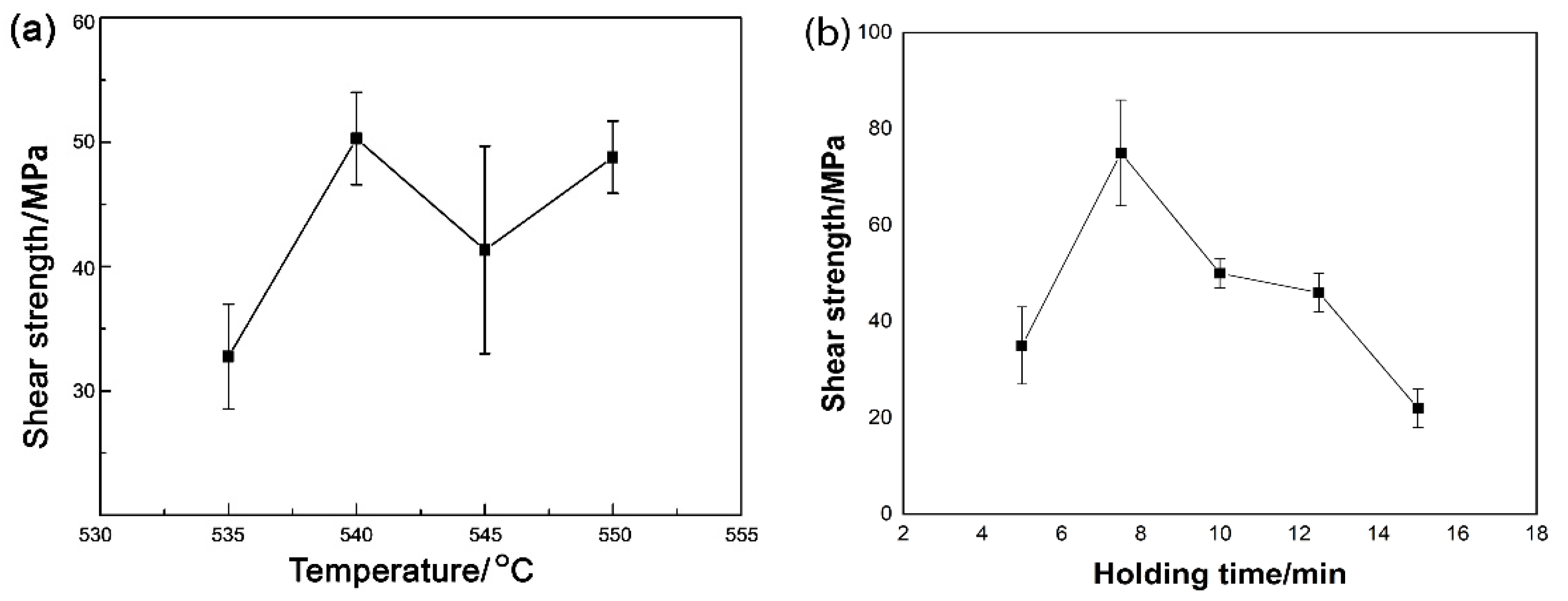
The shear properties of brazing joints were tested, and the shear strength of joints was calculated according to the maximum load. The results at different brazing temperatures and holding times are plotted in
Figure 10. During the effect of brazing temperature, as can be seen from
Figure 10a, the shear strength of the joint reached the maximum at 540 °C. At 535 °C and a retention time of 10 min, the shear strength was approximately 30 MPa. As the temperature increased to 540 °C, the shear performance reached a maximum value of about 50 MPa. With the temperature continuously increasing, the shear strength of the joint decreased slightly. The reason may be attributed to the formation of more Al
2Cu IMCs in the joint. Voids also began to appear in the joint. Excessive IMCs and voids will reduce the mechanical properties of the joint. During the effect of holding time, as can be seen from
Figure 10b, when the holding time was 5 min, a large number of voids were produced in the joint, which induced poor mechanical properties. With the holding time reaching 7.5 min, the shear strength of joints reached the maximum, about 75 MPa. With the holding time furtherly increasing, the shear property of the joint gradually decreased. With 15 min holding time, the shear strength of the joint was only 22 MPa, which was even lower than that of joints with a holding time of 5 min. From
Figure 10b, it can be seen that the joint with longer holding times but without defects would be even weaker than that with defects produced at a shorter holding time. When the holding time was 7.5 min, the brazing seam was mainly composed of distributed Al-Cu IMCs, α-Al phase, and finer Si particles with sizes within 20 μm. They had pinning effects on the microstructure, and furthermore, Si particles in the brazing seam were tightly combined with the adjacent aluminum-based solid solution, which provided the expansion resistance for cracks generated by the external force and then enhanced the mechanical properties of joints. With a prolonged holding time, Al-Cu intermetallic compounds gradually changed from a sheet-like uniform distribution to a dendritic aggregation distribution, and Si phases were obviously coarsened in the brazing seam. Moreover, large amounts of Si particles were segregated at the interface between the brazing seam and base metal and would seriously deteriorate the mechanical properties of joints, which was confirmed by observation on the later fracture analysis.
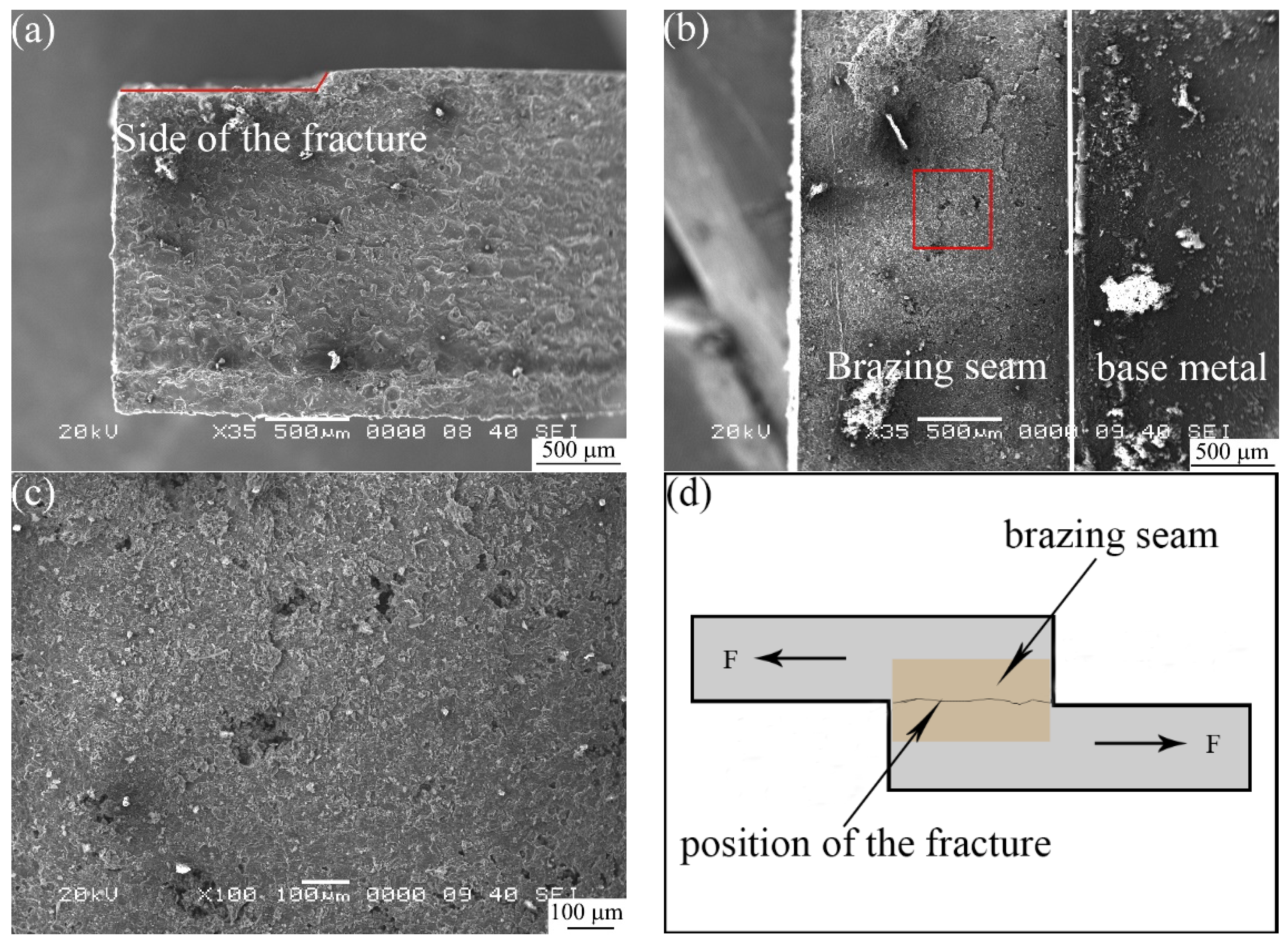
Figure 11 shows the typical fracture morphologies of joints finished at the brazing temperature of 540 °C.
Figure 11a is the side profile of the fracture, and the fracture occurred within the base metal.
Figure 11b is the observation of the fracture from the top view. The left part is the brazing seam and the right part is the base metal. Combined with
Figure 11a, the fracture position should occur along the interface between two pieces of base metals.
Figure 11c shows the magnified observation of the red area in
Figure 11b, it can be seen that the fracture surface is smooth without the appearance of dimples, which belongs to a typical brittle fracture. There are some small white spots in the fracture, which are the primary Si. From the observation of the interfacial structure shown in
Figure 3 and
Figure 4, the continuous reticulate Al
2Cu IMCs and coarsened Si particles at the interface of brazing joints had a deteriorating effect on the shear properties of the joints, which induced the fracture propagating along the center within the brazing seam, as shown in
Figure 11d.
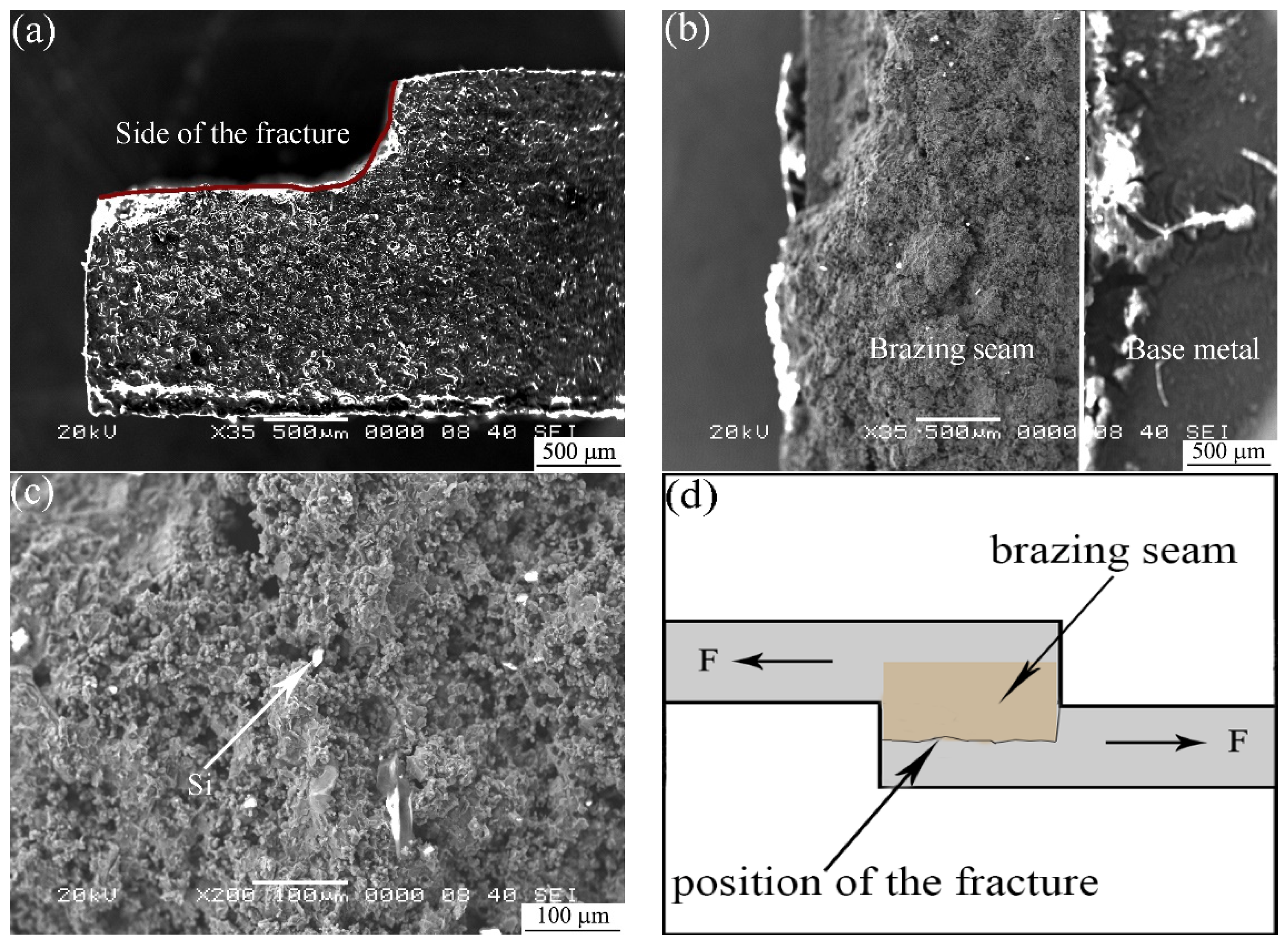
Figure 12 shows SEM images on the fracture morphology and the fracture propagation that occurred in the joint bonded at 540 °C for 7.5 min. From the side and top observations, as shown in
Figure 12a,b, the fracture mainly occurred at the interface between the brazing seam and base metal, as shown in
Figure 12d, which was different from the joint with a longer holding time in
Figure 11d. It can also be seen that the fracture mode is a quasi-plastic fracture with observable Si particles. The fracture mainly occurred in the base metal, while a longer holding time would cause the fracture to occur at the interface in the brazing seam.
The mechanical properties with a holding time of 7.5 min are better than the mechanical properties with a holding time of 10 min. The reason is related to the fracture position of the joint. When the holding time was 7.5 min, the joint fractured at the junction of the brazing seam and the base metal. According to the element distribution in
Figure 6a, the fracture location was at the Si particle aggregation area between the base material and the brazing seam. From
Figure 7a, the size of Si particles was smaller and the IMC distribution was uniform at the brazing seam with a holding time of 7.5 min. In combination with the fracture side view of
Figure 11a, the weakness of the joints was located in the area between the brazing seam and the base metal with Si particle aggregation. A large amount of Si particles aggregate was detrimental to the strength of the joint because they were easily cracked under lower stress. However, when the holding time was extended to 10 min, the joint was broken at the center of the brazing seam. In view of
Figure 6b, a large number of coarse Si particles can be seen at the brazing seam. This coarse primary crystal phase will deteriorate the strength of the joint. With the extension of the holding time, the shear strength of the joint will gradually decrease, which was consistent with the result of
Figure 10b. It can be seen from
Figure 6 and
Figure 7 that when the holding time reached 12.5 min and 15 min, long Si particles appeared in the brazing seam. The mechanical properties of this Si were more unfavorable for the joints [
20].


