Article

Effect of Bimodal Grain Structure on the Microstructural and Mechanical Evolution of Al-Mg/CNTs Composite

by
Behzad Sadeghi
1 and
Pasquale Cavaliere
2,*
1
Centre of Excellence for Advanced Materials Application, Slovak Academy of Sciences, Dubravska Cesta 9, 84511 Bratislava, Slovakia
2
Department of Innovation Engineering, University of Salento, Via per Arnesano, 73100 Lecce, Italy
*
Author to whom correspondence should be addressed.
Metals 2021, 11(10), 1524; https://doi.org/10.3390/met11101524
Submission received: 20 July 2021 / Revised: 16 September 2021 / Accepted: 23 September 2021 / Published: 26 September 2021
(This article belongs to the Special Issue Advances in Powder Metallurgy)

Abstract

:
The Al-Mg alloy structure reinforced with carbon nanotubes was evaluated after the composites production through a modified flake metallurgy technique followed by hot extrusion. The obtained bimodal microstructure of the matrix allowed to identify the microstructural mechanisms leading to high strength; uniform elongation and strain hardening ability of the produced composites. The presence of Mg transformed the native Al2O3 layer into spinel MgAl2O4 nano-phases dispersed both inside CG and UFGs and on the interfaces, improving the interfacial bonding of Al-Al as well as Al-CNT. The effect of the reinforcing phases percentages on the dislocations mechanisms evolution was evaluated through stress relaxation tests leading to the underlying of the effect of reinforcing phases on the modification of the interphase influence zone

1. Introduction

Metal matrix composites (MMCs) production and application have been limited by the well-known phenomenon of “strength–ductility” trade-off [1]. In traditional composites reinforced with micrometer ceramic phases, the strengthening is due to the stop or the deflection of propagating cracks active as the matrix is weakened [2]. Many defects at the matrix-reinforcement interphases and reinforcing phases structure are revealed during loading [3]. The design trend in the recent past has been characterized by the employment of nanometric reinforcements acting through completely different mechanisms [4]. The use of carbon-based nanometric reinforcements such as carbon nanotubes (CNTs) or graphene led to the improvement of both strength and toughness by avoiding any fracture in the reinforcing phase [5]. In addition, in these composites, the matrix grain size refinement provides increased grain boundary strengthening in comparison with traditional MMCs [6]. As the result, the MMC’s strain hardening ability was much weakened due to evident dynamic recovery of nano or ultrafine grains (NG/UFG), and easy strain localization in the nano-structured matrix has emerged as a new problem for improving nanocomposite’s strength while maintaining its ductility [7].
Many different microstructures with various reinforcement type, such as bimodal, gradient, harmonic, and nano-laminated, result in the effective restoration of strain hardening ability and improved ductility of NG and UFG metals [8]. The main recognized mechanism for the effective at increase of the ductility/strain hardening ratio is dislocation annihilation hindering at the grain boundary, which is capable of promoting intergranular dislocation interaction leading to a high long-range internal stress or back stress [9]. The increased back stress depends on the deformation mode among heterogeneous phases with consequent accumulation of geometrical necessary dislocations (GNDs) [10]. Given much research evidence regarding bimodal structures, Lavernia and co-workers proposed the idea of “trimodal structure” to solve the problem of high strength but low ductility in metal matrix nanocomposites (MMNCs) [11]. These trimodal structures consist of nanostructured reinforcing phases embedded in a bimodal UFGs or NGs and coarse grains (CGs). In these cases, the blunting effects of reinforcements at the UFGs-NGs/CGs interfaces produces an increment of ductility and toughness [12]. This general behavior has been also observed in CNTs reinforcing Al alloys [9]. Here, the bimodal microstructure of the matrix allows for the pronounced improvement of mechanical properties. The main objective of the current paper is to focus on the effect of bimodal structure design on dislocation motion and plastic deformation behavior. In the present study, the stress relaxation compression test was applied to reveal the evolution of back/effective stress and apparent activation volume during the plastic deformation of uniform and bimodal aluminum matrix composite reinforced with CNTs. Even if the research in the field is very broad, many clarifications are needed about the competing mechanisms acting during the materials’ deformation. Much evidence is derived from the effect of soft phases on the crack propagation behavior [13]. These results are very pronounced in graded or multi-layer composites capable of improving insufficient strain hardening ability of the NG/UFG metal matrix [14]. In the present study, all these mechanisms were evaluated in the case of plastic deformation of uniform and bimodal MMNCs. The CNT reinforced Al-Mg (CNT/Al-Mg) nanocomposites were produced through a modified flake powder metallurgy technique. The strengthening effect of CNT on mechanical properties and dislocation behavior was discussed. Electron back scattering diffraction and TEM characterization were conducted to reveal the grain structure and dislocation motion before and after mechanical testing. The effect of heterogeneous interfaces on plastic deformation in the different bimodal structures was discussed, providing insights for the bimodal structure design in high-performance MMNCs.

2. Experimental Procedure

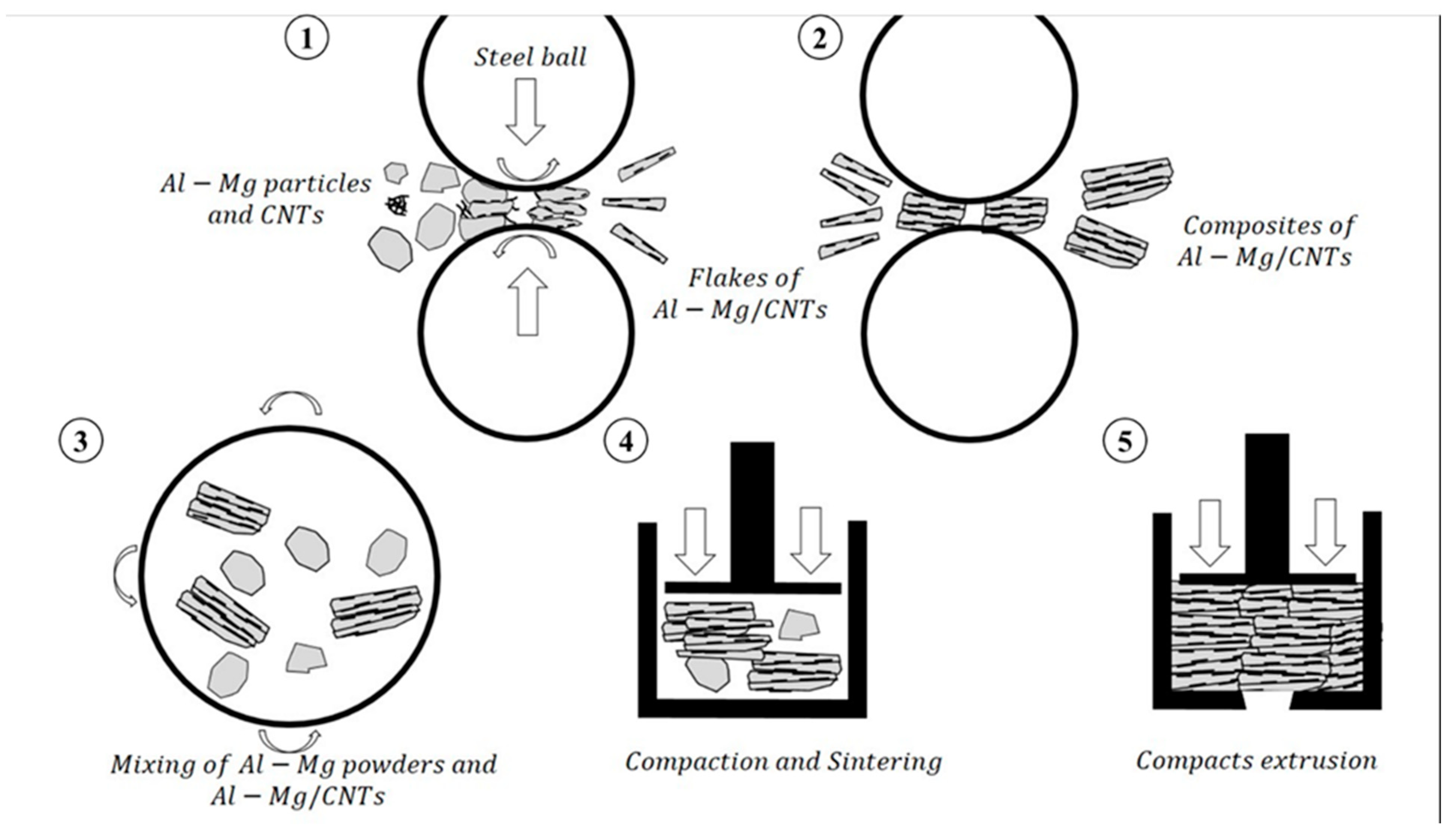
2.1. Raw Material and Composite Fabrication

Al-Mg powders (5083Al, 4 wt.% Mg, 0.5 wt.% Mn and 0.1 wt.% Cr) with average particle size of 20 μm were used as the matrix material. Multi-walled CNT (99.9% in purity fabricated via catalytic vapor deposition) of ~10 nm in diameter and 10 μm in length were used as the reinforcement. For both the uniform and bimodal CNT/Al-Mg nanocomposites, the CNT content was set at 1 and 1.5 wt%. The schematic of the employed process is shown in Figure 1. The CNT/Al-Mg composite powders (with CNT content of 1 wt.%, 1.5 wt.%) were prepared following this procedure: (1) to ensure the breaking of CNT clusters, they were dispersed in ethanol, assisted by an ultrasonic shaker (house made) for 1 h to obtain a gel-like dispersion. After that, the Al-Mg powders were added in the gel-like CNTs–ethanol solution, stirred and then dried in vacuum at 70 °C for 2 h to obtain CNTs/Al spherical powders. To make the composite, flake powder metallurgy (PM) was prepared via a dual-speed ball milling (BM) route conducted using a planetary ball mill (house made) at low-speed BM (LSBM) at 160rpm for 8h, hereafter denoted as 160/8, followed by high-speed BM (HSBM) at 270rpm for 1h, hereafter denoted as 270/1, using a stainless-steel jar and balls with a ball-to-powder weight ratio of 20:1 in an argon atmosphere at 1 atm. In our preliminary experiments, with such a combined solution approach, LSBM and HSBM provided prerequisites needed for our study, namely achieving uniform CNT dispersion in Al flakes by LSBM, and good bonding of CNT/Al flakes through HSBM. To prepare the bimodal CNT/Al-Mg nanocomposite the 1.5 wt.% composite powders were separately blended with raw Al-Mg powders using weight ratios of 3:1 before compaction. To consolidate the CNTs/Al composite powders, vacuum hot pressing (VHP) (house made) was used. The powder mixtures were first cold pressed into powder compacts, and then sintered at 550 °C for 2 h by VHP in a graphite mold. The sintered materials were finally extruded at 450 °C and annealed at 500 °C for 1h. For comparative results, the Al–Mg alloy without CNTs was also prepared by the same process.

2.2. Material Characterization and Mechanical Tests

Raman spectrum (Senterra R200-L, Bruker, Karlsrue, Germany) was applied to identify the CNTs reservation after fabrication in the spectral range from 400 to 2000 cm−1. Careful X-ray diffraction scanning (XRD-6100, Shimadzu Co. Ltd., Kyoto, Japan) was performed to measure the dislocation density using the W-S method. Optical microscopy (OM, Zeiss Axiovert 200 MAT, Oberkochen, Germany), electron backscattered diffraction (EBSD, Tescan Mira3, Brno, Check Republic) analysis, high resolution TEM observation, were jointly applied to reveal the microstructure evolution of matrix grain and dislocation motion. To evaluate the material’s mechanical property, dog-bone shaped specimens were machined from extruded rods with gauge length of 20 mm and diameter of 4 mm for quasi-static tensile test at the strain rate of 5 × 10⁻⁴ s−1 using a universal testing machine (Zwick-100, Genova, Italy). Cylindrical pillars of 2 mm in diameter and 4 mm in height with the long axis parallel to extrusion direction were wire-cut from the extruded bar. Stress relaxation compression test was conducted on the as-prepared pillars using Instron 100 at the strain rate of 5 × 10⁻⁴ s−1.

3. Results and Discussion

Figure 2a,b shows the SEM images of as sintered Al-Mg alloy and Al-Mg/CNT composite. The microstructure manily consists of coarse grains in the micrometer range that were embeded in the UFGed matrix. Some grains became darker due to their faster etching rate as well as the lower magnification used. In addition, CNTs’ hardening increases due to phase work, leading to significant grain refinement to form fine grains. The presence of CNTs in the Al-Mg/CNT composite cause preservation of the UFG regions during the sintering process, and hinder grain growth of the CG regions. In addition, in such a bimodal microstructure, it is expected that the differences in the homogeneity of plastic deformation should be accounted for. Thus, bimodal grain structure with uniformly distributed fine and CG regions were successfully fabricated through the addition of raw Al–Mg alloy powders during the powder sintering process.
Figure 3a–c depicts the OM images of the Al-Mg, Al-Mg/1.5 wt.% CNTs after extrusion and annealing. No porosity was detected during the OM examinations. The CG (white area) with grain sizes of the order of several micrometers were nicely distributed in the UFG matrix (gray area). The grains in both the CG and UFG sizes elongated along the extrusion direction. Comparing the unreinforced Al-Mg (Figure 3a) with other OM images in Figure 3b,c, the CNT strengthening contribution due to grain refinement in the Al-Mg composite containing CNTs is obvious. From the OM images, it can also be found that some CGs are elongated both in the Al-Mg alloy and the Al-Mg/CNT composite. However, the fraction of the elongated grain after annealing decreases and random distribution of CG increases with Image-Pro Plus 6.0 (IPP 6.0) software (Media Cybernetics, Rockville, MD, USA) area fraction of the CG zones in after extrusion and after annealing were determined to be ~33% and ~9%, respectively. This could be due to dynamic recovery and recrystallization occurring in CGs, and consequently significant grain growth of CGs. It should be noted that UFG undergoes no grain growth thanks to the strong inhibiting effect of CNTs on grain boundaries. Figure 3d shows the TEM microstructure of the compacts containing 1 wt.% of CNTs in an extruded condition, then Figure 3e,f show the materials containing 1.5 wt.% and 1.5 wt.% of CNTs after extrusion and annealing. Obviously a bimodal garin size distribution exists in all the samples both before and after the annealing treatmeant. In fact, it can be interpreted that CG are embedded into a UFG matrix. All the composites depict an analogus selected area electron diffraction (SAED) pattern from the UFG zone confirmed by the UFG structure.
Comparison of the OM and TEM images shows that most grains in as-extruded Al-Mg/1.0 wt.% CNTs, as-extruded Al-Mg/1.5 wt.% CNTs, and as-annealed Al-Mg/1.5 wt.% CNTs are UFGs and the average grain sizes are about 900, 650, and 500 nm, respectively.
Raman spectrums in Figure 4a showed the structure integrity of CNTs statistically. Two main peaks in the Raman spectrums, D-(1350 cm−1) and G-(1580 cm−1) bands, are often used to characterize the structure of CNTs. Generally, the G-band reveals highly crystalline graphite layers, and the D-band reveals the presence of defects in the graphite layer. Therefore, the analogous intensity ratio of D- and G-bands (ID/IG) of the CNTs which were 0.97, 0.98; slightly higher than the value of raw CNTs (0.94), indicates similar degree of graphitization and damage. This slight increase in the ratio of ID/IG corresponds to slight damage of the CNT structure that causes the formation of nano rods of Al4C3 in the aluminum matrix.
Figure 4b,c shows XRD patterns of the materials in as-extruded and as-annealing conditions, respectively. Obviously, diffraction peaks of Al4C3 were found in both composites containing 1 and 1.5 wt.% of CNTs for as-extruded and as-annealed conditions. XRD results show unreinforced Al-Mg (Al-Mg alloy) in as-extruded and as-annealed showed a typical diffraction peak of Al.
From at the XRD patterns as-annealing it can be confirmed that the formation of spinel phases of MgAl2O4 precipitation in the composites containing 1.0 and 1.5 wt.% of CNTs, due to oxidation of Mg [15,16]. In fact, the presence of such a phase was in consistent with the findings of Ref. [17]. Due to both the small amount of elements and the low accuracy of the XRD facilities, other compounds such as γ -Al2O3 [18] should not be identified even if they exist.
Figure 5 underlines the presence of carbon nanotubes in the studied materials. The CNTs are uniformly dispersed in the UFG zones, and no CNTs are observed in the CG regions.
The CNTs are mainly distributed at the grain boundaries in UFG regions (yellow arrows), which can effectively hider grain growth due to the Zener pinning effect. In addition, a few numbers of a polyhedral spinel MgAl2O4 (marked by blue arrows) were detected in TEM images which were previously confirmed by XRD results. To identify its structure, fast Fourier transform (FFT) is given in the insert Figure 5c. The presence of such a phase improves the direct CNT-Al interfacial bounding in the interfaces, specifically UFG/CG interfaces. This is consistent with the finding of Ref. [17].
So, it can be interpreted that the UFG zones can be preserved during consolidation, while the CGs without CNTs grow significantly. In addition, the CNTs are uniformly dispersed in the UFG zones, and no CNTs are observed in the CG zones. From our previous papers [9,19], the accumulation of geometrically necessary dislocations (GNDs) accompanied with blocked mobile dislocations at grain boundaries of CG/UFG and CNT/Al interfaces forms a grain boundary affected zone (GBAZ) with a thickness of several nanometers (33–36 nm [19]).
Figure 6a shows the EBSD microstructure of the compacts containing 1 wt.% of CNTs in as-extruded condition, then Figure 5b,c show the materials containing 1.5 wt.% and 1.5 wt.% of CNTs after extrusion and annealing. The majority of grains in all the samples are observed to be elongated grains with relatively fibrous texture along the extrusion direction. As given in inserts Figure 6a–c, the average grain sizes (equivalent circle diameters) of the as-extruded Al-Mg/1.0 wt.% CNTs, as-extruded Al-Mg/1.5 wt.% CNTs, and as-annealed Al-Mg/1.5 wt.% CNTs are ~850 nm, 600 nm, and 500 nm, respectively, which is consistent with the ones obtained from TEM images. The bimodal microstructure becomes more pronounced as the carbon nanotubes percentage increases. The matrix microstructure is UFG/CG with the reinforcements mainly distributed inside the UFGs. In addition, the local CNT content in the UFG regions of Al-Mg/1.5 wt.% CNTs composite is higher than that of Al-Mg/1.0 wt.% CNTs, which lead to the significant inhibition of grain growth in the UFG zone and an increased fraction of UFG.
The tentative conclusion can be drawn that the dislocated pile-up at the GBAZ zone significantly develops forest dislocations and back stress in the UFG zones and produces long-range stress fields onto mobile dislocations moving toward grain boundaries, subsequently enhancing back stress hardening. On the other hand, the same interfaces formed between CG/UFG could act as dislocation sources and sinks to facilitate plastic deformation in CG zones.
Quasi-static tensile test and stress relaxation test results of CNT/Al-Mg composites are shown in Figure 7. A composite containing 1.5 wt.% of CNTs exhibited a yield strength (YS) of 430 MPa, ultimated tensile strength (UTS) of 476 MPa, and elongaltion of 5%. Compared to the Al-Mg alloy, introducing 1.5 wt.% and 1 wt.% of CNTs resulted in 95% and 60% increase in YS, 52% and 37% increase in UTS, and 55% and 45% decrease in elongation, respectively. It is worth mentioning that the composite containing 1.5 wt.% of CNTs showed more strain hardening capability compared to other materials. The Al-Mg/CNTs showed moderately enhanced Young’s modulus (E) and significantly improved YS and UTS, indicating good stiffening–strengthening effect of CNTs considering that CNTs and Al formed a strong bonding in the interfaces. In addition, individually dispersed spinel MgAl2O4 with smaller nano-size inside grains could also relieve stress concentration, and eliminate the early crack sources under tensile conditions, which was beneficial for ductility [17]. It is also obvious that tailoring bimodal structure generally leads to a noticeable increase of YS/UTS, but a decrease of elongation. Strain hardening rate is an index to determine the resistance of a material to necking, defined as Considere’s criterion [20]. Figure 7b shows that the composites containing 1.5 wt.% and 1 wt.% of CNTs maintained a relatively higher strain hardening rate compared to Al-Mg alloy (unreinforced material). As a general behavior, strain hardening ability increases as the carbon nanotubes content increases. The higher strain hardening rate corresponding to Al-Mg/CNTs can be attributed to the effect of bimodal grain structure. In fact, the softer CG zones deformed more than the UFG zones, therefore more dislocation was generated within the CG zones and they glided easily through the CG to reach the CG/UFG interface, to be consequently eliminated. The mobility of dislocations is limited within UFG zones because of the smaller grains. Since the total strain must be equal in both UFG and CG zones, any strain differences between UFG and CG zones in internal strain must be accommodated ultimately. Hence, different deformation mechanisms should be active near UGF/CG interfaces to accommodate the equal strain. From a fractography point of view, fast propagation of cracks through UFG regions can be delayed by plastic deformation and crack blunting in CG regions as previously reported by [21].
The flow stress required for dislocation movement has two components: athermal (back) stress and thermal (effective) stress. The former corresponds to the long-range interaction of dislocation with large obstacles while latter is related to short interaction dislocation with localized obstacles such as dislocation tangles [22]. During relaxation, both back and effective stresses as the rate dependent component are believed to be relaxed during the stress relaxation test. More specifically, the work hardening rates of the Al-Mg/CNT composites and the Cu matrix after yielding were shown to be different, suggesting that the grain boundary-controlled dislocation density strengthening mechanism is likely to play a dominant role in the present study. Stress relaxation is defined by the decrease in stress during the holding period (constant total strain), at a constant temperature. Figure 8a shows the progressive stress relaxation cycles of the unreinforced Al-Mg alloy and the Al-Mg/CNT composites. At stress levels below ~78 MPa, all the samples were still in the elastic regime and no detectable stress decay was observed. However, starting at the stress level of ~78 MPa, appreciable stress relaxation in both samples occurred, and the decay magnitude for each relaxation cycle increased with higher stress levels. Such a gradual stress drop is generally thought to be due to dislocations moving across localized barriers [23], such as dislocation forests and tangled- and solute atoms, when the total strain of the sample is constant. This finding is consistent with the results reported by Fu et al. [24]. The stress decay is less pronounced as the carbon nanotubes content increases. Back stress, effective stress, and apparent activation volume were calculated for all the materials through the compression behavior based on the equation Refs. [23,24].
Figure 8b,c represent the back and effective stress for the materials, where the back stress for the composite containing 1.5 wt.% of CNTs is about 354 MPa, giving rise to its corresponding higher YS. In addition, it should be stated that the differences in the stress decay magnitude, back-, and effective stress in the materials become more significant when the relaxation experiments were conducted at a higher stress level. Comparing Al-Mg alloy and Al-Mg/1.5 wt.% CNT, show that the addition of 1.5 wt.% of CNTs results in a remarkable improvement of back stress from 300 MPa to 350 MPa at the strain of 5%, thanks to accumulating GNDs at CG/UGF interfaces. In contrast, in the Al-Mg/1.5 wt.% CNT, back stress decreased to 275 MPa at the strain of 5%. This may be related to the fact that CNTs during the ball milling process underwent a loss of structure integrity. Such a phenomenon causes weakens the efficiency of CNT in acting as a stiff and strong obstacle. The carbon nanotubes addition leads to an increase in the back stress more pronounced as the CNTs percentage increases. Obviously, as the grain size is reduced, the effect of back stress increases. A strong effect is also attributed to the increased bimodal matrix microstructure. In fact, the higher internal stress means a higher dislocation density, indicating the enhanced dislocation accumulation capacity in Al-Mg/1.5 wt.% CNT. This finding is in agreement with the results reported in [25].
Owing to the presence of CNTs and long-range effects of mobile dislocations moving toward the interfaces, and probably some Al4C3 (as a by-product of the reaction of broken CNTs with aluminum), MgAl2O3 particles and some γ -Al2O3 particles were broken, of which the latter mostly settled in the grain interiors, and the dislocation interaction degree increased, which in turn increases effective stress. The same phenomenon was found in graphene reinforced Al matrix composites [26]. In this way, the effective stress results were higher as the microstructure of the matrix moved away from a clear bimodal one. This behavior is attributed to the more promoted intragranular dislocation entanglement.
In a thermally activated process, a single relaxation event is thermally activated and can also be expressed by logarithmic variation of stress (Δσ) as a function of relaxation time (Δt) [27]
Δ σ = ( 3   kt V * )   ln   ( 1 + Δ t C r )
where k is the Boltzmann constant and T is the absolute temperature, V * is the apparent activation volume of plastic deformation, and C r is the time constant. As shown in Figure 8d, V * of all the materials decrease with increasing applied strain. This can be related to the much more difficult sliding dislocation due to dislocation forests, and the increase in its density. However, it is supposed that the mobile density is unchanged at low strain [28,29,30]. At room temperature, V * showed an inverse correlation with increasing CNT content. Therefore, it can be concluded that there is a significant difference in distinct thermal activation behavior governed in Al-Mg/CNT composite and Al-Mg alloy.
The XRD allowed for the calculation of microstrain and dislocation density. The results for the Al-Mg alloy and for both the composites are summarized in Table 1.
It is clear how the apparent activation volume increases as the percentage of deformation increases. This behavior is attributed to the increased effect of the dislocations’ entanglement as the amount of deformation increases [31,32]. So, the interaction between the moving dislocations and the various interfaces is more and more pronounced. As shown in Figure 8c, the apparent activation volume increases as the carbon nanotubes are introduced in the composites structure. The main effect of carbon nanotubes is to shift the behavior from the inter-dislocations mechanism to the dislocation-interfaces one. By considering only the composites, it should be underlined that this effect is more pronounced in the first stages of deformation and its effect is gradually reduced as the deformation accumulates in the material.
The EBSD maps of the studied materials after tensile tests is shown in Figure 9.
As the deformation accumulates, the statistical interaction among the moving dislocations starts to appear again [33,34]. So, the activation volume is very large in the first few percentages of deformation and then it saturates as the deformation accumulates. This saturation is much more pronounced as the CNTs percentage increases and as the bimodal microstructure is more effective. As a general behavior, the change in the activation volume follows the same trend of the change in the effective stress. The effective stress rapidly increases with constant speed and then it leads to saturation.
Since the UFG regions effectively have more contribution in plastic deformation compared to the CG regions [35], it can be concluded that the composite containing 1.5 wt.% CNT shows the best mechanical properties compared to the sample reinforced with 1.0 wt.% CNT and unreinforced one (Al-Mg alloy). In this case it is clear how the effect of bimodal microstructure is very effective in the modification of the effective stress. So, there is a fundamental reason because of the effects of differences in the matrix grain sizes’ configuration. In general, the CGed structure is constrained by the more resistant CNTs/UFG structure. This promotes the accumulation and the entanglement of intragranular dislocations. As the bimodal microstructure is less pronounced (at lower CNTs percentages), the CGed structure is less constrained during the deformation. In addition, the interface affected zones fill smaller volumes leading to a lower efficiency from the configuration. In this case the soft matrix starts to surround the hard UFG/CNTs structure, but this produces a more pronounced strain hardening in the soft matrix volume. This is the main reason for the gradual increase in the effective stress. Therefore, the soft and the hard phases deform together in the initial stages of deformation. The soft phase hardens more quickly and this is the main reason for the effective rapid stress increase, but also of the quick saturation as the deformation proceeds.

4. Conclusions

The modified flake powder metallurgy technique followed by extrusion successfully allowed preparation of Al-Mg/CNTs composites with different reinforcing percentages uniformly distributed in the matrix.
The reinforcing phases and the manufacturing process allowed obtainment of a bimodal UFG/CG microstructure in the matrix. The bimodal microstructure results were more pronounced as the CNTs percentage increases.
The stress relaxation tests allowed the conclusion that the bimodal microstructure leads to a reduction of back stress in the material. This improves the composite resistance and the strain hardening properties. This behavior is attributed to the number of grain boundaries and to their intrinsic resistance.
As the bimodal microstructure is more evident, the deformation constraint between the matrix and the reinforcement is experienced in the soft phase in the form of interphase influence zone. The larger this zone is, the stronger the constraint effect results. This leads to higher strength and uniform elongation.
The uniform tensile properties of the Al-Mg/CNT composites compared to Al-Mg alloy (un-reinforced sample) were mostly due to the constrained deformation of the CG (CNT-free) regions by means of UFG Al-Mg (CNT-enrich) regions. It should be stated that the volume fraction of UFG regions as a hard phase effectively affect the deformation mechanisms governed in the composites. For a bimodal microstructure dislocation, annihilation is still favorable at grain boundaries, specifically interfaces of the UFG regions, but generation of dislocations is mainly concentrated in the CG regions.
The transformation of Al2O3 into MgAl2O4 would cause the direct CNT-Al interfacial bonding in Al-Mg/CNT composites; as a result, the interfacial bonding was improved, and the early crack nucleation and propagation were delayed.

Author Contributions

B.S. Investigation; P.C. conceptualization, writing. All authors have read and agreed to the published version of the manuscript.

Funding

This work was performed during the implementation of the project Building-up Centre for advanced materials application of the Slovak Academy of Sciences, ITMS project code 313021T081, supported by Research & Innovation Operational Programme funded by the ERDF.

Institutional Review Board Statement

Not applicable.

Informed Consent Statement

Not applicable.

Data Availability Statement

Data will be available on request.

Conflicts of Interest

The authors declare no conflict of interest.

References

  1. Yang, M.; Weng, L.; Zhu, H.; Fan, T.; Zhang, D. simultaneously enhancing the strength, ductility and conductivity of copper matrix composites with graphene nanoribbons. Carbon 2017, 118, 250–260. [Google Scholar] [CrossRef]
  2. Ramakrishnan, N. An analytical study on strengthening of particulate reinforced metal matrix composites. Acta Mater. 1996, 44, 69–77. [Google Scholar] [CrossRef]
  3. Shao, J.C.; Xiao, B.L.; Wang, Q.Z.; Ma, Z.Y.; Yang, K. An enhanced FEM model for particle size dependent flow strengthening and interface damage in particle reinforced metal matrix composites. Compos. Sci. Technol. 2011, 71, 39–45. [Google Scholar] [CrossRef]
  4. Bagherpour, E.; Reihanian, M.; Miyamoto, H. Tailoring particle distribution non-uniformity and grain refinement in nanostructured metal matrix composites fabricated by severe plastic deformation (SPD): A correlation with flow stress. J. Mater. Sci. 2017, 52, 3436–3446. [Google Scholar] [CrossRef]
  5. Cavaliere, P.; Sadeghi, B.; Shabani, A. Carbon nanotube reinforced aluminum matrix composites produced by spark plasma sintering. J. Mater. Sci. 2017, 52, 8618–8629. [Google Scholar] [CrossRef]
  6. Chen, B.; Shen, J.; Ye, X.; Jia, L.; Li, S.; Umeda, J.; Takahashi, M.; Kondoh, K. Length effect of carbon nanotubes on the strengthening mechanisms in metal matrix composites. Acta Mater. 2017, 140, 317–325. [Google Scholar] [CrossRef]
  7. Yoo, S.J.; Han, S.H.; Kim, W.J. Strength and strain hardening of aluminum matrix composites with randomly dispersed nanometer-length fragmented carbon nanotubes. Scripta Mater. 2013, 68, 711–714. [Google Scholar] [CrossRef]
  8. Wu, C.; Ma, W.X.; Chen, Y.P.; Li, Y.; Chen, Y.; Li, J. Progress of the Current Interface Research on Carbon Nanotubes Reinforced Aluminum-matrix Composites. Adv. Mater. Res. 2014, 842, 196–200. [Google Scholar]
  9. Sadeghi, B.; Qi, J.; Min, X.; Cavaliere, P. Modelling of strain rate dependent dislocation behavior of CNT/Al composites based on grain interior/grain boundary affected zone (GI/GBAZ). Mater. Sci. Eng. A 2021, 820, 141547. [Google Scholar] [CrossRef]
  10. Wu, X.; Zhu, Y. Heterogeneous materials: A new class of materials with unprecedented mechanical properties. Mater. Res. Lett. 2017, 5, 527–532. [Google Scholar] [CrossRef]
  11. Jiang, L.; Ma, K.; Yang, H.; Li, M.; Lavernia, E.J.; Shoenung, J.M. The Microstructural Design of Trimodal Aluminum Composites. JOM 2014, 66, 898–908. [Google Scholar] [CrossRef]
  12. Ye, J.; Han, B.Q.; Schoenung, J.M. Mechanical behaviour of an Al-matrix composite reinforced with nanocrystalline Al-coated B4C particulates. Phil. Mag. Lett. 2006, 86, 721–732. [Google Scholar] [CrossRef]
  13. Ye, C.; Shi, J.; Cheng, G.J. An eXtended Finite Element Method (XFEM) study on the effect of reinforcing particles on the crack propagation behavior in a metal–matrix composite. Int. J. Fatigue 2012, 44, 151–156. [Google Scholar] [CrossRef]
  14. Chen, L.; Hou, Z.; Liu, Y.; Luan, C.; Zhu, L.; Li, W. High strength and high ductility copper matrix composite reinforced by graded distribution of carbon nanotubes. Compos. Part A 2020, 138, 106063. [Google Scholar] [CrossRef]
  15. Lumley, R.; Sercombe, T.; Schaffer, G. Surface oxide and the role of magnesium during the sintering of aluminum. Metall. Mater. Trans. A. 1999, 30, 457–463. [Google Scholar] [CrossRef]
  16. Sangghaleh, A.; Halali, M. Effect of magnesium addition on the wetting of alumina by aluminium. Appl. Surf. Sci. 2009, 255, 8202–8206. [Google Scholar] [CrossRef]
  17. Yuan, C.; Zhang, Z.; Tan, Z.; Xu, L.; Zhang, S.; Fan, G.; Zhang, P.; Li, Z. Enhanced ductility by Mg addition in the CNT/Al-Cu composites via flake powder metallurgy. Materials Today Commun. 2021, 26, 101854. [Google Scholar] [CrossRef]
  18. Balog, M.; Hu, T.; Krizik, P.; Castro Riglos, M.V.; Saller, B.D.; Yang, H.; Schoenung, J.M.; Lavernia, E.J. On the thermal stability of ultrafine-grained Al stabilized by in-situ amorphous Al2O3 network. Mater. Sci. Eng. A. 2015, 648, 61–71. [Google Scholar] [CrossRef]
  19. Sadeghi, B.; Tan, Z.; Qi, J.; Li, Z.; Min, X.; Yue, Z.; Fan, G. Enhanced mechanical properties of CNT/Al composite through tailoring grain interior/grain boundary affected zones. Compos. Part B 2021, 223, 109133. [Google Scholar] [CrossRef]
  20. Hart, E.W. A theory for flow of polycrystals. Acta Metall. 1967, 15, 1545–1549. [Google Scholar] [CrossRef]
  21. Ahn, B.; Lavernia, E.J.; Nutt, S.R. Dynamic observations of deformation in an ultrafine-grained Al–Mg alloy with bimodal grain structure. J. Mater. Sci. 2008, 43, 7403–7408. [Google Scholar] [CrossRef]
  22. Mohebbi, M.S.; Akbarzadeh, A.; Yoon, Y.-O.; Kim, S.-K. Stress relaxation and flow behavior of ultrafine grained AA 1050. Mech. Mater. 2015, 89, 23–34. [Google Scholar] [CrossRef]
  23. Li, Z.; Zhao, L.; Guo, Q.; Li, Z.; Fan, G.; Guo, C.; Zhang, D. Enhanced dislocation obstruction in nanolaminated graphene/Cu composite as revealed by stress relaxation experiments. Scr. Mater. 2017, 131, 67–71. [Google Scholar] [CrossRef]
  24. Fu, X.; Yu, Z.; Tan, Z.; Fan, G.; Li, P.; Wang, M.; Xiong, D.-B.; Li, Z. Enhanced strain hardening by bimodal grain structure in carbon nanotube reinforced Al–Mg composites. Mater. Sci. Eng. A. 2021, 803, 140726. [Google Scholar] [CrossRef]
  25. Zhang, Z.; Li, Z.; Tan, Z.; Zhao, H.; Fan, G.; Xu, Y.; Xiong, D.; Li, Z. Bioinspired hierarchical Al2O3/Al laminated composite fabricated by flake powder metallurgy. Compos. Part A Appl. Sci. Manuf. 2021, 140, 106187. [Google Scholar] [CrossRef]
  26. Jiang, Y.; Xu, R.; Tan, Z.; Ji, G.; Fan, G.; Li, Z.; Xiong, D.-B.; Guo, Q.; Li, Z.; Zhang, D. Interface-induced strain hardening of graphene nanosheet/aluminum composites. Carbon 2019, 146, 17–27. [Google Scholar] [CrossRef]
  27. Wang, Y.M.; Hamza, A.V.; Ma, E. Temperature-dependent strain rate sensitivity and activation volume of nanocrystalline Ni. Acta Mater. 2006, 54, 2715–2726. [Google Scholar] [CrossRef]
  28. Dotsenko, V. Stress relaxation in crystals. Phys. Status Solidi B 1979, 93, 11–43. [Google Scholar] [CrossRef]
  29. Ma, K.; Liu, Z.Y.; Bi, S.; Zhang, X.X.; Xiao, B.L.; Ma, Z.Y. Microstructure evolution and hot deformation behavior of carbon nanotube reinforced 2009Al composite with bimodal grain structure. J. Mater. Sci. Technol. 2021, 70, 73–82. [Google Scholar] [CrossRef]
  30. Fu, X.; Tan, Z.; Min, X.; Li, Z.; Yue, Z.; Fan, G.; Xiong, D.-B.; Li, Z. Trimodal grain structure enables high-strength CNT/Al-Cu-Mg composites higher ductility by powder assembly & alloying. Mater. Res. Lett. 2021, 9, 50–57. [Google Scholar]
  31. Singh, L.K.; Bhadauria, A.; Laha, T. Understanding the effect of bimodal microstructure on the strength–ductility synergy of Al–CNT nanocomposites. J. Mater. Sci. 2021, 56, 1730–1748. [Google Scholar] [CrossRef]
  32. Bi, S.; Liu, Z.Y.; Xiao, B.L.; Xue, P.; Wang, D.; Wang, Q.Z.; Ni, D.R.; Ma, Z.Y. Different fatigue behavior between tension-tension and tension-compression of carbon nanotubes reinforced 7055 Al composite with bimodal structure. Carbon 2021, 184, 364–374. [Google Scholar] [CrossRef]
  33. Ma, K.; Liu, Z.Y.; Liu, K.; Chen, X.G.; Xiao, B.L.; Ma, Z.Y. Structure optimization for improving the strength and ductility of heterogeneous carbon nanotube/Al–Cu–Mg composites. Carbon 2021, 178, 190–201. [Google Scholar] [CrossRef]
  34. Sadeghi, B.; Cavaliere, P.; Perrone, A. Effect of Al2O3, SiO2 and carbon nanotubes on the microstructural and mechanical behavior of spark plasma sintered aluminum based nanocomposites. Part. Sci. Technol. 2020, 38, 7–14. [Google Scholar] [CrossRef]
  35. Bach, J.; Stoiber, M.; Schindler, L.; Höppel, H.W.; Göken, M. Deformation mechanisms and strain rate sensitivity of bimodal and ultrafine-grained copper. Acta Mater. 2020, 186, 363–373. [Google Scholar] [CrossRef]
Figure 1. Schematic diagram of fabricating bimodal CNT/Al-Mg nanocomposites through modified flake powder metallurgy.
Metals 11 01524 g001
Figure 2. SEM images showing the initial microstructure of as-sintered (a) Al-Mg alloy, and (b) Al-Mg/1.5 wt.% CNT composite.
Metals 11 01524 g002
Figure 3. OM images of Al-Mg alloy (a), Al-Mg/1.5 wt.% CNTs in the as extruded condition (b), as annealing condition (c), TEM microstructure of Al-Mg/1 wt.% CNTs in the as extruded condition (d), Al-Mg/1.5 wt.% CNTs (e), and Al-Mg/1.5 wt.% CNTs after annealing (f). The arrow in (a) indicates the extrusion direction.
Metals 11 01524 g003
Figure 4. Raman spectra of the materials as-annealing (a), XRD pattern of materials as-extrusion (b), as-annealing (c).
Metals 11 01524 g004
Figure 5. TEM microstructure of Al-Mg/1 wt.% CNTs in the as extruded condition (a), Al-Mg/1.5 wt.% CNTs (b), and Al-Mg/1.5 wt.% CNTs after annealing (c) where CNTs and MgAl2O4 presences are indicated by yellow and blue arrows, respectively.
Metals 11 01524 g005
Figure 6. Al-Mg/1.5 wt.% CNTs in the as extruded condition (a), Al-Mg/1.0 wt.% CNTs (b), and Al-Mg/1.5 wt.% CNTs after annealing (c).
Metals 11 01524 g006
Figure 7. (a) Tensile engineering stress–strain curves and (b) strain hardening rate curves of the studied materials.
Metals 11 01524 g007
Figure 8. (a) Progressive relaxation corresponding curves (b) Back stress, (c) Effective stress, (d) Plastic deformation apparent activation volume of unreinforced Al-Mg matrix and CNT/Al-Mg composite at various stress levels.
Metals 11 01524 g008
Figure 9. EBSD maps after tensile tests for the Al-Mg alloy (a), the 1.0 wt.% CNTs reinforced composite (b) and the 1.5 wt.% CNTs reinforced composite (c).
Metals 11 01524 g009
Table 1. Dislocation density and micro-strain of Al-Mg and CNT/Al-Mg nanocomposites after tensile deformation.
SampleAfter Tensile Test
Mirco-Strain (%)Dislocation DensityDomain Size (nm)
Al-Mg1.2 × 10−34.12 × 101456
1.0 wt.% CNTs1.3 × 10−33.19 × 101461
1.5 wt.% CNTs1.4 × 10−34.45 × 101464
Publisher’s Note: MDPI stays neutral with regard to jurisdictional claims in published maps and institutional affiliations.

