Article

The Evolution of the Nugget Zone for Dissimilar AA6061/AA7075 Joints Fabricated via Multiple-Pass Friction Stir Welding

1
School of Mechanical Engineering and Automation, Northeastern University, Shenyang 110819, China
2
National Defense Key Disciplines Laboratory of Light Alloy Processing Science and Technology, Nanchang Hangkong University, Nanchang 330063, China
3
School of Mechanical Engineering, Taiyuan University of Science and Technology, Taiyuan 030024, China
4
School of Materials Science and Engineering, Northeastern University, Shenyang 110819, China
*
Author to whom correspondence should be addressed.
Metals 2021, 11(10), 1506; https://doi.org/10.3390/met11101506
Submission received: 30 August 2021 / Revised: 13 September 2021 / Accepted: 18 September 2021 / Published: 23 September 2021
(This article belongs to the Special Issue Advances in Friction Stir Welding Process of Metals)

Abstract

:
AA6061 and AA7075 aluminum alloys were successfully joined by using single-pass and multiple-pass friction stir welding techniques after which the effects on the nugget zone evolution from a second overlapping pass and its welding direction, were investigated. In comparison to single-pass friction stir welding, the application of a second overlapping pass prolonged the dynamic recrystallization time, and the grains of the nugget zone became finer with increased high angle grain boundaries. Moreover, reversing the welding direction of the second overlapping pass enhanced the vertical flow of materials, increasing the strain of the friction stir welding in the nugget zone. As a result, the efficiency of the grain refinement and mixture of dissimilar materials during the second overlapping pass were significantly elevated. The tensile strength of the nugget zone was improved after the second overlapping pass due to both the grain refinement and mechanical interlocking of the AA6061/AA7075 alloys. The nugget zone, which was fabricated via the multiple-pass friction stir welding technique using an opposite welding direction, exhibited a 23% increase in yield strength as compared to the sample using the single-pass friction stir welding technique.

1. Introduction

Friction stir welding (FSW) is a solid-state joining technique which was developed by The Welding Institute (TWI) in 1991 [1,2,3]. During FSW, the melting of the base metal (BM) does not occur with the BM being joined below the melting point, and as a result, the problems (e.g., porosity and liquation cracking) caused by conventional fusion welding can be avoided [4]. This attribute leads to FSW being widely applied in joining aluminum alloys [5]. In fact, it has been reported that single-pass FSW requires a careful selection of welding parameters as improper welding parameters give rise to the formation of defects (such as cavity, tunnel and kissing bond defects) [6,7]. Recently, multiple-pass FSW was proposed to broaden the selection of welding parameters, because the employment of a subsequent overlapping pass was proved to be effective for repairing defective joints [8]. Some researchers have performed multiple-pass FSW on aluminum alloys and found that, except for the defect repairing effect, the microstructures and mechanical properties of the nugget zone (NZ) might also be varied during the subsequent overlapping pass [9,10,11,12].
Cui et al. [9] utilized multiple-pass FSW to modify the characteristics of Al–Si–Mg casting (A356) and stated that, in comparison to single-pass FSW, the application of a subsequent overlapping pass exhibited a more obvious advantage in the microstructure refinement process and the enhancement of properties in the NZ. Similarly, Muribwathoho et al. [10] fabricated AA1050/AA6082 joints via multiple-pass FSW, detecting that the grains of the NZ became smaller and that the NZ was strengthened during the subsequent overlapping pass. The above results show a positive effect of multiple-pass FSW on the NZ evolution; however, some contradictory data in the literature can also be found. For instance, El-Rayes et al. [11] observed that multiple-pass FSW led to an increase in the grain size of AA6082, and that the accumulated heat input of a subsequent overlapping pass softened the NZ. Additionally, Brown et al. [12] friction stir welded AA7050 and demonstrated that both the microstructural morphology and hardness of the NZ remained essentially unchanged during the subsequent overlapping pass. In summary, there is still no agreement on multiple-pass FSW behavior, and thus further research is required.
As to the FSW of dissimilar aluminum alloys, apart from the traditional welding parameters (i.e., welding/rotational speed and the plunge depth of the stir tool), the welding direction also plays an important role in the NZ evolution. For example, Msomi et al. [13] friction stir welded AA1050 and AA6082 using different welding directions and stated that in comparison to FSW using AA1050 on the advancing side (AS), reversing the welding direction (namely, FSW using AA6082 on the AS) was beneficial for both grain refinement and increased hardness of the NZ. Thus, it can be inferred that during multiple-pass FSW, the welding direction of the subsequent overlapping pass may also affect the microstructural and mechanical characteristics of the NZ; however, research on this topic is scarce.
In the present study, dissimilar AA6061 and AA7075 alloys were first joined by using single-pass FSW, and then a second overlapping pass using both the same and opposite welding directions was conducted. The influences of both the second overlapping pass and its welding direction on the NZ evolution were investigated, aiming to reveal the multiple-pass FSW behavior in depth.

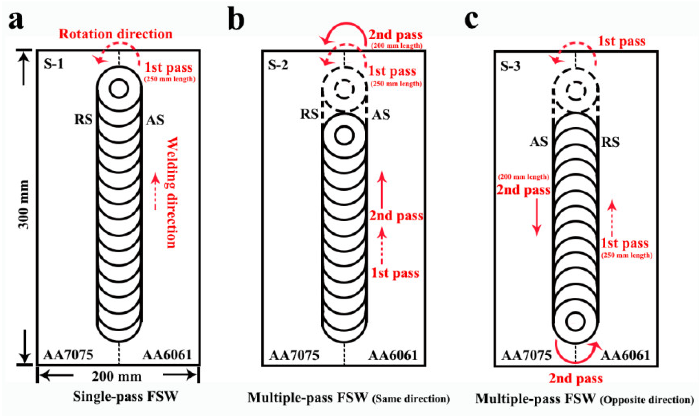
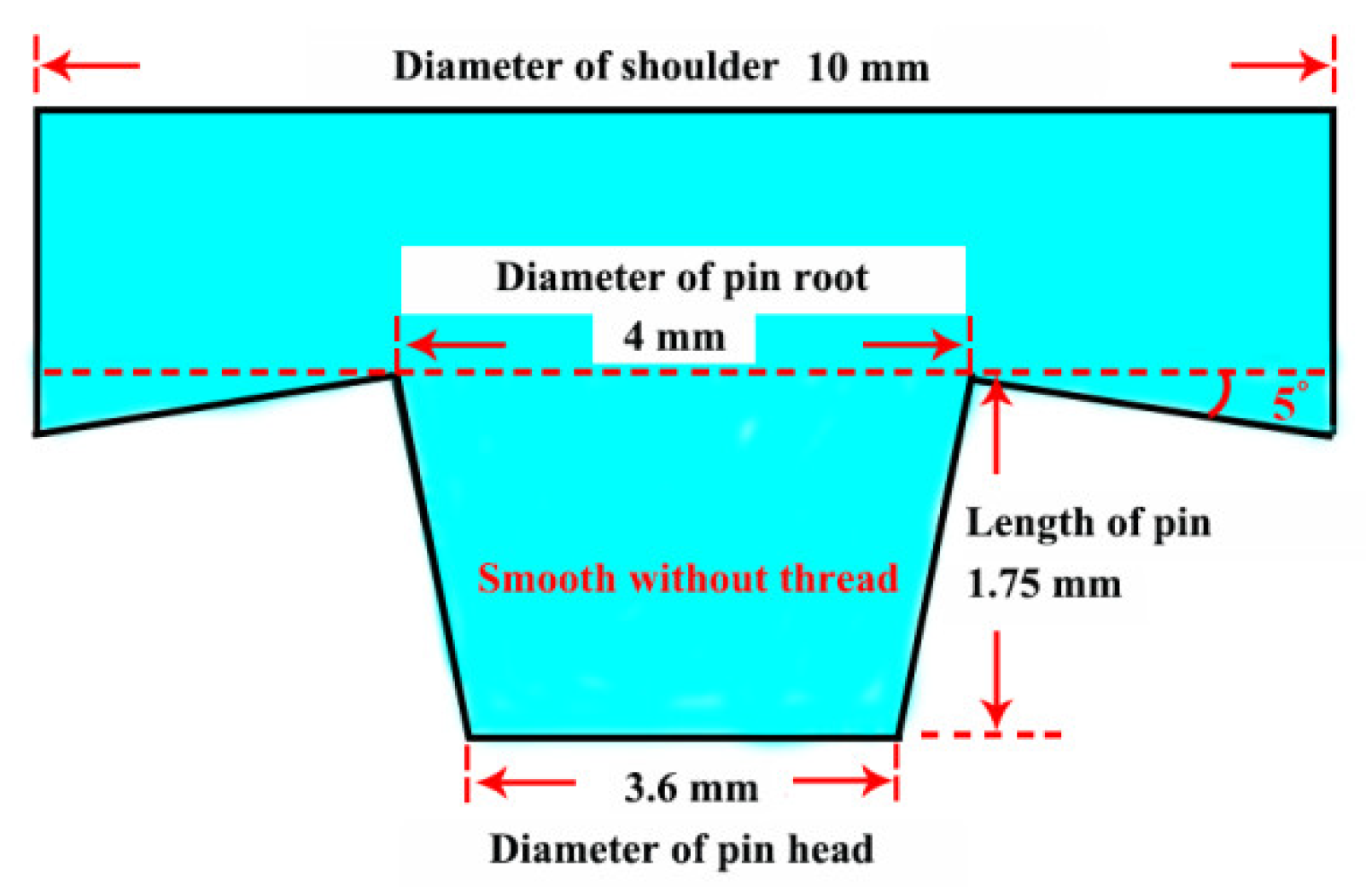
2. Materials and Methods

Cold-rolled AA6061 and AA7075 sheets of 2 mm thickness were selected as the BM and all aluminum sheets were artificially aged. The chemical compositions of the AA6061 and AA7075 alloys are listed in Table 1. The schematic diagrams of single-pass and multiple-pass FSW are drawn as shown in Figure 1. The AA6061 (placed on the AS) and AA7075 were first friction stir welded using a single-pass (namely, the first pass shown in Figure 1a), then a second overlapping pass was conducted with the welding direction of the second overlapping pass being the same as (Figure 1b) or opposite to (Figure 1c) the first pass. The length of the first pass was 250 mm while that of second overlapping pass was 200 mm. In this work, the sample fabricated by the single-pass FSW is denoted as S-1, while those fabricated by the multiple-pass FSW using both the same and opposite welding directions are denoted as S-2 and S-3, respectively. An H13 stir tool was employed for the single-pass and multiple-pass FSW. The shoulder was concave with a 10 mm diameter and the pin was conical with a 1.75 mm length (the root/head diameter of the pin was 4 mm/3.6 mm, respectively), and the schematic diagram of this stir tool is shown in Figure 2. All the FSW passes were performed under the same welding conditions, and the detailed welding parameters are illustrated in Table 2.
The microstructural characteristics in the NZ of the single-pass and multiple-pass FSW joints were analyzed systematically. The morphologies of grains were observed using optical microscopy (OM, Olympus equipment: DSX-500, Tokyo, Japan) and electron back-scattered diffraction (EBSD, FEI equipment: Quanta-600, Portland, OR, USA). Meanwhile, the distribution of elements and precipitates and/or particles were detected using scanning electron microscopy (SEM, FEI equipment: Quanta-600, Portland, OR, USA) and transmission electron microscopy (TEM, FEI equipment: Tecnai-G20, Portland, OR, USA). The samples for the OM, SEM, and TEM were cut in the middle section of the NZ. The OM and SEM samples were first mechanically polished and then etched with Keller’s reagent for 15 to 30 s (HF: 2 mL, HCL: 3 mL, HNO3: 5 mL and H2O: 190 mL). The TEM foils were jet electro-polished at −25 °C using a nitric acid-methanol solution (HNO3: 350 mL and CH3OH: 150 mL). The EBSD surfaces were electro-polished with a perchloric acid–ethanol solution (HCLO4: 50 mL and C2H5OH: 450 mL), and a 0.3 μm scanning step of the EBSD was utilized, with the low-angle grain boundaries (LAGBs, 2° < θ < 15°) marked as grey lines while the high-angle grain boundaries (HAGBs, θ > 15°) were marked as black lines.
The mechanical properties of the NZ fabricated via single-pass and multiple-pass FSW were assessed using the Vickers hardness and tensile test. Vickers hardness testing was carried out along the centerline of the cross-section of the FSW joint, and the loading force, dwelling time and interval of testing point were 50 gf, 5 s and 0.5 mm, respectively. For the tensile test, the strain rate was maintained at 1 × 10⁻³ s−1, and the tensile strength of each sample was tested three times to obtain an average measurement. The tensile specimens were machined parallel to the welding direction inside the NZ, with a dimension of 20 mm in gauge length and 4 mm in gauge width.

3. Results and Discussion

Figure 3 exhibits the initial microstructures of the BM. Due to the cold-rolling deformation, the coarse grains of the AA6061/AA7075 alloys were elongated (Figure 3a,b), while numerous dislocations were also introduced into the aluminum matrix (Figure 3e,f). In addition, the artificial aging process contributed to the precipitation and thus, a high amount of nanoscale precipitates were observed (Figure 3c,d). For the AA6061 (i.e., 6000 series aluminum alloy), the nanoscale precipitates were the needle β′ (β″)-Mg2Si phase [14,15], while those for the AA7075 (i.e., 7000 series aluminum alloy) were the spherical η (η′)-MgZn2 phase [16,17,18]. The existence of the above fine phases led to a high level of precipitation strengthening in the BM.
The cross-sections of the single-pass and multiple-pass FSW joints are shown in Figure 4, where the AA6061 and AA7075 alloys were successfully joined and the macrostructure of the NZ varied dependent on the welding conditions. An “onion ring” is a typical feather of FSW [19]; however, no “onion ring” was found in the NZ for the S-1 sample (Figure 4a) and the AA6061/AA7075 boundary was relatively smooth (Figure 5a), indicating that the mixing of dissimilar materials during the single-pass FSW was insufficient [20,21,22]. In practice, the formation of an “onion ring” is related to the material flow [22,23,24]; if the materials cannot move around the tool for more than one revolution, then the mixture of materials is insufficient and the formation of an “onion ring” can be inhibited. By contrast, in this study the application of a second overlapping pass contributed to the mixing of the dissimilar materials and as a result, a distinct “onion ring” formed in the NZ of the S-2 and S-3 samples (Figure 4b,c), and the AA6061/AA7075 boundary in the “onion ring” also became tangled (Figure 5b,c).
Apart from analyzing the mixture of dissimilar materials, the distribution of the Zn, Mg and Cu elements was also scanned to illustrate the location of the AA6061/AA7075 alloys. For the S-1 and S-2 samples, the AA6061 was mainly located in the lower part of the NZ (Figure 5d,e), but by contrast, the AA6061 moved upward in the S-3 sample (Figure 5f). Based on results from our previous studies [21,22], the materials on the AS rotated around the stir tool and flowed downward to the retreating side (RS), therefore, the lower part of the NZ was occupied by the AA6061 after the single-pass FSW. As for the S-2 sample, the pattern of material flow remained unchanged due to the same welding direction being employed, hence, the relative position of the AA6061/AA7075 alloys was stable during the second overlapping pass. In comparison, the opposite welding direction used in the S-3 sample converted the AA7075 from the RS to the AS, the AA7075 flowed downward and pushed the AA6061 upward during the second overlapping pass, changing the relative position of the AA6061/AA7075.
The morphologies of the grains in the NZ were detected using the EBSD technique, and in comparison to the coarse and elongated grains of the initial BM, the grains in the NZ for the S-1 sample were fine and equiaxed (Figure 6a,b). In addition, the difference in the grain size between the AA6061 and AA7075 was not significant (no more than 0.2 μm), which indicates that the grain uniformity of the NZ was relatively high. Due to the application of a second overlapping pass, the grains in the NZ became finer in the S-2 and S-3 samples (Figure 6c–f). It is known that the heat input and plastic deformation caused by FSW contributes to the occurrence of dynamic recrystallization (DRX) [25,26,27], and that DRX not only leads to a refinement of grains but also to an increase of HAGBs [28]. Consequently, after single-pass FSW in this study, the grains in the NZ became finer (4.2/4.0 μm) and the fraction of the HAGBs reached 78% (Figure 7). Compared to the S-1 sample, the application of a second overlapping pass prolonged the DRX time and the DRX became sufficient. Sufficient DRX enhanced the grain refinement further, while the fraction of HAGBs increased to 81% in the S-2 sample and 89% in the S-3 sample.
It was also interesting to observe that reversing the welding direction of the second overlapping pass affected the efficiency of the grain refinement effect, with the grains of the S-3 sample (2.1/2.3 μm) being much smaller than those of the S-2 sample (3.4/3.5 μm). In general, the grain size of the NZ is controlled by both the FSW temperature and strain rate [29], and fine grains form at a low temperature when combined with a high strain rate. In the present work, a similar temperature of all the FSW passes was maintained due to the constant welding parameters that were used, and thus the FSW strain rate may be the key factor in the grain refinement results. The material flow during the FSW process can be divided into a horizontal flow and vertical flow [30]. The horizontal flow induces the materials’ transfer from the AS to the RS (or from the RS to the AS), and the vertical flow leads the materials to flow upward (or downward). Under the coupled impacts of both horizontal and vertical flow, in this study the AA6061 on the AS moved downward to the RS and the AA7075 filled the cavity left on the AS (Figure 4a and Figure 5d) for the S-1 sample. The relative position of the AA6061/AA7075 in the S-2 sample was similar to that in the S-1 sample, and only a small amount of AA7075 (which filled the AS during the first pass) flowed downward (Figure 4b and Figure 5e). This illustrates that the vertical flow during the second overlapping pass was relatively weak, and that the FSW strain rate used in the S-2 sample was mainly caused by the horizontal flow. By contrast, the vertical flow of the S-3 sample was significant, where the AA7075 moved downward and took the place of the AA6061 during the second overlapping pass. This implies that reversing the welding direction of the second overlapping pass enhanced the vertical flow, and that the enhanced vertical flow increased the FSW strain in the S-3 sample. Therefore, the grain refinement process observed in the S-3 sample was more effective than that in the S-2 sample. The enhanced vertical flow also promoted the mixing of dissimilar materials in the NZ, except for the formation of an “onion ring”, where some clamped regions were detected at the AA6061/AA7075 boundary of the S-3 sample (as shown in Figure 4c and Figure 5f).
Figure 8 shows the morphologies of the NZ observed by the TEM. For the S-1 sample, the density of dislocations in the NZ reduced dramatically due to the occurrence of DRX, and furthermore, the initial fine precipitates disappeared. The melting points of the fine precipitates (i.e., Mg2Si and MgZn2) were much lower than the FSW temperature [31,32], and thus most precipitates were dissolved during the single-pass FSW (Figure 8a,b). The heat input of the second overlapping pass was similar to that of the single-pass FSW which was also high enough for dissolving the Mg2Si and MgZn2, and therefore, the amount of precipitates remained small in the S-2 and S-3 samples (Figure 8c–f).
Aside from the dislocation decrease and precipitate dissolution, some rod and round particles remained in the aluminum matrix (Figure 9), and energy dispersive X-ray spectroscopy (EDS, FEI equipment: Quanta-600, Portland, OR, USA) was carried out to analyze the compositions. The remaining particles in the AA6061 were mainly in the Al-(FeCrMn)-Si phase (Figure 9a) while those in the AA7075 were in the Al-Cu-Fe phase (Figure 9b), and these particles were difficult to dissolve during the FSW on account of their high melting points [33,34,35]. It should be noted that the average size of the above particles was fine enough (less than 500 nm) after the single-pass FSW and that they were unable to be broken down further by the mechanical stirring of the second overlapping pass [6]. Overall, the influences of multiple-pass FSW on the evolution of dislocations, precipitates and remaining particles were minimal.
Another interesting phenomenon was detected under observation using Kernel average misorientation (KAM), as shown in Figure 10. The distribution of the Al-(FeCrMn)-Si and Al-Cu-Fe phases were relatively random in the matrix, while some remaining coarse precipitates could also be found on the grain boundary (the white color regions in the KAM image). References [36,37,38] reported that the grain boundary was the preferential position of Mg2Si and MgZn2 particles, and thus some precipitates may re-precipitate on the grain boundary and become coarsened during the cooling period of FSW, however, the amount of re-precipitation is limited.
The Vickers hardness profiles of the single-pass and multiple-pass FSW joints are shown in Figure 11a, showing that the hardness profiles were asymmetric due to the different mechanical properties between the AA6061 and AA7075 alloys. Compared with the initial BM, the NZ was softened despite the significant grain refinement. During the FSW, the precipitation and dislocation strengthening effect was reduced due to the decreased number of dislocations and precipitates. Furthermore, the above loss in strength cannot be offset by the grain refinement [39,40,41], decreasing the hardness of the NZ. In contrast to the S-1 sample, the hardness of the NZ slightly increased after the second overlapping pass, which mainly arose as a result of the finer grains in the S-2/S-3 sample. Figure 11b shows the tensile properties of the NZ fabricated via the single-pass and multiple-pass FSW, and similar to the results for hardness, the NZ was enhanced after a second overlapping pass. Compared with the S-1 sample, the yield strength (YS) was elevated from 226 MPa to 235 and 277 MPa for the S-2 and S-3 samples, respectively, while a 3% and 7% increase in ultimate tensile strength (UTS) was also observed in the S-2 and S-3 samples, respectively. The strengthening of the S-2 and S-3 samples is attributed to not only the grain refinement but also to the mixture of dissimilar materials in the AA6061/AA7075 alloys. It has already been reported that the mixing of the dissimilar materials induced additional mechanical interlocking, which was beneficial for increasing the tensile strength [42]. Reversing the welding direction of the second overlapping pass improved the efficiency of the grain refinement and the dissimilar materials mixture further, and as a consequence, the S-3 sample exhibited the highest tensile strength among all the FSW samples.

4. Conclusions

AA6061 and AA7075 alloys were joined by using single-pass and multiple-pass FSW techniques, then the impacts of a second overlapping pass and its welding direction, on the characteristics of the NZ, were researched and the results are summarized as follows:
(1)
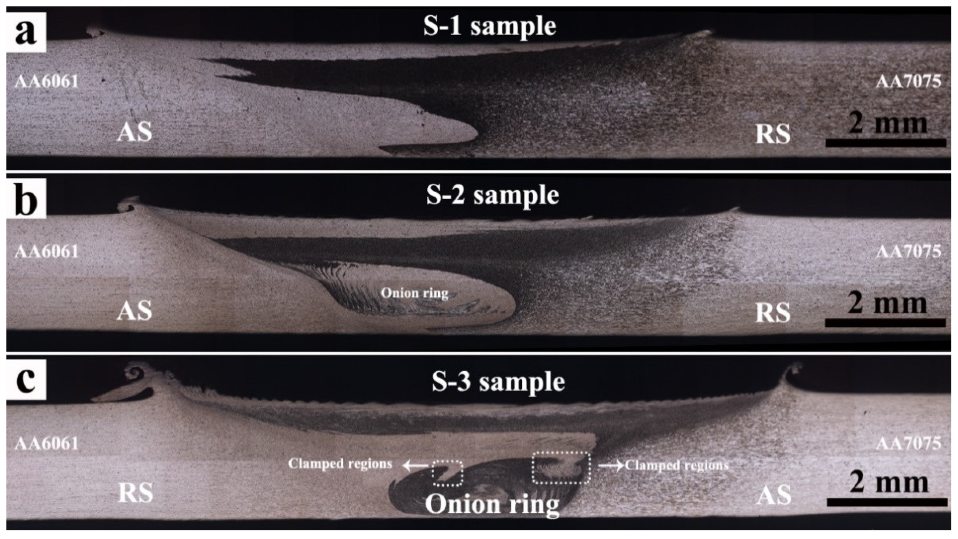
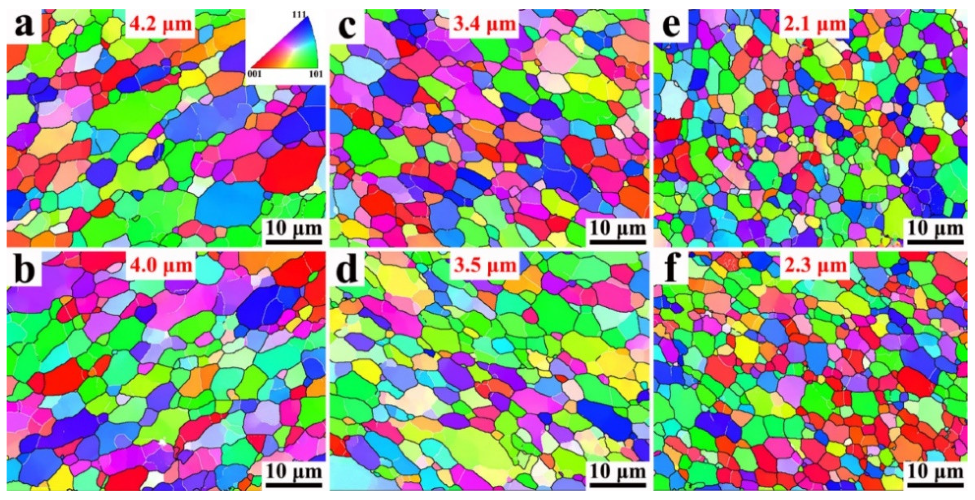
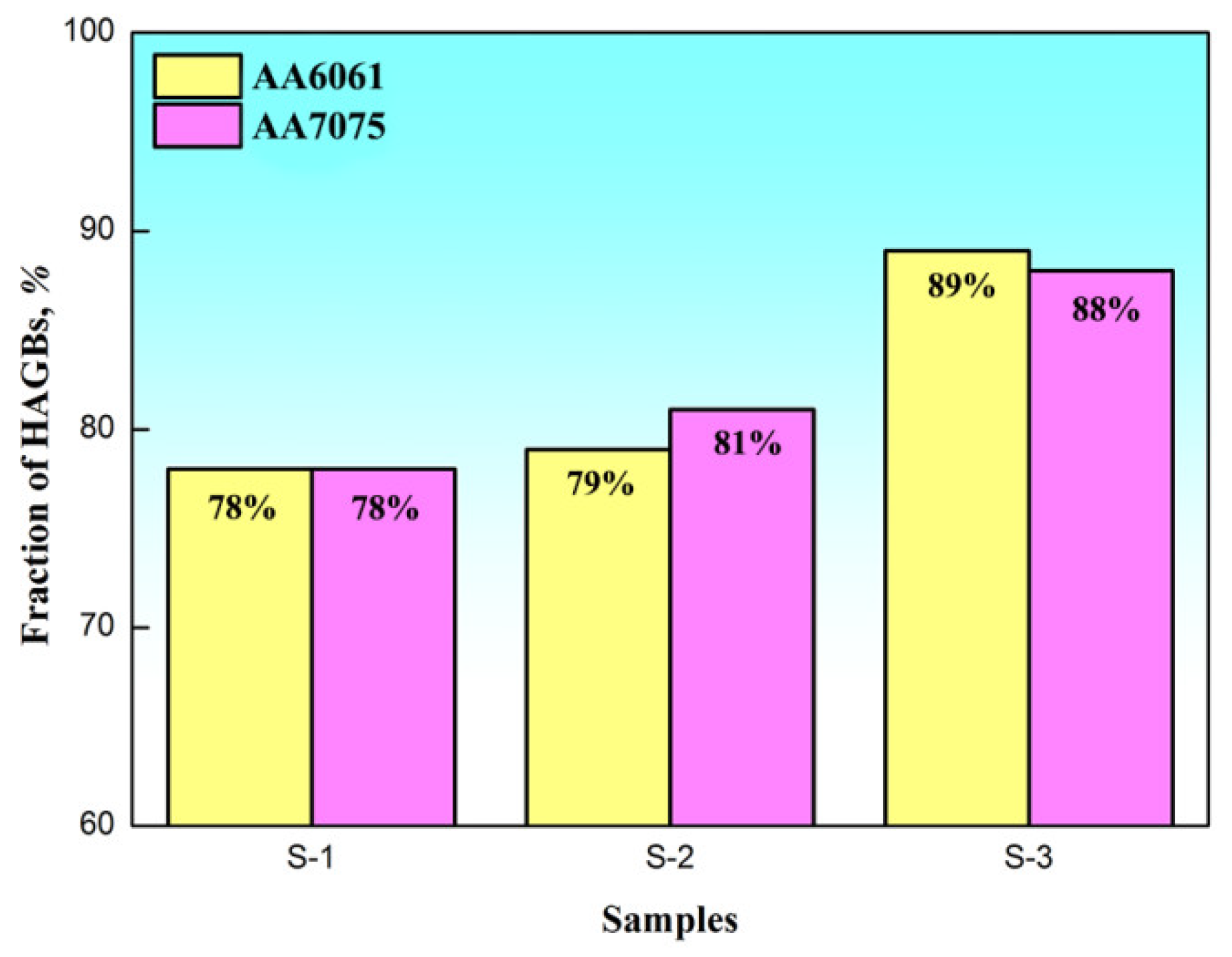
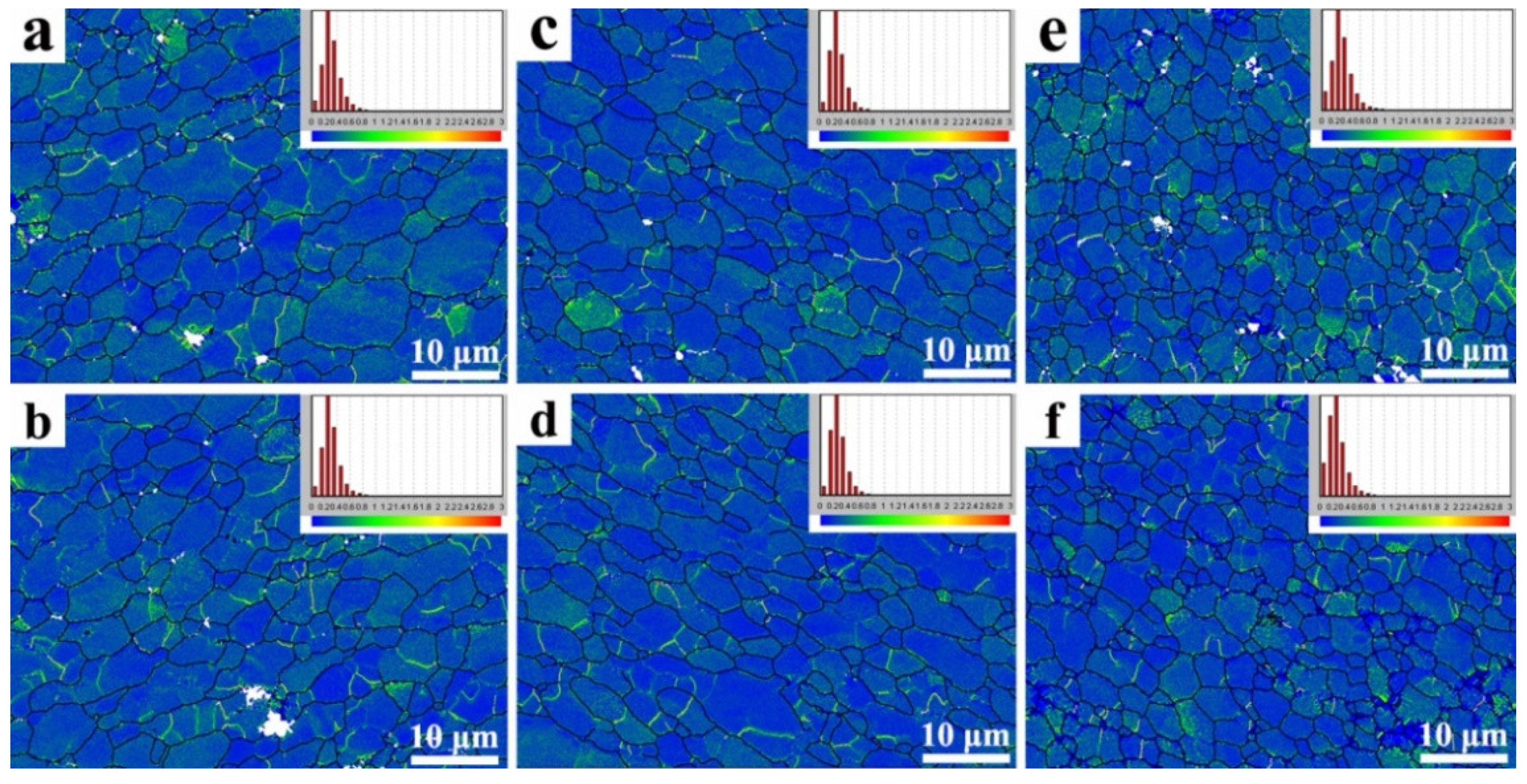
Compared with single-pass FSW, the DRX time was prolonged with the application of a second overlapping pass, and sufficient DRX during the multiple-pass FSW led to finer grains (20% decrease in average grain size) with increased HAGBs (2% increase in fraction) in the NZ. Additionally, reversing the welding direction of the second overlapping pass enhanced the vertical flow of materials, increasing the FSW strain in the NZ. Consequently, the grain refinement and mixing of dissimilar materials during the second overlapping pass was significant, with the grains becoming further refined from 4.2 μm to 2.1 μm.
(2)
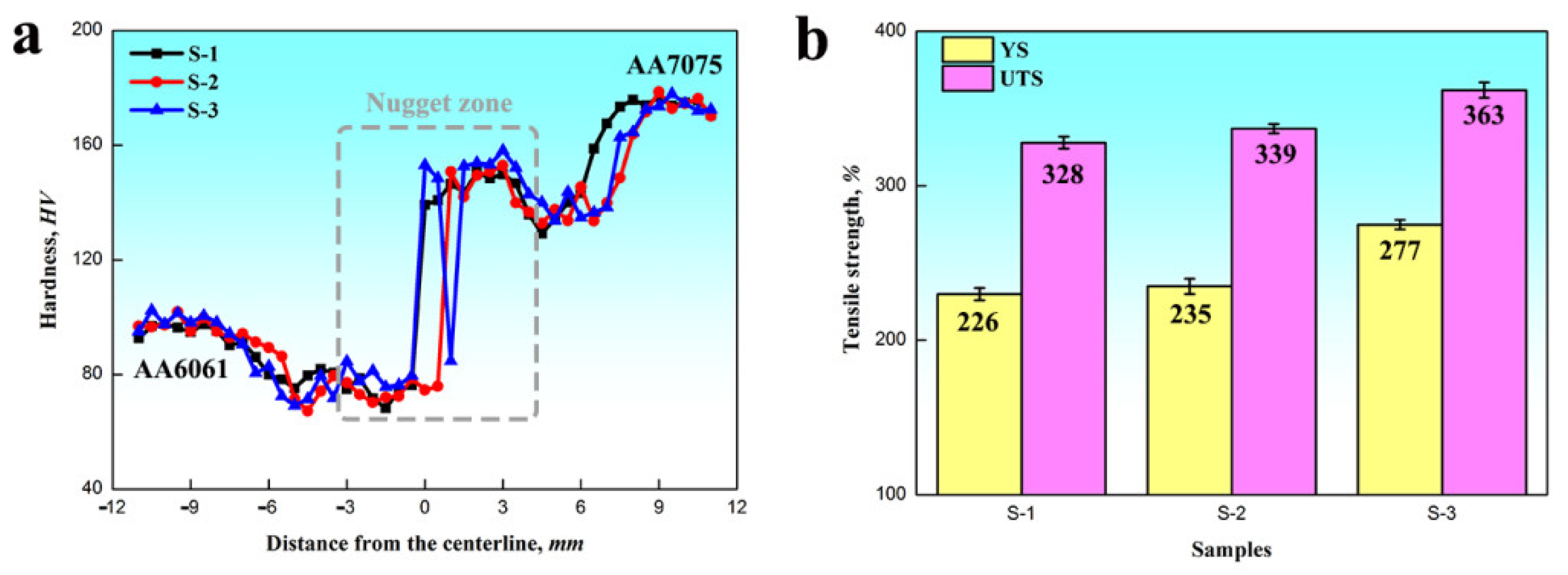
In comparison to the single-pass FSW, the NZ was strengthened after the second overlapping pass, which was caused by both the grain refinement and the mechanical interlocking of the AA6061/AA7075. A 3% increase was observed in both yield strength and ultimate tensile strength. Moreover, the NZ fabricated via the multiple-pass FSW with an opposite welding direction showed the highest tensile strength among all FSW samples, and the yield strength and ultimate tensile strength was increased by more than 50/30 MPa by conducting a second overlapping pass.

Author Contributions

Conceptualization, Y.C. and F.Z.; methodology, Y.C.; investigation, Y.C.; writing—original draft preparation, Y.C.; writing—review and editing, Z.C. and H.D.; project administration, Y.C.; funding acquisition, Y.C. All authors have read and agreed to the published version of the manuscript.

Funding

This research was funded by the National Natural Science Foundation of China (Grant No.52005090), Natural Science Foundation of Liaoning Province (Grant No.2020-BS-051), Fundamental Research Funds for the Central Universities of China (Grant No.N2103012) and National Defense Key Disciplines Laboratory of Light Alloy Processing Science and Technology, Nanchang Hangkong University (Grant No.EG202080409).

Data Availability Statement

Data are contained within the article.

Acknowledgments

Thanks for the technical support of Yuqing Mao, who is working in the National Defense Key Disciplines Laboratory of Light Alloy Processing Science and Technology, Nanchang Hangkong University.

Conflicts of Interest

The authors declare no conflict of interest.

References

  1. Thomas, W.M.; Nicholas, E.D. Friction stir welding for the transportation industries. Mater. Des. 1997, 18, 269–273. [Google Scholar] [CrossRef]
  2. Flores, A.O.V.; Kennedy, A.C.; Murr, A.L.E.; Brown, A.D.; Pappu, A.S.; Nowak, A.B.M.; McClure, A.J.C. Microstructural issues in a friction stir welded aluminum alloy. Scripta Mater. 1998, 38, 703–708. [Google Scholar] [CrossRef]
  3. Rhodes, C.G.; Mahoney, M.W.; Bingel, W.H.; Spurling, R.A.; Bampton, C.C. Effects of friction stir welding on microstructure of 7075 aluminum. Scripta Mater. 1997, 36, 69–75. [Google Scholar] [CrossRef]
  4. Qian, Q.; Su, Y.S.; Cao, H.; Zhang, D.; Ouyang, Q.B. Effect of post-weld heat treatment on double-sided friction stir welded joint of 120 mm ultra-thick SiCp/Al composite plates. Mater. Charact. 2020, 169, 110668. [Google Scholar]
  5. Chen, Y.; Jiang, Y.F.; Zhang, F.H.; Ding, H.; Zhao, J.W.; Ren, Z.H. Water Cooling Effects on the Microstructural Evolution and Mechanical Properties of Friction-Stir-Processed Al-6061 Alloy. Trans. Indian Inst. Met. 2018, 71, 3077–3087. [Google Scholar] [CrossRef]
  6. Chen, Y.; Ding, H.; Li, J.Z.; Cai, Z.H.; Zhao, J.W.; Yang, W.J. Influence of multi-pass friction stir processing on the microstructure and mechanical properties of Al-5083 alloy. Mater. Sci. Eng. A 2016, 650, 281–289. [Google Scholar] [CrossRef]
  7. Zhou, N.; Song, D.F.; Qi, W.J.; Li, X.Z.; Zou, J.; Attallah, M.M. Influence of the kissing bond on the mechanical properties and fracture behaviour of AA5083-H112 friction stir welds. Mater. Sci. Eng. A 2018, 719, 12–20. [Google Scholar] [CrossRef] [Green Version]
  8. Leal, R.M.; Loureiro, A. Effect of overlapping friction stir welding passes in the quality of welds of aluminium alloys. Mater. Des. 2008, 29, 982–991. [Google Scholar] [CrossRef]
  9. Cui, G.R.; Ni, D.R.; Ma, Z.Y.; Li, S.X. Effects of Friction Stir Processing Parameters and In Situ Passes on Microstructure and Tensile Properties of Al-Si-Mg Casting. Metall. Mater. Trans. A 2014, 45, 5318–5331. [Google Scholar] [CrossRef]
  10. Muribwathoho, O.; Msomi, V.; Mabuwa, S.; Motshwanedi, S.S. Impact of multi-pass friction stir processing on microhardness of AA1050/AA6082 dissimilar joints. Mater. Today Proc. 2021, 46, 651–657. [Google Scholar] [CrossRef]
  11. El-Rayes, M.M.; El-Danaf, E.A. The influence of multi-pass friction stir processing on the microstructural and mechanical properties of Aluminum Alloy 6082. J. Mater. Process. Tech. 2012, 212, 1157–1168. [Google Scholar] [CrossRef]
  12. Brown, R.; Tang, W.; Reynolds, A.P. Multi-pass friction stir welding in alloy 7050-T7451: Effects on weld response variables and on weld properties. J. Mater. Process. Tech. 2009, 513, 115–121. [Google Scholar] [CrossRef]
  13. Msomi, V.; Mabuwa, S. Analysis of material positioning towards microstructure of the friction stir processed AA1050/AA6082 dissimilar joint. Adv. Ind. Manuf. Eng. 2020, 1, 100002. [Google Scholar] [CrossRef]
  14. Yu, H.L.; Su, L.H.; Lu, C.; Tieu, K.; Li, H.J.; Li, J.T. Enhanced mechanical properties of ARB-processed aluminum alloy 6061 sheets by subsequent asymmetric cryorolling and ageing. Mater. Sci. Eng. A 2016, 674, 256–261. [Google Scholar] [CrossRef] [Green Version]
  15. Janadaghi, M.R.; Pouraliakbar, H.; Saboori, A.; Hong, S.I.; Pavese, M. Comparative insight into the interfacial phase evolutions during solution treatment of dissimilar friction stir welded AA2198-AA7475 and AA2198-AA6013 aluminum sheets. Materials 2020, 14, 1290. [Google Scholar] [CrossRef] [PubMed]
  16. Guo, W.; Guo, J.Y.; Wang, J.D.; Yang, M.; Li, H.; Wen, X.Y.; Zhang, J.W. Evolution of precipitate microstructure during stress aging of an Al–Zn–Mg–Cu alloy. Mater. Sci. Eng. A 2015, 634, 167–175. [Google Scholar] [CrossRef]
  17. Jandaghi, M.R.; Pouraliakbar, H.; Hong, S.I.; Pavese, M. Grain bounaary transition associated intergranular failure analysis at TMAZ/SZ interface of dissimilar AA7475-AA2198 joints by friction stir welding. Mater. Lett. 2020, 280, 128557. [Google Scholar] [CrossRef]
  18. Jandaghi, M.R.; Badini, C.; Pavese, M. Dissimilar friction stir welding of AA2198 and AA7475: Effect of solution treatment and aging on the microstructure and mechanical strength. J. Manuf. Process. 2020, 57, 712–724. [Google Scholar] [CrossRef]
  19. Krishnan, K.N. On the formation of onion rings in friction stir welds. Mater. Sci. Eng. A 2002, 327, 246–251. [Google Scholar] [CrossRef]
  20. Liu, X.C.; Sun, Y.F.; Morisada, Y.; Fujii, H. Dynamics of rotational flow in friction stir welding of aluminium alloys. J. Mater. Process. Tech. 2018, 252, 643–651. [Google Scholar] [CrossRef]
  21. Chen, Y.; Wang, H.; Li, H.Y.; Ding, H.; Zhao, J.W.; Zhang, F.H. Investigation into the Dissimilar Friction Stir Welding of AA5052 and AA6061 Aluminum Alloys Using Pin-Eccentric Stir Tool. Metals 2019, 9, 718. [Google Scholar] [CrossRef] [Green Version]
  22. Chen, Y.; Wang, H.; Wang, X.Y.; Ding, H.; Zhao, J.W.; Zhang, F.H.; Ren, Z.H. Influence of tool pin eccentricity on microstructural evolution and mechanical properties of friction stir processed Al-5052 alloy. Mater. Sci. Eng. A 2019, 739, 272–276. [Google Scholar] [CrossRef]
  23. Li, Y.; Murr, L.E.; McClure, J.C. Solid-state flow visualization in the friction stir welding of 2024 Al to 6061 Al. Scripta Mater. 1999, 40, 1041–1046. [Google Scholar] [CrossRef]
  24. Guerra, M.; Schmidt, C.; McClure, J.C.; Murr, L.E.; Nunes, A.C. Flow patterns during friction stir welding. Mater. Charact. 2002, 49, 95–101. [Google Scholar] [CrossRef] [Green Version]
  25. Mishra, R.; Ma, Z.Y. Friction stir welding and processing. Mater. Sci. Eng. R. 2005, 50, 1–78. [Google Scholar] [CrossRef]
  26. Jata, K.V.; Semiatin, S.L. Continuous dynamic recrystallization during friction stir welding of high strength aluminum alloy. Scripta Mater. 2000, 43, 743–749. [Google Scholar] [CrossRef]
  27. Murr, L.E.; Liu, G.; McClure, J.C. Dynamic recrystallization in friction stir welding of aluminum alloy 1100. J. Mater. Sci. Lett. 1997, 16, 1081–1803. [Google Scholar] [CrossRef]
  28. Luo, X.C.; Kang, L.M.; Liu, H.L.; Li, J.Z.; Liu, Y.F.; Zhang, D.T.; Chen, D.L. Enhancing mechanical properties of AZ61 magnesium alloy via friction stir processing: Effect of processing parameters. Mater. Sci. Eng. A 2020, 797, 139945. [Google Scholar] [CrossRef]
  29. Azimzadegan, T.; Serajzadeh, S. An Investigation into Microstructures and Mechanical Properties of AA7075-T6 during Friction Stir Welding at Relatively High Rotational Speeds. J. Mater. Eng. Perform. 2010, 19, 1256–1263. [Google Scholar] [CrossRef]
  30. Liu, X.C.; Wu, C.S. Material flow in ultrasonic vibration enhanced friction stir welding. J. Mater. Process. Tech. 2015, 225, 32–44. [Google Scholar] [CrossRef]
  31. Sun, Z.P.; Yang, X.Q.; Li, D.X.; Cui, L. The local strength and toughness for stationary shoulder friction stir weld on AA6061-T6 alloy. Mater. Charact. 2016, 111, 114–121. [Google Scholar] [CrossRef]
  32. Li, D.X.; Yang, X.Q.; Cui, L.; He, F.Z.; Zhang, X. Investigation of stationary shoulder friction stir welding of aluminum alloy 7075-T651. J. Mater. Process. Tech. 2015, 222, 391–398. [Google Scholar] [CrossRef]
  33. Gavras, A.G.; Lado, D.A.; Champagne, V.K.; Warren, R.J. Effects of processing on microstructure evolution and fatigue crack growth mechanisms in cold-spray 6061 aluminum alloy. Int. J. Fatigue 2018, 110, 49–62. [Google Scholar] [CrossRef]
  34. Sato., Y.S.; Urata, M.; Kokawa, H. Parameters controlling microstructure and hardness during friction-stir welding of precipitation-hardenable aluminum alloy 6063. Metall. Mater. Trans. A 2002, 33, 625–635. [Google Scholar] [CrossRef]
  35. Su, J.Q.; Nelson, T.W.; Mishra, R.; Mahoney, M. Microstructural investigation of friction stir welded 7050-T651 aluminium. Acta Mater. 2003, 51, 713–729. [Google Scholar] [CrossRef]
  36. Kumar, P.V.; Reddy, G.M.; Rao, K.S. Microstructure, mechanical and corrosion behavior of high strength AA7075 aluminum alloy friction stir welds-Effect of post weld heat treatment. Def. Technol. 2015, 11, 362–369. [Google Scholar] [CrossRef] [Green Version]
  37. Sharma, C.; Dwivedi, D.K.; Kumar, P. Effect of post weld heat treatments on microstructure and mechanical properties of friction stir welded joints of Al-Zn-Mg alloy AA7039. Mater. Des. 2013, 43, 134–143. [Google Scholar] [CrossRef]
  38. Chandra, T.; Tsuzaki, K.; Militzer, M.; Ravindran, C. Grain growth behavior and mechanical properties of the friction stir welded zone of 7055 Al alloy followed by post weld heat treatment. Mater. Sci. Forum 2007, 239–534, 4087–4092. [Google Scholar]
  39. Feng, X.; Liu, H.; Babu, S.S. Effect of grain size refinement and precipitation reactions on strengthening in friction stir processed Al–Cu alloys. Scripta Mater. 2011, 65, 1057–1060. [Google Scholar] [CrossRef]
  40. Zande, J.; Sandstorm, R. One parameter model for strength properties of hardenable aluminium alloys. Mater. Des. 2008, 29, 1540–1548. [Google Scholar] [CrossRef]
  41. Kalinenko, A.; Kim, K.; Vysotskiy, I.; Zuiko, I.; Malopheyev, S.; Mironov, S.; Kaibyshev, R. Microstructure-strength relationship in friction-stir welded 6061-T6 aluminum alloy. Mater. Sci. Eng. A 2020, 793, 139858. [Google Scholar] [CrossRef]
  42. Ji, S.D.; Meng, X.C.; Liu, Z.L.; Huang, R.F.; Li, Z.W. Dissimilar friction stir welding of 6061 aluminum alloy and AZ31 magnesium alloy assisted with ultrasonic. Mater. Lett. 2017, 201, 173–176. [Google Scholar] [CrossRef]
Figure 1. The schematic diagrams of (a) single-pass FSW; multiple-pass FSW with (b) the same and (c) the opposite welding direction.
Metals 11 01506 g001
Figure 2. The schematic diagram of the stir tool used in this work.
Metals 11 01506 g002
Figure 3. The microstructures of the initial BM: the grain morphology of (a) AA6061 and (b) AA7075; the precipitate distribution of (c) AA6061 and (d) AA7075; the dislocation characteristics of (e) AA6061 and (f) AA7075. (The TEM was observed using the bright field mode).
Metals 11 01506 g003
Figure 4. The cross-sections of dissimilar AA6061/AA7075 joints fabricated via (a) single-pass FSW, and multiple-pass FSW using (b) the same and (c) the opposite welding direction.
Metals 11 01506 g004
Figure 5. The AA6061/AA7075 boundary in the “onion ring” of (a) S-1, (b) S-2 and (c) S-3 samples observed by OM; the relative position of AA6061/AA7075 in (d) S-1, (e) S-2 and (f) S-3 samples detected by SEM.
Metals 11 01506 g005
Figure 6. The grain morphologies in the NZ of (a) AA6061 and (b) AA7075 for the S-1 sample; (c) AA6061 and (d) AA7075 for the S-2 sample; (e) AA6061 and (f) AA7075 for the S-3 sample.
Metals 11 01506 g006
Figure 7. The fraction of high angle grain boundaries (HAGBs) of the NZ for single-pass and multiple-pass FSW samples.
Metals 11 01506 g007
Figure 8. The TEM images in the NZ of (a) AA6061 and (b) AA7075 for the S-1 sample; (c) AA6061 and (d) AA7075 for the S-2 sample; (e) AA6061 and (f) AA7075 for the S-3 sample. (The TEM was observed using the bright field mode).
Metals 11 01506 g008
Figure 9. The EDS results of remaining particles in the NZ of (a) AA6061 and (b) AA7075 for the S-1 sample. (The TEM was observed using the bright field mode).
Metals 11 01506 g009
Figure 10. Kernel average misorientation micrograph and its corresponding histogram in the NZ of (a) AA6061 and (b) AA7075 for the S-1 sample; (c) AA6061 and (d) AA7075 for the S-2 sample; (e) AA6061 and (f) AA7075 for the S-3 sample.
Metals 11 01506 g010
Figure 11. The results of (a) Vickers hardness and (b) tensile strength of the single-pass and multiple-pass FSW samples.
Metals 11 01506 g011
Table 1. Chemical compositions (wt. %) of the studied AA6061 and AA7075 alloys.
AA6061MgSiCuMnFeCrAl
1.110.650.190.220.690.28Bal
AA7075ZnMgCuMnFeCrAl
5.722.361.650.220.310.24Bal
Table 2. Experimental welding parameters for single-pass and multiple-pass FSW.
SampleRotational SpeedWelding
Speed
Plunge DepthTilt AnglePass
Number
Direction of Second Pass
S-11200 rpm200 mm/min0.2 mm2.5°1-
S-21200 rpm200 mm/min0.2 mm2.5°2Same as the first pass
S-31200 rpm200 mm/min0.2 mm2.5°2Opposite to the first pass
Publisher’s Note: MDPI stays neutral with regard to jurisdictional claims in published maps and institutional affiliations.

