Abstract
The flow behavior in the mold has a considerable influence on the final product quality of the strand. In this paper, the variation of flow field, level fluctuation, and liquid slag distribution was analyzed by a hydraulic modeling experiment of a high-speed billet continuous casting mold with and without consideration of hydrostatic pressure and a solidified shell. The results indicate that a mold with hydrostatic pressure and a solidified shell possesses an impact depth shallower by 10–30 mm, level fluctuation greater by 3–15%, and more active liquid slag layer at different casting speeds than a mold without them. Moreover, the results of the hydraulic modeling with hydrostatic pressure and a solidified shell agree well with those of the numerical simulation. Therefore, the mold flow behavior modeled with hydrostatic pressure and a solidified shell is closer to the actual behavior than that obtained by models without them. The method in this paper contributes to improving the accuracy of the hydraulic modeling experiment and establishing a foundation for further study of continuous casting.
1. Introduction
Continuous casting, wherein molten steel is moved through a mold, is a finishing process that can improve the quality of the molten steel. The process is accompanied by a series of complicated physical and chemical interactions inside the mold. Among them, the fluid flow in the mold plays a crucial role in promoting the flotation and removal of inclusions [1], preventing slag entrapment [2] and molten steel leakage [3], promoting uniform growth of the solidified shell [4], and producing a high-quality strand [5,6]. To investigate the fluid flow in the mold, numerical simulations [7,8] and hydraulic modeling [9] are the prevailing methods, where both methods are interrelated and complementary. Therefore, hydraulic modeling experiments were used herein to study the flow field in the mold of high-speed billet continuous casting. These experiments were intended to provide a deeper insight into the flow behavior and to assist in optimizing the process parameters and improving the strand quality.
Extensive previous research has employed hydraulic modeling experiments to successfully investigate fluid flow phenomena in the mold region of the continuous casting process. Szekely et al. [10] compared the straight-through and radial submerged entry nozzle (SEN) flow fields in a mold via flow visualization and velocity field measurement in a hydraulic modeling experiment. They found that the flow field of the mold using radial SEN was more conducive to inclusion flotation. Gupta et al. [11,12,13] researched fluid fluctuation at the meniscus of a mold under different SEN parameters and the asymmetry and oscillation inside the mold via hydraulic modeling experiments [12,13]. They thus obtained a linear relation between the dimensionless amplitude and the Froude number [11], and explained the vortex formation and bubble entrainment [13]. Jeon et al. [14] researched fluid oscillation inside the mold and the meniscus level fluctuation, and analyzed the vortex generation mechanism in the mold using a hydraulic modeling experiment with a funnel-shaped mold. Jin et al. [15] conducted hydraulic modeling experiments with a solidified shell to study the fluid flow in a slab mold, showing that the level fluctuation is more intense, the liquid surface velocity is higher, and the distribution uniformity of the slag layer is worse when considering the solidified shell. Zhang et al. [16] analyzed the wave amplitude, frequency, and components of fluctuation at the meniscus via fast Fourier transform and wavelet entropy in a water model of the slab. Although a substantial number of hydraulic modeling experiments have been run to investigate fluid flow in the mold, there remain deficiencies among them. First, most of the hydraulic modeling experiments have been carried out while neglecting the solidified shell. In an actual continuous casting process, however, the partially-molten steel converted into the solidified shell will not participate in fluid movement. Therefore, hydraulic modeling experiments neglecting the solidified shell will suffer some inherent imprecision. To simulate a solidified shell, Jin et al. [15] established a hydraulic model of the slab mold that incorporated a tapered solid shell uniformly covered with small holes. This model is closer to the actual continuous casting mold and has obtained results that are relatively more accurate. This hydraulic model still possesses shortcomings, however, owing to the fact that it disregards the effect of hydrostatic pressure along the direction of the continuous casting mold height on the solidified shell design. As a result, some differences still exist between these experimental results and the actual conditions.
In addition to performing a single physical simulation, a number of mathematical models were established to study the flow, heat transfer, and solidification of molten steel in the mold, and the results of the two methods were compared to verify the reliability of the study [17]. Lan et al. [18] quantitatively measured the fluid velocity and turbulence in the mold using laser Doppler velocity measurement technology, and compared the results with those of the numerical simulation in a hydraulic modeling experiment of a billet mold. Ramos-Banderas et al. [19] studied unsteady fluid flow in the mold using a hydraulic modeling experiment, whereby fluid oscillation and an asymmetric flow field were found in the vertical direction of the mold, and these results were compared with those of numerical simulation. Miranda et al. [20] studied the free surface of the mold under various water flow rates and SEN insertion depths by establishing a mold physical model, and compared these results with those of numerical simulation. Liu et al. [21] used an Eulerian multiphase-flow model to predict the argon–steel–slag three-phase flow, and the results were compared with those of a hydraulic modeling experiment. Except for the above mentioned shortcomings that previous hydraulic modeling experiments hardly consider hydrostatic pressure and a solidified shell, the majority of previously reported hydraulic modeling experiments and numerical simulation for the continuous casting mold have been operated with conventional casting speeds (about 3.0 m/min), and few reports involve the investigation of high-speed casting molds.
In view of the aforementioned deficiencies, hydraulic modeling experiments of a high-speed billet continuous casting mold considering a solidified shell and hydrostatic pressure were carried out in this paper, and attaining more accurate and faithful results. This paper mainly investigates the flow behavior in the billet mold, and the corresponding experimental results were compared with those of hydraulic modeling experiments without a solidified shell, as well as to numerical simulations, and the corresponding differences were investigated and analyzed.
2. Hydraulic Model and Experiment Method
2.1. Establishment of Hydraulic Model
The hydraulic modeling experiment was administered based on the similarity principle. The flow of molten steel in the mold is mainly affected by inertia force, gravitational force, viscous force, and surface tension, and three dimensionless numbers can be obtained by the ratio of four sorts of forces each. They are Reynolds number (Re), Froude number (Fr), and Weber number (We), respectively. However, considering the complexity of actual continuous casting mold, it is hardly possible to keep every force equal between hydraulic model and prototype during setting up hydraulic model. Therefore, the number that is dominant should be chosen and kept equal, where the number is chosen according to different research objectives.
This paper mainly focuses on the flow behavior in the billet mold, and the appurtenant mold parameters are shown in Table 1. Aimed at this purpose, geometric similarity and dynamic similarity are two necessary similarity conditions and need to be taken into account. In pursuit of ensuring dynamic similarity, the Re and Fr between prototype and hydraulic model should be equal, respectively. However, there is little prospect of satisfying two similar numbers to be absolutely equal at the same time in the actual operation. Notwithstanding, concerning hydraulic modeling experiment running, the fluid flow in the mold will be in the second self-modeling region at high speed casting speed and automatically achieve the similar situation between the prototype and hydraulic model. Thus, the viscous force-related Re can be ignored and only the gravity-related Fr needs to be equal.

Table 1.
Dimensions and parameters. SEN, submerged entry nozzle.
When Fr is equal, the geometric similarity can be selected for any proportion. On the basis of the requirement of precise modeling and observation of the fluid flow in the hydraulic model, the larger the proportion of geometric similarity, the better the modeling effect. Thus, this paper adopts a 1:1 geometric similarity proportion. As a consequence, the corresponding velocity ratio and volume flux ratio can be calculated by [15,22]
where g is the gravitational acceleration, and is generally 9.81 m/s2; lm and lp are the characteristic length of the model and prototype (m), respectively; vm and vp are the fluid velocity of the model and prototype (m/s), respectively; and Qm and Qp are the volume flux of the model and prototype (m3/s), respectively.
In addition, compared with the previous hydraulic models, we note that the solidified shell thickness in the continuous casting mold gradually augments with the increasing distance from the meniscus, and the corresponding solidification flux of the molten steel also alters along the casting direction. Therefore, to accurately represent the flow behavior in the mold, this paper established a hydraulic model of the mold that considers a solidified shell and a variation of the solidification flux by adding an extra multi-hole shell made of polymeric methyl methacrylate (PMMA) inside the hydraulic model in Figure 1 (mainly containing the tundish, mold, and data acquisition system). Here, the shell itself presented an inverted cone and was used to model the solidified shell in the continuous casting mold, and the small holes on the shell were used to realize the variation of the solidification flux. Therefore, the design of a multi-hole shell is crucial, especially for the distribution of small holes on the shell.
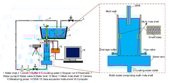
Figure 1.
Hydraulic modeling experiment device considering a solidified shell and varying solidification flux. SEN, submerged entry nozzle.
Here, the design of the multi-hole shell in Figure 1 comprised the following assumptions:
- (1)
- This paper only focused on the steady continuous casting process.
- (2)
- Hydraulic modeling was conducted under ambient temperature (about 300.15 K), regarding the parameters of the fluid as constant.
- (3)
- The solidified shell grows uniformly around the mold.
- (4)
- The influence of the arc structure on the solidified shell thickness was not considered, assuming the solidified shell increased linearly from the meniscus to the mold outlet.
- (5)
- The solidified shell thickness was 10 mm at the mold outlet.
- (6)
- The material thickness of the shell itself is 2 mm, and this paper will consider it into the part of the no solidified fluid. Therefore, the material thickness is much less than the size of the flowing region, and so it can be neglected.
- (7)
- The small size deviation caused by manual operation in the design of multi-hole shell is ignored.
2.2. Arrangement of Small Holes on Solidified Shell
In the hydraulic modeling experiments herein, with a solidified shell and changing solidification flux, water was used to simulate the molten steel. To prevent the fluid representing the molten steel already converted into the solidified shell from further participating in the flow field, it was essential to drain off the equivalent fluid according to the changing solidification flux at different heights along the mold. In this paper, the drainage of this part fluid is carried on by drilling small holes from top to bottom on the solidified shell. However, because of hydrostatic pressure existing in the direction of mold height, the drainage speed of holes is different, that is, hydrostatic pressure at the meniscus is at a minimum, and then the drainage rate of the corresponding hole is the slowest, yet when there is maximum hydrostatic pressure at the outlet of mold, then the drainage rate of corresponding hole is the fastest. Consequently, to ensure that the drainage flux of small holes in different distances from the meniscus of hydraulic model is equal to the genuine solidification flux, this paper has considered the significance of hydrostatic pressure when devising the distribution of small holes on the solidified shell, and the detailed design method of small holes is as follows:
(1) As shown in Figure 2, the thickness of the solidified shell at a certain cross section along the mold casting direction is determined by
where D is the thickness of the solidified shell at the cross section (mm); Doutlet is the thickness of the solidified shell at the mold outlet (10 mm); Z is the distance of the cross section from the mold meniscus (mm); and H is the effective height of the mold (mm).
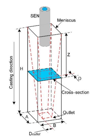
Figure 2.
The sketch diagram of selecting a cross section at the casting direction.
(2) Equation (5) shows the volume flux converted into the solidified shell from the meniscus to a certain solidified shell cross section of thickness D in Figure 2 along the casting direction of the mold:
where Q is the volume flux converted into the solidified shell at the cross section (ml/s); A and B are the width and thickness of the mold, respectively (mm); and v is the casting speed of the strand (mm/s). The specific derivation steps of Equation (5) are shown in Appendix A at the end of the paper.
(3) Before correctly distributing the small hole on the solidified shell, it is necessary to get the volume flux of the small hole. The relationship between the volume flux of a single small hole diameter d and the distance Z from the meniscus of the mold is given as
where Qhole is the volume flux of single hole with a diameter d, (ml/s); and a and b are two fixed values, and the units of them are and ml/s, respectively. The specific derivation steps of Equation (6) are shown in Appendix A.
It is noted that the distance Z in Equation (6) reflects the effect of hydrostatic pressure on the flow rate of a small hole. Because the value of hydrostatic pressure equals at the distance Z from the meniscus and, additionally, and g are fixed values in general, it is known that is directly proportional to . Therefore, we can reflect the effect of hydrostatic pressure using the distance Z obtained easily instead of .
In addition, the diameter d of the small hole herein was 1 mm. If it is too small, there will occur a capillary phenomenon that is not good to drain off the fluid and, conversely, the number of small holes will become so little that the solidified shell cannot be covered fully with small holes, and meaning the hydraulic model could not simulate normally the variation of solidification flux.
(4) On the basis of the abovementioned both volume flux Q and Qhole, this paper arranged the small holes on the solidified shell in detail. Considering the mold meniscus as the zero point of static pressure, a row of small holes was placed on the solidified shell at the interval Δh along the casting direction of the mold. As a consequence, together with Equations (4)–(6), the number of small holes Nn+1 at row n on the mold cross section at distance Zn+1 from the meniscus can be calculated by
where Nn+1 is the number of small holes around the circumference of the solidified shell at distance Zn+1 from the mold meniscus; n is the row number; and Δh is the interval between two adjacent rows. The value of Δh herein was 10 mm. Too small of a Δh will create too many small holes in the solidified shell, hindering the process; while too large of a Δh results in a hydraulic model that cannot faithfully simulate the variation of the solidification flux.
Using the method described, the arrangement of small holes on the solidified shell along the casting direction was designed, which is shown in Figure 3, and the small holes are perpendicular to the solidified shell.
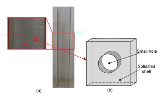
Figure 3.
The sketch diagram of the arrangement of small holes on the solidified shell: (a) photograph; (b) view of single hole.
2.3. Experimental Scheme
On the basis of the hydrostatic model established in the paper, an experimental strategy of hydraulic modeling at various casting speeds was proposed by adopting the SEN parameters determined through previous experiment in Table 1:
(1) Blue ink was used as a tracer to display the flow field in the mold. The flow field was thus recorded via a video recorder, whereupon the impact depth of the stream was measured from the video.
(2) The level fluctuation in the top surface of the mold was measured by a DJ800 multifunctional hydraulic monitoring system. The acquisition time interval was 0.02 s and the acquisition time was 300 s. The range of the measuring device was 0~10 cm and its accuracy was ±0.5%. The acquisition time interval was 0.02 s and the acquisition time was 300 s. Moreover, in the computer, three sorts of result data can be obtained by the measuring device, that is, 1/10 level fluctuation (the average of the first 1/10 measured data), 1/3 level fluctuation (the average of the first 1/3 measured data), and average level fluctuation (the average of all measured data), respectively. Because the straight through SEN was adopted in the hydraulic model experiment, the level fluctuation is generally low, and 1/3 level fluctuation and average level fluctuation cannot genuinely capture the level fluctuation. Therefore, the 1/10 level fluctuation was chosen to the standard. Then, for each working condition, five measurements were taken and their average value was chosen as the level fluctuation. The position at which each level fluctuation measurement was obtained is shown in Figure 4, and they are labeled points A–H.
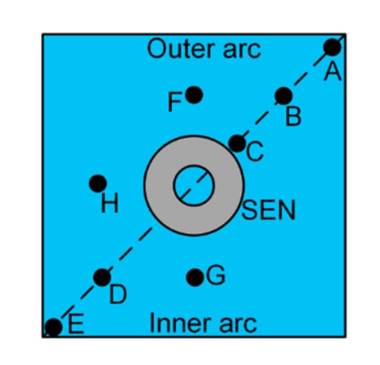
Figure 4.
The distribution of measuring points for level fluctuation on top surface.
(3) To simulate slag entrapment and liquid slag cover in the billet continuous casting mold, a mixed oil of mechanical pump oil and kerosene was used to simulate liquid slag in this paper, and the thickness of the mixed oil layer is 10 mm and other physical parameters are listed in Table 1. It is necessary that the viscosities of the liquids satisfy the following relation:
(4) The results of the hydraulic modeling experiment with a solidified shell and hydrostatic pressure were compared with those without them.
(5) In addition, a half geometric model of the billet continuous casting mold was established and meshed, whereupon a numerical simulation coupling fluid flow and solidification and heat transfer as well as species transport was carried out using the standard k-ε turbulence model in the Fluent14.0 commercial software; the corresponding governing equations are provided in the works of Zhang et al. [23] and Chen et al. [24]. The solution method was SIMPLE, and the time step was selected as 0.01 s. At the inlet of SEN, the velocity-inlet boundary condition was used. The inlet velocity was calculated through the mass conservation based on the casting speed. The inlet value of turbulent kinetic energy and the rate of turbulent energy dissipation were 0.00001 respectively. The pressure-outlet boundary condition was applied at the strand exit. The top free surface was set as zero shear stationary wall and heat insulation. At the symmetry plane, the normal velocity components and normal gradients of all other variables were assumed to be zero. At the strand surface, the heat transfer boundary condition was employed for the heat flux, which decreased along the casting direction. The strand was meshed using about 390,000 hexahedral cells, and the skewness and orthogonal quality of mesh are about 0.2–0.65 and 0.4–0.8, respectively. In this way, this paper compared the hydraulic modeling experimental results with those of the numerical simulation.
3. Results and Discussion
3.1. Fluid Flow in the Mold
The fluid flow inside the mold has a notable influence on phenomena such as inclusion flotation, top surface disturbance, and solidified shell growth. Therefore, this work presents the flow fields of the hydraulic modeling experiments with a solidified shell and hydrostatic pressure as well as without a solidified shell at four different casting speeds (Figure 5). It is clear that the flow fields of both model types are similar for the four casting speeds, and the stream inserted into the mold via the SEN diffuses gradually along the casting direction. Moreover, owing to the arc structure of the mold, the stream is closer to the inner arc, and the flow space between the stream and mold wall or solidified shell becomes smaller around the inner arc. As a consequence, the upward flow around the inner arc experiences increased wall resistance that reduces the upward flow speed, while the disturbance of the top surface of the inner arc decreases. The effects at the outer arc are the opposite. The primary difference between the two model types is that the overall diffusion range of the stream in the hydraulic modeling experiment with a solidified shell and hydrostatic pressure is smaller than that without a solidified shell. This is because, when considering a solidified shell, the volume of fluid flow inside the mold will continuously reduce and the resistance of the stream will increase during the downward movement. Therefore, the diffusion is not as adequate as that without the solidified shell.
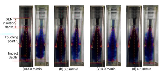
Figure 5.
Comparison of the flow field in the mold at various casting speeds obtained via the hydraulic modeling experiment without a solidified shell (left), and with a solidified shell and hydrostatic pressure (right). (a) 3.0 m/min; (b) 3.5 m/min; (c) 4.0 m/min; (d) 4.5 m/min.
For the fluid flow in a mold, the impact depth of the stream is an important evaluation index. Thus, for obtaining the impact depth, a comparison of the fluid flow calculated by numerical simulation and measured in the hydraulic modeling experiment with a solidified shell and hydrostatic pressure is shown in Figure 6. In this paper, the distance from the bottom of the SEN to the point when the stream bottom spreads to just touch the mold wall or solidified shell is defined as the impact depth of the stream in the hydraulic modeling experiment. Likewise, the impact depth of the stream for the numerical simulation used herein is defined as the distance from the bottom of the SEN to the isoline bottom when its velocity value is equal to the casting speed.
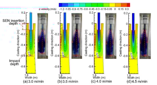
Figure 6.
Comparison of the fluid flow in the mold at various casting speeds obtained via numerical simulation, and hydraulic modeling experiment with a solidified shell and hydrostatic pressure. (a) 3.0 m/min; (b) 3.5 m/min; (c) 4.0 m/min; (d) 4.5 m/min.
On the basis of these definitions, the stream impact depths of the hydraulic modeling experiment with a solidified shell and hydrostatic pressure, the hydraulic modeling experiment without a solidified shell, and the numerical simulation were obtained and are plotted in Figure 7.
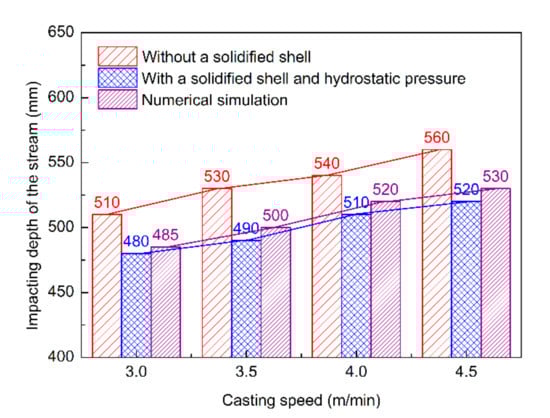
Figure 7.
The impacting depth of the stream in three kinds of methods.
As shown in Figure 7, the obtained impact depths in the mold for the three methods all increase with the casting speed. This is because the boost from the casting speed correspondingly enhances the kinetic energy of the stream that enters the mold from the SEN. Moreover, the impact depth of the stream in the hydraulic modeling experiment with a solidified shell and hydrostatic pressure is 480–520 mm, which is less than the value range of 510–560 mm obtained in the hydraulic modeling experiment without a solidified shell. This difference is mainly owing to the tapered structure of the solidified shell, which increases the wall resistance of the stream as it flows downward, thereby increasing the impact kinetic energy consumption and reducing the impact depth. However, the impact depth value range of 485–530 mm from the numerical simulation with coupled fluid flow and solidification and heat transfer is closer to the results obtained via the hydraulic modeling experiment with a solidified shell and hydrostatic pressure. Therefore, the results from the hydraulic model proposed in this paper can more accurately reflect the flow behavior in a continuous casting mold.
3.2. Level Fluctuation in the Free Surface of the Mold
The meniscus level fluctuation is related to slag entrapment, liquid slag distribution, and slag layer activity. Ultimately, these effects will exert an influence on the quality of the strand. For this reason, the level fluctuation was measured herein using the hydraulic modeling experiment. Figure 8 plots the level fluctuations of eight measurement points (labeled points A–H) in the hydraulic modeling experiment without a solidified shell. Moreover, the standard deviation at the eight measurement points is about ±0.03–± 0.09 mm, and within the allowable error range.
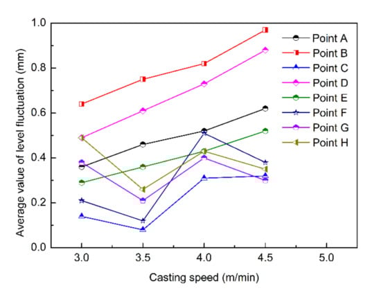
Figure 8.
The average level fluctuation in the free surface at various measurement points.
It can be seen that level fluctuations of points A, C, E, F, G, and H are basically below 0.5 mm at four casting speeds, and they are too small to result in a larger effect on slag entrapment. Nonetheless, level fluctuations of point B and D are about 0.5–1.0 mm, and they are twice as large as others and will also affect the interface behavior between liquid slag and the fluid. Therefore, in order to improve the efficiency of the hydraulic modeling experiment and make it purposeful, this paper selects the two representative measurement points B and D to study and analyzes the level fluctuation in the free surface of the mold.
Figure 9 plots the average level fluctuations and standard deviation at the measurement points B and D in the free surface of the hydraulic modeling experiment with a solidified shell and hydrostatic pressure and without a solidified shell at various casting speeds. The data in Figure 9 show a similar pattern of level fluctuation for the two types of hydraulic modeling experiments, where the average level fluctuation value gradually increases with the casting speed. This behavior is owing to the fact that the kinetic energy of the stream poured into the mold through the SEN increases as the casting speed increases from 3.0 to 4.5 m/min. Correspondingly, the upward backflow energy also increases, thus the disturbance to the free surface of the mold is intensified. However, the level fluctuation of the free surface in the mold with a solidified shell and hydrostatic pressure is more severe than that without a solidified shell. Specifically, at point B (point D), the level fluctuation of the hydraulic modeling experiment with a solidified shell and hydrostatic pressure increases by 3–11% (6–15%) compared with that without a solidified shell. The main reason for this increase is that the tapered structure of the solidified shell causes the downward flow space of the stream to become gradually smaller, whereby the stream is squeezed by the solidified shell. Therefore, the velocity of the upward backflow increases, increasing the disturbance of the liquid surface in the mold. Moreover, the standard deviation at point B without a solidified shell (with a solidified shell and hydrostatic pressure) is about ±0.04–±0.07 mm (±0.05–±0.09 mm), and at point D, it is about ±0.03–±0.06 mm and ±0.04–±0.05 mm, respectively. These standard deviations are within the allowable error range.
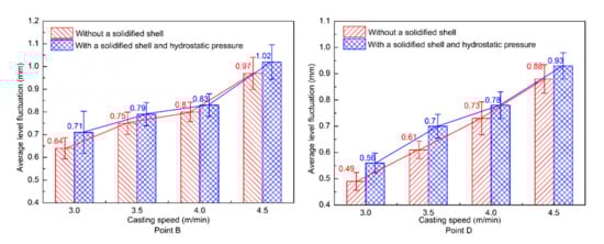
Figure 9.
Level fluctuation in the free surface of the hydraulic modeling experiments with and without a solidified shell and hydrostatic pressure at the measurement point B and point D for various casting speeds.
Compared with the results from the Jin et al. [15], however, the level fluctuation increment obtained herein via the hydraulic modeling experiment with hydrostatic pressure and a solidified shell is not sufficiently large when the section size becomes smaller. There are two main reasons for this discrepancy. On the one hand, the straight SEN used in the hydraulic modeling promotes more downward-flowing fluid, which mitigates the formation of an upward backflow. On the other hand, owing to the effect of the hydrostatic pressure on the solidification flux, the fluid that participates in the upper backflow is reduced and the upward impacting momentum is thus smaller. Therefore, the disturbance of the top surface weakens, and the level fluctuation does not significantly increase.
Further, the level fluctuation at measurement point B in the mold without a solidified shell (with a solidified shell and hydrostatic pressure) is approximately 0.07–0.15 mm larger (0.05–0.15 mm larger) than that at measurement point D. In addition, the level fluctuation difference between the inner and outer arc is because the mold herein is an arc structure that has a small cross-section size. Therefore, the stream is closer to the inner arc when entering the mold, which causes the space around the inner arc to be smaller and the wall resistance to increase. Thus, a backflow around the inner arc is difficult to form and the velocity of the upward backflow reduces. Furthermore, the disturbance of the free surface around the inner arc of the mold reduces. Proximal to the outer arc, there is enough space to form a backflow, and the corresponding upward backflow will be subjected to a smaller wall resistance. As a result, the backflow velocity near the outer arc is also greater and the disturbance of the free surface in the outer arc of the mold increases, which is consistent with the flow field of the mold found herein.
3.3. Dsitribution of Liquid Slag in the Mold
To observe the interface behavior of the liquid slag in the mold, a corresponding hydraulic modeling experiment was carried out using a mixed oil comprising mechanical pump oil and kerosene to model the liquid slag (Figure 10).
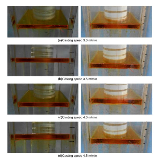
Figure 10.
Distribution of liquid slag in the mold of two sorts of hydraulic modeling experiments at various casting speeds without a solidified shell (left), and with a solidified shell and hydrostatic pressure (right). (a) 3.0 m/min; (b) 3.5 m/min; (c) 4.0 m/min; (d) 4.5 m/min.
The results indicate that the overall distribution uniformity and the covering state of liquid slag layer not only are all favorable in both experiments, but also there is no slag entrapment phenomenon, and the activity of liquid slag in the mold is appropriate under the different casting speeds. In addition, video observation displays that the activity of liquid slag in the mold with a solidified shell and hydrostatic pressure is better than that without a solidified shell. Because of the consideration of a solidified shell, its tapered structure causes the fluid in the mold to be subjected to upward extrusion force, and then the velocity of upward backflow arises, which results in the intensification of free surface disturbance.
4. Conclusions
In this paper, on the basis of the relevant parameters used in Table 1, the flow behavior for a 160 mm × 160 mm cross-section billet continuous casting mold was investigated under a casting speed of 3.0–4.5 m/min via hydraulic modeling experiments considering a solidified shell and hydrostatic pressure, and the results were compared with simulation results. The conclusions obtained are as follows:
(1) Under a casting speed of 3.0–4.5 m/min, the average level fluctuation of the free surface in the mold with a solidified shell and hydrostatic pressure was 3–15% greater than that without a solidified shell. Further, the level fluctuation near the inner arc was 0.05–0.15 mm larger than that around the outer arc.
(2) With the casting speed increasing from 3.0 m/min to 4.5 m/min, the impact depth of the stream increased. Further, the impact depth in the mold with a solidified shell and hydrostatic pressure was 10–30 mm smaller than that without a solidified shell. Moreover, the results of the hydraulic modeling experiment with a solidified shell and hydrostatic pressure were closer to that of numerical simulation than that without a solidified shell. Therefore, the model developed herein can reflect more accurately the actual condition of continuous casting.
(3) The modeled liquid slag in the mold with a solidified shell and hydrostatic pressure was evenly distributed and well covered, with no slag entrapment at the range of casting speed of 3.0–4.5 m/min. In addition, the activity of liquid slag is better with a solidified shell than without one.
Author Contributions
Conceptualization, data curation, writing—original draft, writing—review and editing, P.X. and D.C.; visualization, investigation, formal analysis, writing—original draft, Y.D., H.Y., and P.L.; supervision, M.L., H.D., and J.Y. All authors have read and agreed to the published version of the manuscript.
Funding
This work is supported financially by the Natural Science Foundation of China (NSFC, Project Nos. 51874060, 51874059).
Acknowledgments
The authors thank the members of Laboratory of Metallurgy and Materials, Chongqing University, for the support of this work.
Conflicts of Interest
The authors declare no conflict of interest.
Nomenclature
| Fr | A dimensionless criterion for characterizing the relative magnitude of inertial force and gravity of the fluid |
| Re | A dimensionless criterion for characterizing the relative magnitude of inertial force and viscous force of the fluid |
| D | The thickness of the solidified shell at the cross section (mm) |
| Doutlet | The thickness of the solidified shell at the mold outlet (mm) |
| Z | The distance of the cross section from the mold meniscus (mm) |
| H | The effective height of the mold (mm) |
| Q | The volume flux converted into the solidified shell at the cross section (ml/s) |
| v | The casting speed of the strand (mm/s) |
| Qhole | The volume flux of a single hole with a diameter d (ml/s) |
| μslag, μsteel, μoil and μwater | The dynamic viscosities of liquid slag, molten steel, mixed oil, and water, respectively (kg·m−1·s−1) |
Appendix A
The Derivation Process of Equation (5).
Figure A1 presents how to solve the volume flux Q converted into the solidified shell; it equals the difference value between the volume flux in outer rectangle geometry and the volume flux in inner inverted cone in Figure A1a, and can be divided into several parts to solve. As shown in Figure A1b and Figure A1c, the volume flux of the yellow geometry is and , respectively. However, if the sum of plus is used to represent the difference value of the volume flux, there will be overlap in four corners. The volume flux of the overlap at one corner is in Figure A1d, and the sum of four corners is . Eventually, after subtracting the extra volume flux in four corners, the real volume flux Q converted into the solidified shell is .

Figure A1.
The sketch diagram of solving volume flux converted into the solidified shell: (a) total volume converted into the solidified shell at a cross section; (b) volume components at front and back; (c) volume components at left and right; and (d) surplus volume components at one corner.
The Derivation Process of Equation (6).
The value of Qhole can be obtained experimentally using the measuring device in Figure A2, and the detailed steps are as follows. (a) Selecting a plastic plate (the thickness is ignored) and drilling five small holes of the diameter d on it, as well as then installing it on the bottom of water container and sealing it well. (b) Blocking the small hole and pouring water into the container. When the height of the water level reached Z (mm), opening the small hole and keeping the water level Z constant. (c) Using a 1000 mL beaker to collect the drainage water under the bottom of water container, and recording the time from the start of collection to 1000 mL. (d) Repeating step (c) six times and correspondingly obtaining six times, and then averaging them to get the time t (s). (e) On the basis of the abovementioned results, when the height of the water level is Z, the unit time’s volume flux Qhole of a single small hole of diameter d is . (f) Changing the height Z of water level, and then repeating step (b)~(e). In this paper, the measuring height Z includes 200 mm, 400 mm, 500 mm, 600 mm, 800 mm, and 1000 mm. Thus, we will get six corresponding volume fluxes. (g) Setting the height Z and the volume flux Qhole as the horizontal ordinate and longitudinal ordinate, respectively, and drawing the above six sets of data into the coordinate system. Then, fitting these data to the relationship between Qhole and Z; this paper finds that both are linear, namely, .

Figure A2.
The measuring device of small holes’ volume flux.
References
- Yuan, Q.; Thomas, B.G.; Vanka, S.P. Study of transient flow and particle transport in continuous steel caster molds: Part I. Fluid flow. Metall. Mater. Trans. B 2004, 35, 685–702. [Google Scholar] [CrossRef]
- Li, X.; Li, B.; Liu, Z.; Niu, R.; Liu, Y.; Zhao, C.; Huang, C.; Qiao, H.; Yuan, T. Large Eddy Simulation of Multi-Phase Flow and Slag Entrapment in a Continuous Casting Mold. Metals 2018, 9, 7. [Google Scholar] [CrossRef]
- Lee, J.-E.; Han, H.N.; Oh, K.H.; Yoon, J.-K. A Fully Coupled Analysis of Fluid Flow, Heat Transfer and Stress in Continuous Round Billet Casting. ISIJ Int. 1999, 39, 435–444. [Google Scholar] [CrossRef]
- Zhang, X.; Chen, W.; Scheller, P.R.; Ren, Y.; Zhang, L. Mathematical Modeling of Initial Solidification and Slag Infiltration at the Meniscus of Slab Continuous Casting Mold. JOM 2018, 71, 78–87. [Google Scholar] [CrossRef]
- Thomas, B.G.; Yuan, Q.; Mahmood, S.; Liu, R.; Chaudhary, R. Transport and Entrapment of Particles in Steel Continuous Casting. Met. Mater. Trans. A 2013, 45, 22–35. [Google Scholar] [CrossRef]
- Zhang, X.; Chen, W.; Ren, Y.; Zhang, L. Mathematical Modeling on the Influence of Casting Parameters on Initial Solidification at the Meniscus of Slab Continuous Casting. Metall. Mater. Trans. A 2019, 50, 1444–1460. [Google Scholar] [CrossRef]
- Meng, Y.; Thomas, B.G. Heat-transfer and solidification model of continuous slab casting: CON1D. Metall. Mater. Trans. A 2003, 34, 685–705. [Google Scholar] [CrossRef]
- Long, M.; Chen, H.; Chen, D.; Yu, S.; Liang, B.; Duan, H. A Combined Hybrid 3-D/2-D Model for Flow and Solidification Prediction during Slab Continuous Casting. Metals 2018, 8, 182. [Google Scholar]
- Srinivas, P.S.; Mishra, D.K.; Gupta, R.; Korath, J.M.; Jana, A.K. Vortex characteristics due to nozzle clogging in water caster mould: Modelling and validation. Can. Metall. Q. 2018, 58, 308–324. [Google Scholar] [CrossRef]
- Szekely, J.; Yadoya, R.T. The physical and mathematical modeling of the flow field in the mold region in continuous casting systems: Part I. Model studies with aqueous systems. Metall. Mater. Trans. A 1972, 3, 2673–2680. [Google Scholar] [CrossRef]
- Gupta, D.; Lahiri, A.K. Water-Modeling Study of the Surface Disturbances in Continuous Slab Caster. Metall. Mater. Trans. A 1994, 25, 227–233. [Google Scholar] [CrossRef]
- Gupta, D.; Lahiri, A.K. A water model study of the flow asymmetry inside a continuous slab casting mold. Metall. Mater. Trans. A 1996, 27, 757–764. [Google Scholar] [CrossRef]
- Gupta, D.; Chakraborty, S.; Lahiri, A.K. Asymmetry and Oscillation of the Fluid Flow Pattern in a Continuous Casting Mould: A Water Model Study. ISIJ Int. 1997, 37, 654–658. [Google Scholar] [CrossRef]
- Jeon, Y.J.; Sung, H.J.; Lee, S. Flow Oscillations and Meniscus Fluctuations in a Funnel-Type Water Mold Model. Metall. Mater. Trans. A 2009, 41, 121–130. [Google Scholar] [CrossRef]
- Jin, X.; Chen, D.F.; Zhang, D.J.; Xie, X.; Bi, Y.Y. Water model study on fluid flow in slab continuous casting mould with solidified shell. Ironmak. Steelmak. 2011, 38, 155–159. [Google Scholar] [CrossRef]
- Zhang, K.; Liu, J.; Cui, H.; Xiao, C. Analysis of Meniscus Fluctuation in a Continuous Casting Slab Mold. Metall. Mater. Trans. A 2018, 49, 1174–1184. [Google Scholar] [CrossRef]
- Szekely, J.; Yadoya, R.T. The physical and mathematical modeling of fluid field in the mold region in continuous casting systems: Part II. The mathematical representation of the turbulent flow field. Metall. Trans. 1973, 4, 1379–1388. [Google Scholar] [CrossRef]
- Lan, X.K.; Khodadadi, J.M.; Shen, F. Evaluation of six k-ε turbulence model predictions of flow in a continuous casting billet-mold water model using laser doppler velocimetry measurements. Metall. Mater. Trans. A 1997, 28, 321–332. [Google Scholar] [CrossRef]
- Ramos-Banderas, A.; Sánchez-Pérez, R.; Demedices-García, L.; Palafox-Ramos, J.; Díaz-Cruz, M.; Morales, R.D. Mathematical simulation and physical modeling of unsteady fluid flows in a water model of a slab mold. Metall. Mater. Trans. B 2004, 35, 449–460. [Google Scholar] [CrossRef]
- Miranda, R.; Barron, M.A.; Barreto, J.; Hoyos, L.; Gonzalez, J. Experimental and Numerical Analysis of the Free Surface in a Water Model of a Slab Continuous Casting Mold. ISIJ Int. 2005, 45, 1626–1635. [Google Scholar] [CrossRef]
- Liu, Z.; Li, B.; Vakhrushev, A.; Wu, M.; Ludwig, A. Physical and Numerical Modeling of Exposed Slag Eye in Continuous Casting Mold using Euler–Euler Approach. Steel Res. Int. 2018, 90, 1800117. [Google Scholar] [CrossRef]
- Huang, J.; Yuan, Z.; Shi, S.; Wang, B.; Liu, C. Flow Characteristics for Two-Strand Tundish in Continuous Slab Casting Using PIV. Metals 2019, 9, 239. [Google Scholar] [CrossRef]
- Zhang, L.W.; Wang, Z.L.; Xu, C.J.; Li, S.L.; Ai, X.G.; Li, J. A vertical continuous casting machine for large blooms. Ironmak. Steelmak. 2017, 46, 742–746. [Google Scholar] [CrossRef]
- Chen, H.; Long, M.; Chen, D.; Liu, T.; Duan, H. Numerical study on the characteristics of solute distribution and the formation of centerline segregation in continuous casting (CC) slab. Int. J. Heat Mass Transf. 2018, 126, 843–853. [Google Scholar] [CrossRef]
© 2020 by the authors. Licensee MDPI, Basel, Switzerland. This article is an open access article distributed under the terms and conditions of the Creative Commons Attribution (CC BY) license (http://creativecommons.org/licenses/by/4.0/).