Abstract
Additive manufacturing (AM) has recently been receiving global attention. As an innovative alternative to existing manufacturing technologies, AM can produce three-dimensional objects from various materials. In the manufacturing industry, AM improves production cost, time, and quality in comparison to existing methods. In addition, AM is applied in the fabrication and production of objects in diverse fields. In particular, metal AM has been continuously commercialized in high value-added industries such as aerospace and health care by many research and development projects. However, the applicability of metal AM to the mold and die industry and other low value-added industries is limited because AM is not as economical as current manufacturing technologies. Therefore, this paper proposes an effective solution to the problem. This study examines a method for using direct energy deposition and heterogeneous materials, a heterogeneous material additive-manufacturing process for metals used to optimize the cooling channels and a key process in manufacturing hot-stamping dies. The improvements in the cooling performances and uniform cooling were evaluated by heat-flow analysis in a continuous process. Finally, trial products were fabricated using the proposed method, and a trial for hot stamping was conducted to examine the possibility of it being used in commercial applications.
1. Introduction
In recent years, additive manufacturing (AM) has been attracting more attention globally. AM technology can make physically tangible models from virtual three-dimensional (3D) data. In particular, metal AM is applied in high value-added industries such as aerospace, health care, power generation, and automobiles. Therefore, technical research and development projects for commercialization are continuously conducted in diverse ways [1,2]. ASTM F2792-12a standardizes the term rapid prototyping (RP) in 3D printing or AM [3,4].
Depending on the deposition type, AM is classified into the following seven categories: material extrusion (ME); material jetting (MJ); binder jetting (BJ); sheet lamination (SL); vat photo-polymerization (VP); powder bed fusion (PBF); and direct energy deposition (DED) [1,4]. Among these methods, PBF and DED are metal AM technologies. In practice, ME, MJ, BJ, and SL can also be used for metal AM; however, they are rarely adopted. Since metal AM requires expensive materials and its manufacturing process is time-consuming, it is actively studied and applied in high value-added industries [5,6,7,8].
Ahn and Lee et al. studied the sustainable application of metal AM in fabrication processes and eco-friendly manufacturing fields [9,10,11,12]. To enhance the cooling performance of injection molds, Kim et al. used a hybrid tooling technology combining machining and AM processes to fabricate an injection mold with the same 3D cooling channel as the product shape. The authors applied the technology to the injection molding of switch covers for cars [13]. Park et al. [14,15] examined the microstructures and heat treatment of tool steels deposited by the DED process and microstructural changes of the materials and energy input characteristics during the AM process. They also proposed a method for improving the surface hardness of those materials. Hong et al. [16] investigated trimming die manufacturing technologies using heterogeneous materials for AM and introduced commercial applications.
The most pressing challenge for the 21st-century automobile industry is developing a technology to improve fuel efficiency through weight reduction. As for car body parts, research and development projects have been continuously conducted to develop materials and processes, which could protect passengers during an accident and reduce the car weight. Hot stamping is a core technology most commonly used for commercial applications. Since boron steel can improve its hardenability by rapid cooling after heating, hot stamping heats the boron steel to a minimum of 900 °C. Once boron steel attains a complete austenitic state, it is transferred into a die and rapidly cooled at the critical cooling rate of at least 30 °C/S. Thus, a homogeneous martensitic structure is obtained. Because forming and cooling processes are performed simultaneously inside a die, rapid and uniform cooling due to optimal cooling-channel design forms a core technology. Gun-drill-based linear-machining is a conventional technique to fabricate cooling channels of a hot-stamping die with free-form surfaces. However, when employing this method, it is impossible to maintain a consistent distance between conformal cooling-channel centers and the product surface. This results in reduced formed-product strength owing to reduced cooling performance and non-uniform cooling during the forming process. This, in turn, leads to persistent problems related to inconsistent product-dimension accuracy caused by spring-back occurrences. Several studies have been performed to optimize hot stamping-die cooling channels to solve these problems.
Mori et al. [17] proposed an optimization technology for producing hot-stamping parts. Abdulhay et al. experimentally examined the cooling and forming characteristics of hot stamping and proposed an alternative method of hot stamping to computer-aided engineering (CAE) [18]. Hu et al. examined variations in the cooling performance according to the cooling channel design of the hot-stamping die to discuss the correlation between the cooling performance and mass flux or cooling channel shape [19]. Lim et al. [20] investigated designing the cooling channel of a hot-stamping tool, which could enable uniform high-strength components to be manufactured in a hot-stamping process and introduced a uniform cooling technique that required a die to be divided.
Studies have reported methods to optimize cooling-channel designs to ensure improved cooling performance along with uniform cooling of hot-stamping dies by dividing individual cooling blocks. However, it is not possible to manufacture hot-stamping dies with conformal cooling channels that match their curved shape owing to linear-machining limitations.
The proposed study investigates a technology to fabricate hot-stamping dies with identical product-shaped conformal cooling channels via coupons and heterogeneous material additive-manufacturing (HMAM) technology to overcome the limitations of the linear machining process. The HMAM technique improves production expenses and processes by sorting different parts of a target product or die into functional and non-functional units requiring superior and relatively modest mechanical properties, respectively. AM technology is exclusively applicable to functional groups [16].
Studies concerning the production of conformal cooling channels propose using PBF and DED techniques for injection molds with small AM surface area (100 mm × 100 mm × 5 mm (length × width × height) or less). However, very few AM-process-based studies investigate the production of conformal cooling channels in hot-stamping dies of high-strength materials with large surface areas (300 mm × 190 mm × 5 mm (width × length × height) or larger). This is because of limitations associated with equipment availability and lacking powder-material development.
This study was organized as follows. First, the heat-treatment and mechanical properties of commercial hot die materials were analyzed. Second, among the commercial hot die materials, one material with excellent thermal conductivity was obtained in the form of metal powder. After developing an optimal layered manufacturing process and a heat-treatment process, the mechanical properties were evaluated. Third, after designing a hot-stamping die with the same conformal cooling channel as the product shape, the cooling and uniform cooling performances were evaluated via continuous process thermal flow analysis. Fourth, to solve the crack problem that occurs when AM process in the large-area high-hardness materials are performed, the difference in residual stress according to the base material heating process using a real-time base material heating device was examined. In addition, considering the residual stress according to the base material heating temperature, a prototype hot-stamping die was fabricated, and then, the cooling performances of the developed technology and quality of the die product were evaluated.
2. Materials and Methods
2.1. Examination of Commercial Hot Work Tool Steel and the Selection of Materials
Unlike cold work tool steel that can serve as a forming load at room temperature (approximately 10–30 °C), hot die steel for a hot-stamping die is required to withstand high temperatures in the range of 150–200 °C. Moreover, abrasion resistance at high temperatures, high thermal conductivity for rapid cooling, and thermal fatigue resistance to withstand repeated heating and cooling are considered essential properties. Figure 1 shows a commercial hot-stamping die, which includes a casting fastened to a press for forming an object, base plate with a cooling water pipeline, and cooling block, which is the main functional unit for cooling and forming when manufacturing hot-stamping parts. This study optimized the cooling channel by applying 3D AM to the cooling block. This study also improved the cooling performance by locally applying hot die steel with high thermal conductivity to the surface and using the heterogeneous material AM technology to use the materials efficiently. HTCS-150 developed by ROVALMA co. is applied to the cooling block, which is the functional unit for forming, while low-cost FC300 and S45C materials used for the body part and base plate, respectively, are the non-functional units.
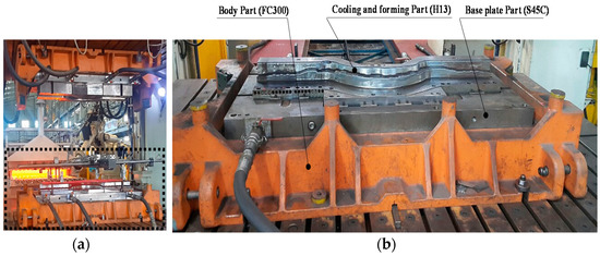
Figure 1.
Example of a commercial hot-stamping die (a) production of hot-stamping parts (b) material applications of a hot-stamping die by function.
Recently, new materials with high thermal conductivity and abrasion resistance have been developed by improving H13 steel. Since the new materials are two to six times more expensive than the existing materials, their applicability to commercial hot-stamping dies is limited. Moreover, additional technical development is required to solve the problem of non-uniformity of cooling during hot stamping.
Table 1 and Table 2 analyze the main alloy elements and mechanical properties of new materials. As thermal conductivity and hardness are the most important mechanical properties of hot die steel, HTCS-150 was applied to the functional unit of the hot-stamping die. Compared with H13, which is commonly used as hot die steel, HTCS-150 reduces the amount of Cr, increases the content of Mo, and adds Cu and W. Under similar hardness conditions after heat treatment, the thermal conductivity of HTCS-150 was improved by at least 40% in comparison to H13. Consequently, HTCS-150 is a hot die steel material that can improve the cooling performance of the functional part of the hot-stamping die.

Table 1.
Chemical composition of hot work tool steels (wt.%).
Table 2.
Mechanical properties after heat treatment of commercial hot work tool steels.
2.2. Optimization of the Additive Manufacturing (AM) Process for HTCS-150 and Heat Treatment
Of the available DED equipment, the laser-aided direct metal tooling AM equipment (MX_3; Insstek Co.; Daejeon, South Korea) was used in this study. MX_3 can manufacture metal products identical to 3D-CAD models using a 2-kW optic-fiber laser to melt the base metal. This is followed by adding the spherical metal powder to the melt pool to facilitate continuous melting and deposition. Unlike the soft-tooling SLM (selective laser-melting) equipment (Concept Laser Co., Lichtenfels, Germany), MX_3 is considered a hard-tooling device. MX_3 exploits the complete-melting adhesion method during metal-powder deposition, thereby creating final products with mechanical properties identical or superior to those of the bulk material. The characteristics of the soft-and hard-tooling equipment are listed in Table 3. While most existing AM equipment offers limited options in terms of usable metal powders, MX_3 equipment used in this study is compatible with most commercial metal powders. This makes them suitable for the development and commercialization of new powders. The HTCS-150 bulk specimen, which was selected for the functional units (cooling channel coupon and surface) of the hot-stamping die, consists of approximately average 100 µm size spherical particles (supplied by ROVALMA Co.; Barcelona, Spain). The gas atomizing method was used to convert it into metal powder for the DED process (Figure 2).
Table 3.
Characteristics of soft- and hard-tooling metal additive manufacturing (AM) equipment.
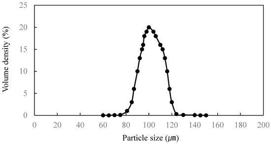
Figure 2.
HTCS-150 powder particle size for the laser deposition.
The AM process was then optimized, as summarized in Table 4. The microstructure of the HTCS-150 bulk specimen and the specimens fabricated by the DED process were analyzed using field-emission scanning electron microscopy (FE-SEM). The microstructures are shown in Figure 3. In the analysis, the HTCS-150 microstructure bulk displayed carbide precipitation between the pearlite and ferrite matrices. The specimen manufactured by the AM process had a martensite structure that was more uniform than the HTCS-150 bulk specimen. Such uniformity is attributed to the rapid cooling of AM; no defects, such as pores and blowholes, were observed.
Table 4.
DED process conditions for trial products of HTCS-150.
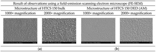
Figure 3.
Analysis results of the microstructures of the HTCS-150 bulk and the specimen made by the AM process (a) microstructure of the HTCS-150 bulk material (b) microstructure of the HTCS-150 AM material.
The HTCS-150 specimen fabricated by the AM process and the existing HTCS-150 bulk were evaluated in terms of thermal conductivity according to the temperature without heat treatment by conducting a laser flash analysis (LFA). As summarized in Table 5, the Vickers-hardness tester was used to measure the values of the internal and surface hardness at room temperature. The HTCS-150 specimen fabricated by the AM process without heat treatment exhibited a thermal conductivity of approximately 30 W/m-K. This is higher than commercial hot die steel (H13); however, the thermal conductivity was 75% of the thermally treated HTCS-150 bulk. Accordingly, an additional heat-treatment process was conducted to improve thermal conductivity.
Table 5.
Thermal conductivity and surface hardness of HTCS-150 without heat treatment.
The applied heat-treatment process is shown in Figure 4. In contrast to the existing H13 material undergoing three heat-treatment processes of annealing, quenching and tempering, the heat-treatment process of HTCS-150 material consists of three process of austenization, quenching and tempering. Figure 5 is the result of calculating the equilibrium phase fraction according to the temperature of the HTCS-150 using the JMatPro software Version 7.0 (Sentesoftware.co, Guildford, Surrey, GU2 7YG, UK) base on the composition shown in Table 1. According to the carbon content, it can be seen that austenite is formed, and carbide is crystallized from the liquid phase during solidification. However, it is predicted that during actual solidification, the liquid phase section is extended due to the non-equilibrium reaction, and a large amount of crystallized carbide is generated. Figure 6 shows the microstructure of the HTCS-150 bulk specimen applied with the heat-treatment process and the specimen manufactured by the AM process. As a result of EDS (energy-dispersive X-ray spectroscopy) component analysis, it was analyzed that Mo-W based intermetallic compounds exist in the matrix tissue. In contrast to bulk materials, it was found that the intermetallic compounds were finely distributed in the case of the specimen manufactured by AM process. This is judged to be a result of different specimen manufacturing method. In addition, it is predicted that the specimens manufactured by the AM process will exhibit better toughness than bulk materials because the intermetallic compounds exist finer than the bulk materials after the heat-treatment process is applied. Table 6 reported the thermal conductivity and hardness values of the bulk specimen to which the heat-treatment process was applied, and the specimen manufactured by AM process. As a result of applying the heat-treatment process, the thermal conductivity of the bulk specimen decreased from 50.65 W/m-K to 40.27 W/m-K based on 27 °C and the hardness value improved from Hv 85 to Hv 530. On the other hand, in the case of the specimen manufactured with AM, the thermal conductivity improved from 30.00 w/m-K to 42.20 W/m-K, and the hardness value decreased slightly from 550 Hv to 490 Hv. However, as shown in Table 2, considering that the hardness values of commercial hot mold steel materials are Hv 480 to Hv 550, the HTCS-150 material manufactured by the AM process is within the range of hardness that can be used when making a hot-stamping die. In addition, compared to the existing hot mold steel H13 material, the hardness decreased by 7.2% while the thermal conductivity was improved by 41%.
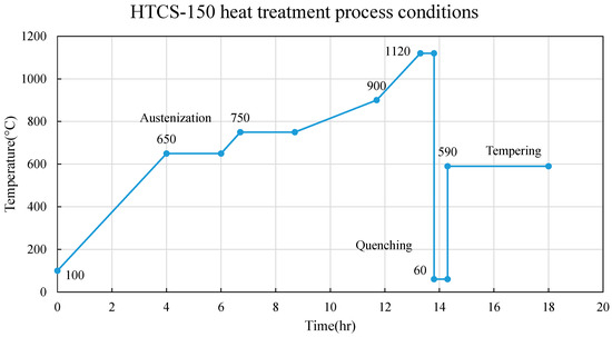
Figure 4.
The heat-treatment process conditions of HTCS-150 steel.
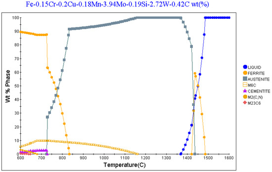
Figure 5.
Equilibrium phase fraction by JMatPro software of HTCS-150 steel.
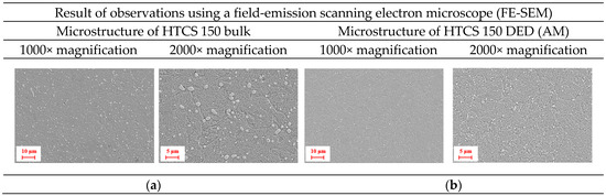
Figure 6.
Analysis results of the microstructures of the HTCS-150 material applied with heat-treatment process (a) microstructure of the HTCS-150 bulk material (b) microstructure of the HTCS-150 AM material.
Table 6.
Thermal conductivity and surface hardness of HTCS-150 with heat treatment.
3. Die Design and the Heat-Flow Analysis of the Continuous Process
3.1. Die Design
Compared with the conventional linear cooling channel system for the hot-stamping die, the cooling performance of the conformal cooling channel system, to which the new AM technology is applied, was quantitatively evaluated. To this end, the reinforcing center pillar part, which exhibits non-uniform cooling and hot spots during the manufacturing process due to a drastic variation in the length of the product section, was scaled to ½ and symmetrically designed. The conformal cooling channel system using AM technology was then applied to the LH side, while the existing linear cooling channel system was applied to the RH side. A conformal cooling channel, as the name implies, refers to channels that conform to the surface of the mold cavity. Figure 7 illustrates the die that was designed.
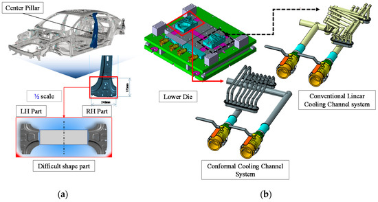
Figure 7.
Center pillar shape and die concept for trial forming and evaluation; (a) a center pillar part (b) die and cooling channel design concept.
As shown in Figure 7b, when the cooling channel is manufactured using a conventional gun-drill-based linear processing technique, the product shape becomes uneven. In addition, it is impossible to manufacture conformal cooling channels of curved products located at the same distance from the die surface and channels. However, these problems can be solved using coupons and HMAM technology as shown in Figure 8a,b.
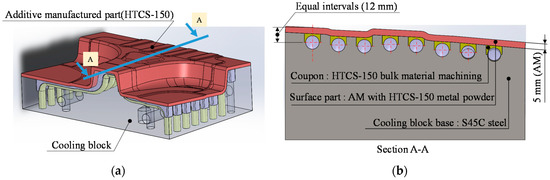
Figure 8.
Fabrication concept for the conformal cooling channel using AM technology (a) cooling block iso-view (b) cooling block Section A-A.
Figure 8 shows the design and fabrication concept of a hot-stamping cooling block incorporating a conformal cooling channel manufactured using HMAM technology. The hot-stamping part is divided into three parts. For the non-functional unit, S45C was used. Since it is difficult to make a prototype with the DED in the functional part, the coupon of the semicircle was fabricated by machining and assembled on the channel of the non-functional unit. It was then deposited on the die surface by the DED technique. To improve the durability of the die, a 7 mm-thick HTCS-150 metal powder (Rovalma Co.; Barcelona, Spain) composed of spherical particles having an average surface area of 100 μm was used.
The initial surface roughness (Ra) of the AM-fabricated cooling block was approximately 100–200 µm. The surface quality of the finished block was improved by machining its surface post completion of the AM process, thereby meeting the Ra-value requirement of 0.4–1.6 µm. Additionally, the roughness of the cooling channel’s inner surface was improved over that of integrated conformal cooling channels fabricated via injection molding using conventional AM equipment. The bottom and top coupon parts constituting the cooling channels were machined to achieve Ra values in the 0.4–1.6 µm range prior to being assembled and attached to the block via HMAM. The die design was optimized in two criteria: The first is to minimize the cooling time during forming and ensure the durability of the cooling block, and the second is to achieve uniform cooling (i.e., the temperature must be kept constant at all point on the die surface).
3.2. Heat-Flow Analysis of Continuous Process
To evaluate the cooling performance and uniformity of the existing linear cooling channel and proposed conformal cooling channel, a finite volume method (FVM)-based SOLIDWORKS Flow Simulation 2015 using the Navier–Stokes equation was applied. (Dassault systemes.co, Velizy-Villavoublay, France) This equation describes the motion of the viscous fluid, which was implemented for the cooling analysis and heat flow of the continuous process. Table 7 summarizes the main conditions of the heat flow analysis in the continuous process. Figure 9 depicts the analysis result comparing inlet and outlet cooling-water flow velocities observed when using cooling blocks incorporating the conventional linear and proposed conformal cooling channels. As can be observed, the velocities decrease as cooling water flows away from its supply point at the inlet, which could be the effect of the pressure drop away from the inlet. The block comprising linear cooling channels was asymmetric in shape, making it difficult to compare cooling-water flow velocities within its channels against those within conformal cooling channels of the proposed block (refer Figure 7b).
Table 7.
Heat-flow analysis conditions.
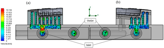
Figure 9.
Analysis of cooling-water flow velocity in die due to change in cooling-channel system through continuous thermal-flow analysis in (a) conformal cooling channel proposed in this study; (b) conventional linear cooling channel.
Figure 10 shows the cooling water temperature analysis results at the outlet pipe after cooling through a continuous process heat flow. The analysis results demonstrated that the coolant temperature at the outlet of the die with the conventional linear cooling channel was 32.50 °C. The coolant temperature at the outlet of the die with the developed conformal cooling channel was 33.83 °C. For the conformal cooling channel, the cooling performance can be improved by increasing the flow velocity of the fluid and applying the high thermal conductivity die steel.
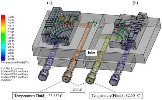
Figure 10.
Temperature analysis of coolant-outlet pipe using continuous process heat flow in (a) conformal cooling channel; (b) conventional linear cooling channel.
Figure 11 shows the temperature distribution analysis of the cooling channel surface of each lower die in the cooling block through the continuous process heat flow. Table 8 summarizes the maximum temperature of the cooling channel surface of each die. The analysis results demonstrate that the maximum temperature of the surface part of the conventional linear cooling channel was 481.5 °C and the developed conformal cooling channel was 213.5 °C. Compared to conventional technology, the surface temperature of the conformal cooling channel was 268 °C lower. In addition, for a die with a conventional linear cooling channel, a hot spot is issued locally. However, for a die having a conformal cooling channel, a hot spot is not generated, and the temperature of the cooling channel surface is relatively uniform compared to conventional technology.
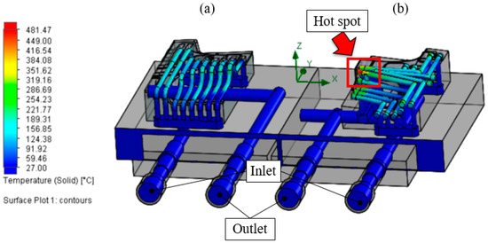
Figure 11.
Temperature distribution of cooling water obtained through heat-flow analysis of continuous process; surface temperature distribution of (a) conformal cooling channel; (b) conventional linear cooling channel.
Table 8.
Comparison of the maximum temperature of the cooling channel surface of each die.
Figure 12 shows the temperature distribution of the die with the conventional linear cooling channels and with the developed conformal cooling channels. Table 9 lists the maximum, minimum, and average temperatures of each die. The thermal flow analysis demonstrated that the die with the conformal cooling channel exhibited an average temperature that was at least 40% lower than the conventional linear cooling channel die. This is because the high heat-conductive die steel is applied to the surface of the die, and conformal cooling channels are applied to increase the flow velocity of the cooling water. As a result, the cooling performance improved at the contact surface during the hot-stamping process.
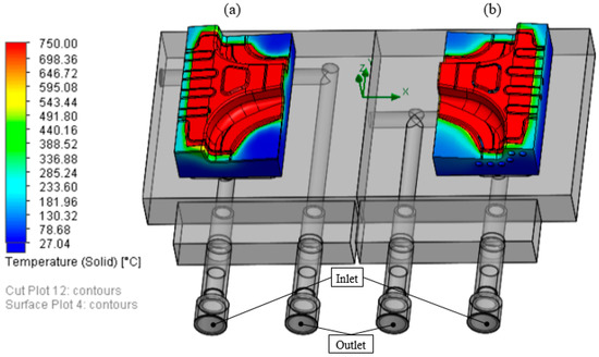
Figure 12.
Comparison of the average temperature of each die in the continuous process heat flow (a) die applied to conformal cooling channel of this study (b) die applied with conventional linear cooling channel.
Table 9.
Temperature comparison of each die as a result of the continuous process heat flow.
4. Die Fabrication and Trial Hot-Stamping Evaluation
4.1. Fabrication of Hot-Stamping Die with Conformal Cooling Channel
Figure 13 illustrates the overall process of fabricating a hot-stamping die for evaluating trial hot stamping. The hot-stamping die was fabricated in the following order. After the cooling block body and coupon were made, AM was conducted. This was followed by machining, heat treatment, and assembly. As described in the preceding sections, the AM-fabricated cooling block surface was machined and inspected for the development of cracks using the liquid-penetrant testing method. The cooling block was then combined with the hot-stamping die body, and the die was finally fabricated. Figure 14 depicts the proposed cooling block assembly during the different manufacturing phases—(a) surface AM processing after cooling block and coupon assembly; (b) post-AM processing; (c) post-AM processing and machining to enhance surface quality.
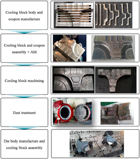
Figure 13.
The overall process of fabricating a hot-stamping die with a conformal cooling channel.
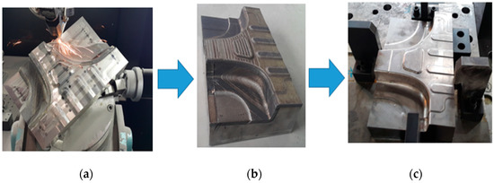
Figure 14.
Fabrication of a cooling block with a conformal cooling channel using heterogeneous material AM technology: (a) cooling block body coupon assembly, (b) cooling block after AM processing (c) cooling block after machining the AM cooling block surface.
Figure 15 depicts the results of liquid-penetrant testing performed for crack detection upon completion of the AM and surface-machining processes. As can be observed, the inspection revealed the presence of cracks caused by increased residual stress at certain points. To address this concern, the authors investigated a procedure based on a real-time base-metal heating technique to reduce residual stresses in the finished assembly. Figure 16 depicts schematics of sample preparation and points of residual stress measurement to study changes in residual stress upon applying a real-time base-metal heating technique during the AM process. Sample preparation was performed at base-metal temperatures of 25, 150, and 250 °C. The experiment was performed without using a vacuum chamber to heat the base metal. Instead, the base metal was placed on a resistance-heating table in an open atmosphere to attain a certain temperature through conduction. Residual stress values were measured using an X-ray diffractometry (XRD)-based residual stress measuring instrument. The instrument is based on Bragg’s law, which establishes the relationship between atomic spacing and angle of incidence at which the X-rays enter a metal crystal as the underlying principle. Table 10 lists residual stress values in the base-metal state and changes therein at each temperature prior to and post sample preparation, respectively.
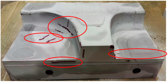
Figure 15.
Cracks observed in the liquid penetration test after additive manufacturing and surface machining.
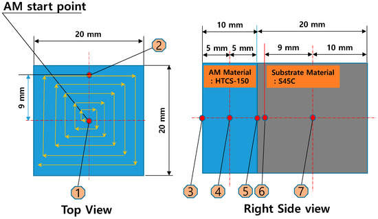
Figure 16.
Schematic of AM process and measurement positions of residual stress.
Table 10.
Residual stress with different heating conditions.
Experimental results reveal that compared to the highest residual stress observed during the AM process at 25 °C base metal, heating the base metal to 150 and 250 °C reduces residual stress values by 46% and 77%, respectively. Additionally, when performing AM in 25 °C base metal, the highest residual stress occurs at Position 5 located at the boundary between the base and AM metals, whereas the same occurred at Position 4 at the middle of the additive metal in base metal of 150 °C and 250 °C. Considering that cracks tend to occur at the interface between the substrate and AM metal, application of the real-time heating technique reduces residual stresses and changes the location of the maximum residual stress. Based on the findings, the cooling block was repaired for observed cracks and finished to satisfaction. Figure 17 shows the upper and lower parts of the complete hot-stamping die.
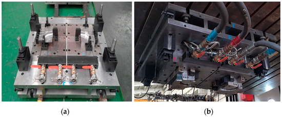
Figure 17.
Assembled cooling block body (a) lower punch cooling block combined with the die body (b) upper pad cooling block combined with the die body.
4.2. Trial Hot-Stamping Evaluation
Trial hot stamping was conducted using the hot-stamping die, which was fabricated by the proposed technology. Table 11 summarizes the main conditions for trial hot stamping. Figure 18 presents the qualitative evaluation results that were acquired by measuring the temperature of the material and the die by a thermal camera during trial hot stamping. The heat furnace was opened and closed. The following temperatures were compared: the temperature of the material; the temperature of the material deposited on the die; the temperature immediately after the rise of the die; and the temperature 5 s after the rise of the die. Compared with the existing technology, the conformal cooling channel improved the cooling performance and enabled uniform cooling.
Table 11.
Main stamping process conditions.
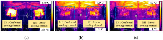
Figure 18.
Results of measurement by thermal imaging camera before and after forming: (a) heated blank placed on die, (b) the temperature comparison immediately after the rise of the die, and (c) the temperature comparison 5 s after the rise of the die.
Figure 19 depicts points at which temperature measurements were performed until the cooling-block surface attained ambient temperature after completion of the forming and cooling stages. Table 12 lists changes in the die-product temperature during the hot-stamping processes involving conformal as well as linear cooling channels. The said temperature measurements were performed using a thermal-imaging camera or contact thermometer. As observed, based on the 15 s required for the forming and cooling process, the cooling rates of the conventional and developed technologies were evaluated and found to be 43.20 °C/s, and 44.13 °C/s, respectively, thereby confirming the improved cooling performance of the proposed configuration.
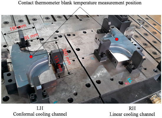
Figure 19.
Product temperature measurement positions on the die-cooling block surface after forming and cooling.
Table 12.
Temperature results measured during stamping process.
Additionally, the surface temperature of the conformal cooling-channel die equaled the ambient temperature of approximately 10 °C. This observation was made 70 s after modeling completion. In contrast, the conventional linear-cooling-channel die never attained the ambient temperature. Additionally, tensile strengths of the product′s horizontal and vertical planes, expected to remain vulnerable to cooling during the forming process, were verified. To this end, samples were collected locally and measured for hardness using the Vickers hardness method; subsequently, the hardness values obtained were converted to tensile strength, as depicted in Figure 20. Results reveal that observed Vickers hardness values on horizontal and vertical planes of the finished product exceeded 480 Hv or 1500 MPa (equivalent tensile strength). The tensile strength is converted from hardness value by referring ASTM A370. This confirms the commercialization potential of the proposed technique. The conformal cooling-channel die demonstrated reduced variation in hardness across the horizontal plane compared to its linear cooling-channel counterpart. This is attributable to the effect of uniform cooling.
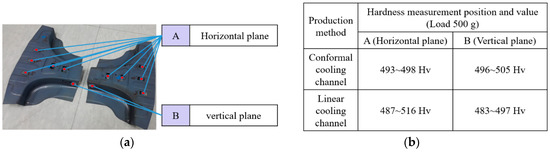
Figure 20.
Vickers hardness measurements of the hot stamped product: (a) measurement positions (horizontal and vertical plane), (b) Vickers hardness measurements.
5. Conclusions
This study aimed to efficiently use materials for a hot-stamping die and improve its cooling performance and manufacturing process. To this end, this study used heterogeneous material AM technology to fabricate a hot-stamping die and examine the various mechanical properties. After evaluating the cooling performance of the developed technology under mass production conditions, the following conclusions were drawn.
- (1)
- In comparison with H13, which is applied to the functional unit of the cooling block during the manufacturing process of the hot-stamping die, DAC-P, W360, and HTCS-150 have improved thermal conductivities. This study examined not only the main alloy components of these materials but also their mechanical properties. This includes their hardness, thermal conductivity, and density after heat treatment. HTCS-150, which was selected as the material of the trial die, exhibited a 40% higher thermal conductivity than a conventional hot-die steel (H13) after AM and heat treatment. Accordingly, HTCS-150 can contribute to improving cooling efficiency.
- (2)
- The proposed design concept of the cooling block with the conformal cooling channel was used for the heat flow analysis of a continuous process. In the analysis, the possibility of improving cooling efficiency and achieving uniform cooling was examined. The mean temperature of the die for the continuous hot-stamping process was lowered by at least 40% compared to current technology. Moreover, the uniformity of the cooling could be more effectively ensured by the developed technology.
- (3)
- A technology for fabricating a cooling block for the hot-stamping die, which includes the conformal cooling channel with the same shape, was developed. Hemispherical cooling channels were machined on S45C base material of low-cost. A hemispherical coupon was fabricated and joined to the block. Finally, metal powder with high thermal conductivity was deposited on the cooling block surface via the heterogeneous material AM technology. Thus, the proposed technology could efficiently address non-uniform cooling caused by the existing linear cooling channel. Moreover, the cooling efficiency can be improved, and the cooling channel design can be simplified.
- (4)
- Prototype die was manufactured using the developed technology, and it was confirmed that cracks occurred in some sections when AM was applied to the surface. This is thought to be caused by the increase in residual stress during large-area AM processing of high-hardness materials.
- (5)
- To solve this problem, the residual stress change amount by applying the real-time base material heating technology during the lamination process was evaluated. It is confirmed that the residual stress amount was reduced by adapting the real-time base material heating device.
- (6)
- Results of thermal camera-based temperature measurements performed after completion of the fabrication process reveal the proposed technique to demonstrate more uniform cooling effects compared to its conventional counterpart. Additionally, contact thermometer-based temperature measurements were performed near the center of each cooling block immediately upon completion of the forming process. The cooling rates of the die with the conventional and proposed cooling channels were 43.20 °C/s, and 44.13 °C/s, respectively. This confirms the improved cooling performance of the configuration proposed in this study.
- (7)
- As a result of evaluating the fabrication costs for one cooling block, it was found that the proposed technology costs 4185 USD to fabricate one cooling block, while the existing technology costs 2410 USD. Although the cost is increased by 1.7 times, commercialization of the proposed technology of this study is deemed feasible considering that the proposed method enhances cooling performance and the mold cost portion in fabricating hot-stamping parts. In addition, we believe that it is feasible to further reduce the fabrication cost of the developed technology through follow-up studies.
As future research, the authors intend to investigate the crack generation and prediction technology using computer-aided engineering to reduce residual stress that occurs during the lamination of high-hardness metal products of various shapes and sizes.
6. Patent
“METHOD OF MANUFACTURING COOLING BLOCK FOR HOT STAMPING MOLD USING THREE-DIMENSIONAL METAL PRINTER” Patent registration number Korea: 10-1647890, USA: 9.849.548, China: ZL 201580000608.7.
Author Contributions
Conceptualization, M.-P.H. and Y.-S.K.; investigation, J.-J.K., W.-S.K., M.-K.L. and K.-M.B.; data curation, M.-P.H., J.-J.K., W.-S.K. and M.-K.L.; writing—original draft preparation, M.-P.H.; writing—review and editing, Y.-S.K. and J.-H.S.; supervision, J.-H.S. All authors have read and agreed to the published version of the manuscript.
Funding
This study has been conducted with the support of the Korea Institute of Industrial Technology as “Development of intelligent root technology with add-on modules (kitech Eo-20-0017) and the Ministry of Trade, Industry and Energy the Global Professional Technology Development Project (20000231).
Acknowledgments
The authors would like to thank those associated with the co-research organizations (Ilji Tech Co., Ltd. and Shinyoung Co., Ltd. in South Korea and with Rovalma S.A. in Spain).
Conflicts of Interest
The authors declare no conflict of interest.
References
- Milewski, J.O. Additive Manufacturing of Metals; Springer: Cham, Switzerland, 2017. [Google Scholar]
- Li, Y.; Hsu, K.; Baughman, B.; Godfrey, D.; Medina, F.; Menon, M.; Weiner, S. Additive Manufacturing of Metals: The Technology, Materials, Design and Production; Springer: Cham, Switzerland, 2017. [Google Scholar]
- Wohlers, T.T. Wohlers Report 2016: 3D Printing and Additive Manufacturing State of the Industry Annual Worldwide Progress Report; Wohlers Associates: Fort Collins, CO, USA, 2016. [Google Scholar]
- ASTM. Standard Specification for Additive Manufacturing Technologies ASTM F2792-12a; ASTM International: Conshohocken, PA, USA, 2012. [Google Scholar]
- Wilson, J.M.; Piya, C.; Shin, Y.C.; Zhao, F.; Ramani, K. Remanufacturing of turbine blades by laser direct deposition with its energy and environmental impact analysis. J. Clean. Prod. 2014, 80, 170–178. [Google Scholar] [CrossRef]
- Shamsaei, N.; Yadollahi, A.; Bian, L.; Thompson, S.M. An overview of direct laser deposition for additive manufacturing: Part 2: Mechanical behavior, process parameter optimization and control. Addit. Manuf. 2015, 8, 12–35. [Google Scholar] [CrossRef]
- Miedzinski, M. Materials for Additive Manufacturing by Direct Energy Deposition. Master’s Thesis, Chalmers University of Technology, Gothenburg, Sweden, 2017. [Google Scholar]
- DebRoy, T.; Wei, H.L.; Zuback, J.S.; Mukherjee, T.; Elmer, J.W.; Milewski, J.O.; Beese, A.M.; Wilson-Heid, A.; De, A.; Zhang, W. Additive manufacturing of metallic components-Process structure and properties. Prog. Mater. Sci. 2018, 92, 112–224. [Google Scholar] [CrossRef]
- Ahn, D.G. Direct Metal Additive Manufacturing Processes and Their Sustainable Applications for Green Technology: A Review. Int. J. Precis. Eng. Manuf. Green Technol. 2016, 3, 381–395. [Google Scholar] [CrossRef]
- Lee, H.J.; Ahn, D.G.; Song, J.G.; Kim, J.S.; Kang, E.G. Fabrication of beads using a plasma electron beam and Stellite21 powders for additive manufacturing. Int. J. Precis. Eng. Manuf. Green Technol. 2017, 44, 453–456. [Google Scholar] [CrossRef]
- Lee, H.J.; Song, J.G.; Ahn, D.G. Investigation into the influence of feeding parameters on the formation of the fed-powder layer in a powder bed fusion (PBF) system. Int. J. Precis. Eng. Manuf. 2017, 18, 613–621. [Google Scholar] [CrossRef]
- Lee, H.J.; Ahn, D.G. Manufacture of a large-sized flat panel airlift photobioreactor (FPA PBR) case with characteristic shapes using a thermoforming. J. Mech. Sci. Technol. 2015, 29, 5099–5105. [Google Scholar] [CrossRef]
- Kim, W.S.; Hong, M.P.; Park, J.S.; Lee, Y.S.; Cha, K.J.; Sung, J.H.; Jung, M.W.; Lee, Y.H. Case studies on applications of shape-adaptive cooling channel based on DMT Technology. J. Korean Soc. Manuf. Proc. Eng. 2015, 14, 9–14. [Google Scholar]
- Park, J.S.; Lee, M.G.; Cho, Y.J.; Sung, J.H.; Jeong, M.S.; Lee, S.K.; Choi, Y.J.; Kim, D.H. Effect of heat treatment on the characteristics of tool steel deposited by the directed energy deposition process. Met. Mater. Int. 2016, 22, 143–147. [Google Scholar] [CrossRef]
- Park, J.S.; Park, J.H.; Lee, M.K.; Sung, J.H.; Cha, K.J.; Kim, D.H. Effect of energy input on the characteristic of AISI H13 and D2 tool steels deposited by directed energy deposition process. Metall. Mater. Trans. A 2016, 47, 2529–2535. [Google Scholar] [CrossRef]
- Hong, M.P.; Kim, W.S.; Sung, J.H.; Kim, D.H.; Bae, K.M.; Kim, Y.S. High-performance eco-friendly trimming die manufacturing using heterogeneous material additive manufacturing technologies. Int. J. Precis. Eng. Manuf. Green Technol. 2018, 5, 133–142. [Google Scholar] [CrossRef]
- Mori, K.; Bariani, P.F.; Behrens, B.A.; Brosius, A.; Bruschi, S.; Maeno, T.; Merklein, M.; Yanagimoto, J. Hot stamping of ultra-high strength steel parts. CIRP Annals 2017, 66, 755–777. [Google Scholar] [CrossRef]
- Abdulhay, B.; Bourouga, B.; Dessain, C. Experimental and theoretical study of thermal aspects of the hot stamping process. Appl. Therm. Eng. 2011, 31, 674–685. [Google Scholar] [CrossRef]
- Hu, P.; He, B.; Ying, L. Numerical investigation on cooling performance of hot stamping tool with various channel designs. Appl. Therm. Eng. 2016, 96, 338–351. [Google Scholar] [CrossRef]
- Lim, W.S.; Choi, H.S.; Ahn, S.Y.; Kim, B.M. Cooling channel design of hot stamping tools for uniform high-strength components in hot stamping process. Int. J. Adv. Manuf. Technol. 2014, 70, 1189–1203. [Google Scholar] [CrossRef]
© 2020 by the authors. Licensee MDPI, Basel, Switzerland. This article is an open access article distributed under the terms and conditions of the Creative Commons Attribution (CC BY) license (http://creativecommons.org/licenses/by/4.0/).