Article

Three-Jet Powder Flow and Laser–Powder Interaction in Laser Melting Deposition: Modelling Versus Experimental Correlations

1
Laser Department, National Institute for Laser, Plasma and Radiation Physics (INFLPR), Magurele, Ilfov 077125, Romania
2
Faculty of Physics, University of Bucharest, Magurele, Ilfov 077125, Romania
3
Center for Advanced Laser Technologies (CETAL), National Institute for Laser, Plasma and Radiation Physics (INFLPR), Magurele, Ilfov 077125, Romania
4
Accelerators Laboratory, National Institute for Laser, Plasma and Radiation Physics (INFLPR), Magurele, Ilfov 077125, Romania
5
Faculty of Applied Sciences, University Politehnica of Bucharest, Bucharest 060042, Romania
6
Industrial Engineering and Robotics, University Politehnica of Bucharest, Bucharest 060042, Romania
*
Author to whom correspondence should be addressed.
Metals 2020, 10(9), 1113; https://doi.org/10.3390/met10091113
Submission received: 15 July 2020 / Revised: 5 August 2020 / Accepted: 17 August 2020 / Published: 19 August 2020
(This article belongs to the Special Issue Additive Manufacturing of Metals with Lasers)

Abstract

:
Powder flow and temperature distribution are recognized as essential factors in the laser melting deposition (LMD) process, which affect not only the layer formation but also its characteristics. In this study, two mathematical models were developed. Initially, the three-jet powder flow in the Gaussian shape was simulated for the LMD process. Next, the Gaussian powder flow was coaxially added along with the moving laser beam to investigate the effect of powder flow on temperature distribution at the substrate. The powder particles’ inflight and within melt-pool heating times were controlled to avoid vapors or plasma formation due to excessive heat. Computations were carried out via MATLAB software. A high-speed imaging camera was used to monitor the powder stream distribution, experimentally, while temperature distribution results were compared with finite element simulations and experimental analyses. A close correlation was observed among analytical computation, numerical simulations, and experimental results. An investigation was conducted to investigate the effect of the focal point position on powder stream distribution. It was found that the focal point position plays a key role in determining the shape of the powder stream, such that an increment in the distance from the focus point will gradually transform the powder stream from the Gaussian to Transition, and from the Transition to Annular streams. By raising the powder flow rate, the attenuation ratio prevails in the LMD process, hence, decreasing the laser energy density arriving at the substrate. The computations indicate that, if the particle’s heating temperature surpasses the boiling point, a strong possibility exists for vapors and plasma formation. Consequently, an excessive amount of laser energy is absorbed by the produced vapors and plasma, thus impeding the deposition process.

Graphical Abstract

1. Introduction

Laser melting deposition (LMD) is a part of the laser additive manufacturing process. In the LMD technique, typically, a laser beam is used as the heating source to generate a melt-pool on the substrate’s surface and to liquefy metallic powder debits that are injected into the melt-pool using a powder nozzle [1,2]. With the relative movement of the laser scanning head and work table, the melt-pool solidifies, resulting in a layer deposition. Layer-by-layer depositions result in a 3D structure [3,4,5].
In the LMD process, the coaxial powder nozzles allow the powder stream to flow simultaneously with the laser beam, supporting the capability of precise deposition. Several studies have been carried out for the simulation of the coaxial powder flow without considering the thermal behavior of the particles [6,7,8,9,10,11,12]. During the particle-carrier gas interaction, the carrier gas provides the initial velocity to powder particles and directs them into the melt-pool [12]. The powder particles usually absorb a portion of the laser energy and undergo a phase transformation [13]. A study has been carried out, indicating the distribution of powder flow as one of the essential parameters for reaching the optimum conditions in the LMD process [14].
Powder stream characteristics were analyzed using numerical simulations and experimental investigations. Because of the variety of powder feeding mechanisms, the powder stream and efficiency are different for each nozzle. The powder feeding rate of the coaxial nozzle is continuous, but the efficiency is relatively low, and vice versa for three- and four-jet nozzles [3]. The powder can flow under various regimes in a coaxial nozzle: (1) Annular distribution, (2) Transition distribution, or (3) Gaussian distribution [15]. The Gaussian zone stands as the point of interest for a given deposition process.
The thermal history in the additively manufactured (AM) parts is the pillar for estimating the thermal stresses and parts distortion. The large thermal gradient and cooling rates that occur due to non-uniform heating in the AM processes can generate complex microstructures in the manufactured part [16]. In this study, temperature history in the AM parts was used to estimate the microstructure evolution in bulk. However, the melting and solidification (phase change) were not considered in the modelling. A three-dimensional model was proposed for solving the temperature distribution using a coupled multi-physics system in the AM process to estimate the melt-pool shape [17]. Another study reported control-oriented multiple inputs and output modelling of the laser-aided powder deposition processes [18]. The investigation showed that the temperature history plays a significant role in controlling the quality of the manufactured part.
To the best of our knowledge, there are no analytical models in literature on the simulation of powder flow distribution under a three-jet nozzle in the LMD process. We, herewith, propose and verify two new analytical models for the simulation of (a) three-jet powder stream distribution, and (b) coaxial powder addition on temperature distribution at the substrate. Further, a mathematical technique is developed to monitor the laser-powder interaction time via inflight and within melt-pool heating to avoid vapors and plasma generation. Besides, a simple analytical formula is inferred for the laser beam energy attenuation ratio, which stands for a critical phenomenon in the LMD process. A high-speed imaging camera is used to validate the powder flow distribution model. The computational results of the temperature distribution model are compared with numerical simulations. In addition, the effect of the input variables on the powder flow distribution, as well as the temperature distribution, is investigated based upon the simulation results. A Core i7, 8th Generation and 16 GB Ram computing system, with MATLAB software (2018a, Mathswork, Massachusetts, USA), is used for analytical simulations. The computing time, of about 40 s, is hugely inferior to the one required by finite element simulations, which generally takes hours or even days to compute a solution.

2. Mathematical Modelling

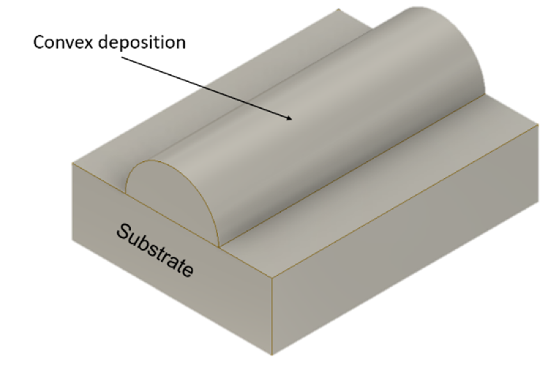
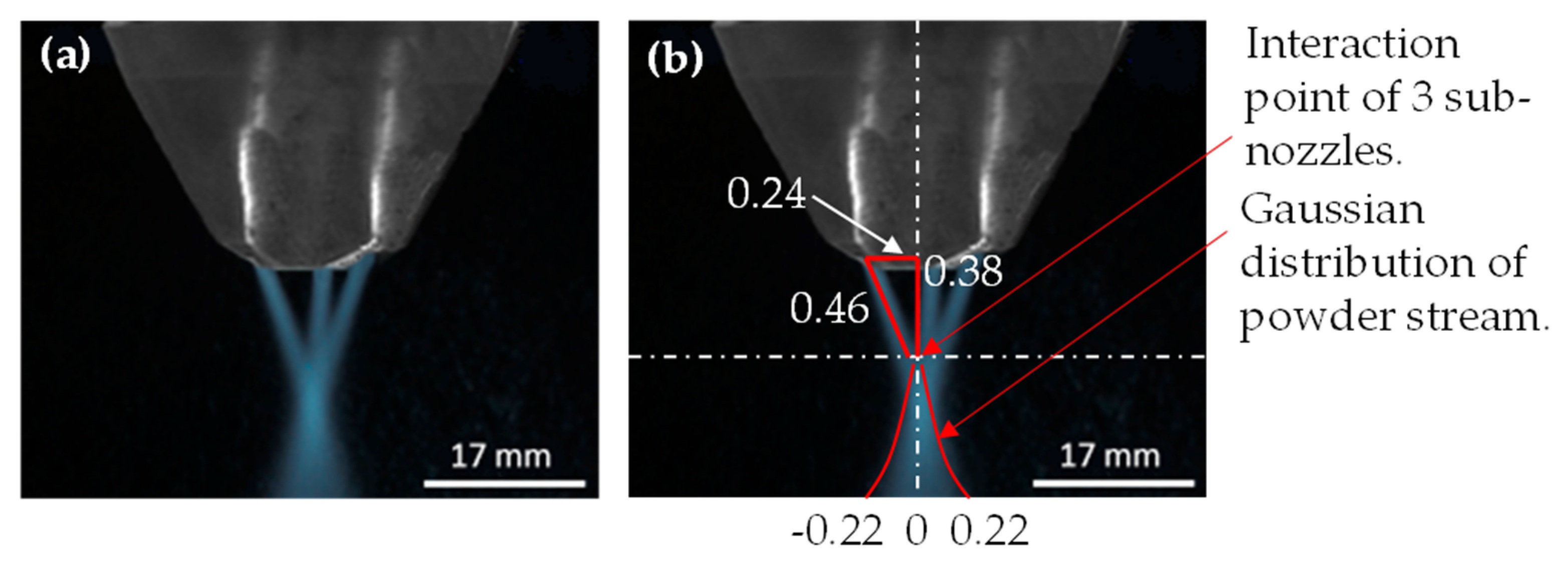
2.1. Powder Stream Distribution in the LMD Process

A schematic diagram of the three-jet powder nozzle is shown in Figure 1a,b. The powder particles, with normalized size distribution, entered in the three-jet nozzle via three sub-nozzles designated as E, F, and G, respectively. After leaving the sub-nozzles, powder particles covered a distance e, f, and g from three-sub nozzles, respectively, and travelled to the point (A), where the interaction between the laser beam and powder particles takes place. At this point, the powder stream gets a Gaussian shape.
The following assumptions have been assumed for powder flow modelling:
  • The gravitational effect, during the powder particle flow, is neglected. This assumption is reasonable as the time of flight of powder particles across the laser beam interaction zone is very short, equivalent to 25% of standoff distance [19].
  • All the powder particles are spherical. Moreover, their normalized size distribution is considered in the modelling.
  • There are two types of collisions mainly involved in the LMD process: (i) Powder debits with the powder feeder’s walls and (ii) among the powder particles. If such collisions are taken into account, various factors, including elastic motion, damping effects, friction forces due to sliding effects, powder particles’ velocity, reiterated powder flow rate, and powder debits overlapping, must be considered. It will result in a tremendous number of unknown variables and a complex system of equations, which requires a considerable amount of calculation time, iteratively. Besides, the powder debits are microparticles. It means that one should carry out investigations at the microscale to monitor the quantities mentioned above. It will result in a tedious and challenging system of equations. Moreover, there are studies [20,21,22] that show that if such collisions are ignored, the resultant flow rate will make a difference within the range of no more than 9–12%. Based on the above findings and to develop a simplified dynamic system, it is reasonable to ignore the collision between powder particles. Hence, the overlapping and all sort of collisions have been ignored throughout the deposition process.
The velocity of powder particles (vp) can be estimated as:
v p = V g 3 π r s d l ,
where Vg is the volumetric flow rate of the carrier gases as the mixture of the gases is responsible for the homogenous mixing and flow of powder particles; rs is the powder jet nozzle radius, and dl is the distance between the laser beam and powder jet nozzle centers. The constant “3” in Equation (1) supposes that 3-powder stream sub-nozzles are introduced in the modelling. The mass flow rate of the powder particles, MPE, MPF, and MPG, coming out from the three sub-nozzles (E = F = G), can be determined using the Gaussian equation [23]:
f ( x ) = q e x p ( ( z j ) 2 2 u 2 ) .
here,
q = Factor defining the starting/ending point of a physical quantity.
j = Position of the curve’s peak center.
u = Root mean square (RMS) width of the curve.
z = The universal z-coordinate.
q” depends on the powder mass flow rate ( m p ) ejecting from a powder nozzle of a radius ( r s ); “j” can be neglected as the center of the distribution should be taken in origin; “u” can be correlated to r s , and the z-axis is replaced by e, f, and g, respectively. Hence, Equation (2) transforms to:
M P E = m p π r s 2 e x p ( e 2 2 r s 2 ) .
M P F = m p π r s 2 e x p ( f 2 2 r s 2 ) .
M P G = m p π r s 2 e x p ( g 2 2 r s 2 ) .
The Gaussian powder flow, PF, from point “A” to the consolidation plane, can be calculated as:
P F = M P E + M P F + M P G 4 3 π { N ( r ) } 3 v p ρ p ,
where ρ p is powder particles’ density. Kruif et al. [24] proposed an empirical relation for the particles’ normalized size distribution, N (r), as:
N ( r ) = ( r p α 2 π ) e x p [ ( ( r p r m ) 2 α ) 2 ] .
Here, rp is the mean powder particle radius; rm is the distance between the maximum and minimum values of size distribution, and α is the width of the distribution, calculated as:
α ln ( r m 2 + 1 ) .
Substituting Equations (1), (7)–(9), (11) and (12) into Equation (10), it results in:
P F = m p π r s 2 [ e x p ( e 2 2 r s 2 ) + e x p ( f 2 2 r s 2 ) + e x p ( g 2 2 r s 2 ) ] 4 3 ρ p ( r p ln ( r m 2 + 1 ) 2 π e x p [ ( ( r p r m ) 2 α ) 2 ] ) 3 V g 3 r s d l .
e, f, and g” should be estimated/measured, experimentally.

2.2. Temperature Distribution within the Substrate in the LMD Process after Powder Addition

Figure 2 provides a schematic of the laser beam-powder stream and substrate interaction. Whenever the laser beam hits the surface of the substrate, a fraction is consumed by the powder elements and substrate to form a melt-pool. The rest is reflected by the substrate [25]. A stream of powder particles originating from multiple sources induces a conical shape with a tip directly injected into the melt-pool, produced by the high-power focused beam spot used to deposit a layer.
In the current study, the energy distribution in the laser cross-section of the beam has been considered as top-hat. It ensures a uniform energy distribution in the irradiated area. Additionally, the top-hat laser processing leads to better control of surface quality and structuring of depositions as compared to non-uniform energy distributions spots such as Gaussian beams. One should note that the Gaussian distribution of the powder in the region of the laser beam keeps significant throughout the deposition process. The deposition cross-section remains convex in shape as a substantial amount of powder is usually delivered along the center of the beam. Even though the energy distribution in the laser spot is uniform, the Gaussian distribution of the powder will produce a rounded deposition, as visible in Figure 3.
During the LMD process, laser beam shifts along the substrate’s surface, and the powder is fed coaxially. The analytical solution of the temperature distribution,   T ( x , y ) , generated by a moving heat source in a 2D substrate based on the heat conduction equation, is known [26]. In the case of the LMD process, the solution in [26] should be modified by the addition of two factors: (a) laser beam attenuation factor ( 1 ), and (b) powder particles cloud density ( Ω ), as:
T ( x , y ) = T + P 1 ξ 4 π k s R e x p ( Ω v l ( R + x ) 2 ω ) ,
where R is the distance from the laser beam to the substrate, defined as:
R = x 2 + y 2 .
Ω = P F π ( r s ) 2 v p .
Here, P, v l , ks, ω , and ξ are the laser power, laser scanning speed, and substrate’s thermal conductivity, thermal diffusivity and laser absorptivity, respectively. “ Ω ” can be varied via overlapping of the powder debits. Consequently, the laser beam energy attenuates by space propagation. Since the full consideration of attenuation is complicated, the current model is based on the particles’ shadowing while ignoring the effect of beam divergence. This is the possible explanation of why “ Ω ” should be introduced in the exponential section of Equation (14). Besides, laser energy is usually consumed, reflected, and dispersed by the powder elements as they enter into the laser beam and lead to the attenuation of energy received at the substrate’s surface [25]. The attenuated laser beam ratio, ∀1, causes significant effects upon the deposited material quality. ∀1 can be estimated by dividing the powder elements area (Ap) to laser beam area (AL):
1 = A P A L .
The area of N spherical powder particles in the powder flow can be expressed as:
A p = N π N ( r ) 2 .
Implementing the law of mass conservation, one can find that:
Mass of N powder elements fused on the sample’s surface after crossing the laser beam = Powder efficiency × Powder feed rate × Time required by the powder particles to cross the laser beam.
N 4 3 π N ( r ) 3 ρ p = 2 P F t ,
where ρp is the powder particles’ density, ∀2 is the powder efficiency. t is the time needed by the powder elements to cross the laser beam, reading as:
t = h v p = 0.25 ( S O D ) v p .
where h is the interval covered by the powder particles within the laser beam (assume h ≈ 25% of SOD). In the LMD process, standoff distance (SOD) is defined as the distance from the laser beam outlet to the substrate (Figure 2). Substituting the Equation (20) into Equation (19) provides the N value, as:
N = 3 2 P F 0.25 ( S O D ) 4 π N ( r ) 3 ρ p v p .
After substituting the Equation (21) into Equation (18), one finds:
A p = 3 P F r p 2 2 0.25 ( S O D ) 4 N ( r ) 3 ρ p v p .
The area of a circular laser beam spot on the substrate (AL) is:
A L = π r l 2 .
Dividing Equation (22) by Equation (23), one gets 1 as:
1 = 3 P F 2 0.25 ( S O D ) 4 π N ( r ) ρ p v p r l 2 .
Equation (24) gives the analytical solution of the laser beam attenuation ratio evolved/variation due to the coaxial addition of powder debits.

2.2.1. Powder Particles Heating: Inflight and within Melt-Pool

During LMD process, powder particles are subjected to heating while travelling from the powder nozzle outlet to the substrate, as well as, within the melt-pool. In the study of Yan et al. [27], the inflight heating of powder particles, only, was considered. The current research examines the heating of powder debits, both inflight and within the melt-pool. The powder particle’s heating within the melt-pool can be controlled via the laser beam scanning speed (see Equation (14)), keeping the energy density constant. The powder particle’s or substrate’s phase change strongly depends on the material properties and laser power. However, the complete melting of the powder particles is an essential requirement in the LMD process. If a particle’s or substrate’s temperature surpasses the boiling point, a strong possibility exists for metal vapor generation, as well as plasma formation. Hence, the vapor and plasma absorb the laser energy and impede the deposition process [28,29,30]. Yan et al. [27] reported a simplified analytical solution to calculate the inflight laser–powder particles interaction time needed to initiate the vaporization ( t i p h ). The final solution, which is given in [27], has been modified according to the current scenario, and becomes:
t i p h = 1 B l n ( T p s o l A T A ) 1 C l n ( T p l i q A T p s o l A ) 1 B l n ( T p b o i l A T p l i q A ) .
Here,
A = T + ξ T ( x , y ) 4 h p p .
B = h p p S p p m p p c p p .
C = h p p S p p m p p c p p + m p p L f p T p b o i l T p s o l .
h p p = N u k g 2 N ( r ) = k g ( 2 + 0.6 R e 0.5 P r 0.34 ) 2 N ( r ) .
R e = 2 ρ g N ( r ) | v g v p | μ g .
Equation (25) is useful for an alloy material, while, for pure material, Equation (25) should be transformed as [27]:
t i p h = 1 B l n ( T p m A T A ) 1 B l n ( T p b o i l A T p m A ) .
where m p p , cpp, Lfp, S p p , Tpboil, Tpm, and Tpsol are the powder particles’ mass, specific heat, latent heat of fusion, surface area, boiling, melting and solidus temperatures, respectively. T is the room temperature; k g is feeding gas’s thermal conductivity; Re is Reynolds number; h p p is the convective heat transfer coefficient in powder particles; Nu is the Nusselt number; ρ g , v g , and μ g are the gas’ density, velocity and viscosity, respectively. Note that the powder particle’s phase is predictable with time, as described by Equations (25)–(31).

2.2.2. Powder Particles’ within Melt-Pool Heating

For powder particles heating within the melt-pool, defined via laser-substrate interaction time needed to initiate the vaporization ( t s l i ); the solution of Equations (25)–(31) should be modified as:
t s l i = 1 B l n ( T s s o l A T A ) 1 C l n ( T s l i q A T s s o l A ) 1 B l n ( T s b o i l A T s l i q A ) .
Here,
A = T + ξ T ( x , y ) 4 h p s .
B = h p s S p s m p s c p s .
C = h p s S p s m p s c p s + m p s L f s T s b o i l T s s o l .
where h p s ( = 2.4 × 10 3 E s T ( x , y ) 1.61 ) is the forced convective heat transfer; m p s , cps, Lfs, S p s , Tsboil, Tsm, and Tssol are the substrate’s mass, specific heat, latent heat of fusion, surface area, boiling, melting and solidus temperatures, respectively. Equation (32) is valid for an alloy material, while for pure material Equation (32) is transformed as:
t s l i = 1 B l n ( T s m A T A ) 1 B l n ( T s b o i l A T s m A ) .
During simulation analyses, a condition has to be imposed that the particle’ inflight and within melt-pool heating times should be inferior to tiph and tsli, respectively. Note that within melt-pool heating of powder particles, the laser scanning speed in terms of substrate length and travel time has been taken into consideration, thus controlling tsli indirectly. This restriction will secure that the powder particles do not enter in the vaporization and plasma zones, and the complete melting of powder particles has been achieved, hence improving the deposition quality.

3. Materials and Methods

3.1. Analytical Computations

Ti6Al4V alloy was used for both substrate and powder feeder. The dimensions of the substrate are: a length of 1.0 m, a width of 1.0 m, and a height of 0.36 m, respectively. Table 1 collects the parameters used in computations.
The numerical simulations of Emamian et al. [34] and Duan et al. [35] in case of the deposition of Fe-TiC on the carbon steel substrate, and of 12CrNi2 alloy steel powder on 45 steel substrate, respectively, were selected for analysis of the accuracy of current analytical approach. The experimental data, for the deposition of Ti6Al4V titanium alloy powder on Ti6Al4V titanium alloy substrate, from the study of Peyre et al. [36], was also considered. The parameters used in the simulations are given in Table 2, which were adopted for current analytical simulations.
Equations (13)–(16) and (25)–(36) were used for powder flow and temperature distribution computations with the controlled phase transformation of powder debits. A Core i7, 8th Generation with 16 GB Ram computing system, was used for analytical simulations. The user-defined functions were written in a script file via MATLAB software. The computing time was approx. 40 s, which is far less than the FE-based simulations.

3.2. Experimentation

A three-jet powder stream, generated by a nozzle (Trumpf, Ditzingen, Germany) mounted on a robot (KR30HA, Kuka, Augsburg, Germany) equipped with LMD optics, was recorded via high-speed imaging camera (AX100, Photron, Tokyo, Japan). 1000 frames per second and shutter speed equal to 1/5000 s, were used to acquire the powder flow shape. The KUKA robot translates a top-hat ytterbium-doped yttrium aluminium garnet (Yb: YAG) laser beam with a wavelength equal to 1030 nm. Figure 4a shows an optical image for the powder stream distribution using a three-jet powder nozzle, which is used for the comparison between (powder stream) analytical and experimental results. The details regarding the parameters, including the intersection point of the three sub-nozzles and width of the powder stream in the Gaussian form, were determined via “Image J” software (1.53a, National Institute of Health and the Laboratory for Optical and Computational Instrumentation, Wisconsin, USA), as presented in Figure 4b.

4. Results and Discussion

Figure 5a,b presents the analytical results computed for the powder stream under a three-jet powder nozzle. It can be seen that the concentration of the stream is maximum at origin and gradually decreases from the center towards the periphery, thus generating a Gaussian shape.
Figure 6 illustrates a comparison between the experimental (see Figure 4) and computational results. Besides, the influence of the focal point position on the powder stream distribution was analyzed. A close correlation can be observed between the experimental and simulation results (Figure 6). The results indicate that the powder stream follows the Gaussian distribution at the focal plane, focal plane + 1 mm distance, and focal plane + 2 mm distance. However, the peak point of the Gaussian curve decreases while the standard deviation increases, resulting in an extended powder spread on the substrate. At the focal plane + 2.5 mm distance, the powder stream shifts from the Gaussian to the Transition stream, while at focus plane + 3 mm distance, the powder flow no longer remains in the Transition state. Instead, an Annular powder stream can be observed in Figure 6. Hence, the powder flow can be divided into three different regimes: (a) Gaussian stream, (b) Transition stream, and (c) Annular stream. This study displays a good correlation with the experimental findings given in [37].
Figure 7 shows a comparison between the current analytical modelling with the numerical simulations of Emamian et al. [34] and Duan et al. [35], and experimental results of Peyre et al. [36], with the emphasis on average peak temperature value, in case of LMD deposition process. A close correlation is observed among analytical results, numerical simulations, and experimental analysis, except the absolute mean deviation (≈10%). The possible reason for this deviation is that the material properties were considered independent of temperature change, and a point heat source was used in the modelling.
The analysis was designed to study the influence of operating parameters, including laser scanning speed (vl), laser power (P), and coaxial powder flow (PF) on temperature distribution at the substrate. The results are presented in Figure 8a–h. A Ti6Al4V substrate of 1.0 m length, 1.0 m width, and 0.36 m height was selected for the computations. The heat source was set in the middle of the substrate’s width and allowed to travel along the substrate’s length. Figure 8a,b shows the 3D and 2D temperature plots when P and vl are equal to 400 W and 0.3 m/min, respectively. The melt-pool region, mushy zone, and just solidified regime can be examined in Figure 8b. It is important to note that the melt-pool characteristics play a critical role in defining the physical properties of a clad to be deposited, while the mushy zone dynamics represent the evolution and distribution of the microstructure. Figure 8c,d displays the simulation results when vl is increased from 0.30 to 0.35 m/min, keeping P (=400 W) constant. As vl is increased, the laser to substrate interaction time decreased. As a result, there is no sufficient time for the absorption of the laser energy density by the substrate. Hence, the temperature decreases from 1650 to 1300 °C. Figure 8e,f exhibits the effect of the increase of P, from 400 to 500 W, on the temperature at the substrate’s surface. A direct relationship can be observed between P and temperature value. The influence of coaxial powder addition on the temperature value, arriving at the substrate’s surface, is visible from Figure 8g,h. One should mention that the output of PF, shown in Figure 5, is used as an input in the temperature model. The coaxial powder addition absorbs a significant portion of P that assists the powder debits in changing their phase from solid to liquid, thus playing a pivotal role in attenuating the laser energy density at the substrate. One may notice that, in the LMD process, not all the powder particles that cause the laser attenuation participate in the clad deposition. Such particles absorb the laser energy, but leave the powder cloud, thus generating a powder waste. This phenomenon also reduces the temperature value at the substrate’s surface.
As explained earlier, the powder particles undergo two types of heating: (a) inflight, and (b) within the melt-pool. The inflight heating of the powder particles can be directly controlled by the laser-powder particles’ interaction time required to initiate the vaporization ( t i p h ), while the heating of powder particles within the melt-pool can be indirectly monitored by the laser-substrate interaction time ( t s l i ) via scanning speed. For this purpose, three cases were considered when the particles heating times were: (a) Less than t i p h and t s l i , (b) equal to t i p h and t s l i , and (c) higher than t i p h and t s l i . The results are shown in Figure 9. The highest average peak temperature can be seen when particles’ and substrate’s heating times are less than t i p h and t s l i , while it continues to decrease when the particles’ and substrate’s heating times become equal or greater than t i p h and t s l i . The particles’ and substrate’s heating times play a critical role in determining the final temperature value of the substrate, hence involving the phase transformation. Excessive heating of the particles or substrate leads to the vapor and plasma formation. The generated vapors and plasma absorb a significant amount of laser energy, reducing the temperature of the substrate. It negatively affects the deposition process.
Based on the observations from Figure 8g,h, simulations were designed to study the effect of PF increment on the temperature distribution for various P values. These results are displayed in Figure 10. For a given P, with the reduction in PF, the laser beam attenuation ratio prevails the LMD deposition process. In order words, with the increase in PF, a tremendous amount of powder debits undergo the laser beam, absorbing the energy density for melting, thus resulting in the temperature drop at the substrate’s surface.
After emerging from the three sub-nozzles (Figure 1), powder debits cover a distance, and converge to the point (A), thus presenting a triangular distribution. This distribution has been verified based on experimental data (Figure 4). Point (A), defined by the distances e, f, and g in triangular distribution, is indirectly controlled by the focal point position. A variation in the focal point position changes the location of the point (A), thus, defining the regime of the powder stream distribution (Gaussian, Transition, or Annular). For this reason, an analysis has been designed to investigate the effect of different powder streams (arriving at the substrate) regimes on the temperature, as shown in Figure 11. It can be seen that the Gaussian powder stream displayed the maximum average temperature at the substrate. As the Transition or Annular stream replaces the Gaussian flow, the powder particles pass through the laser beam and absorb the laser energy but do not participate in the clad formation. It in-return causes huge powder and laser energy losses, thus, impeding the deposition process. Hence, the Gaussian powder stream regime has been identified as a preferred stream for the optimum LMD process.

5. Conclusions

This contribution involves the development of mathematical models for three-jet powder flow and temperature distribution on the substrate’s surface in the case of the LMD process. Initially, the Gaussian powder stream was simulated. Following on, the powder flow was added coaxially with the moving laser beam to analyze the effect of powder addition on the temperature distribution of the substrate. Additionally, an analytical formula to estimate the laser beam energy attenuation has been obtained. The particles’ inflight and within the melt-pool heating times were controlled to avoid excessive heating and possible transformation into vapors and plasma. The following results have been deduced based on the current model.
The focal point position plays an essential role in determining the configuration of the powder stream. An increase in the distance above the focal point position will gradually transform the powder stream from Gaussian to Transition, and next to Annular distribution.
The primary operating parameters, including laser scanning speed, laser power, and powder flow rate, play a critical role in determining the temperature value at the substrate. An inverse relationship has been found between the laser scanning speed and the powder flow rate versus temperature distribution. Besides, the laser power presented a direct relationship with the temperature value.
Attenuation phenomena occur in the LMD process due to the coaxial addition of powder debits. A significant portion of the laser beam energy is absorbed by the powder particles to transform them from solid to liquid. This attenuation ratio prevails in the LMD process as the powder flow increases, thus decreasing the laser energy density at the substrate.
The computations indicate that, if the particle’s heating temperature surpasses the boiling point, a strong possibility exists for the generation of vapor and plasma, which absorb the laser energy and impede the deposition process.
This study provides a cost- and time-effective way in the LMD process by adjusting the operating parameters to gain an optimal solution for powder debits and resultant energy.

Author Contributions

Conceptualization, M.A.M., A.C.P., and M.O.; methodology, M.A.M., A.C.P., and C.R.; software, M.A.M., and M.O.; validation, M.AM., A.C.P., C.R., I.N.M., D.C., and S.M.; formal analysis, M.A.M., A.C.P., M.O., C.R., and I.N.M.; investigation, M.A.M., D.C., and S.M.; resources, C.R., and I.N.M.; writing—original draft preparation, reviewing and editing, M.A.M., A.C.P., C.R., and I.N.M.; supervision, A.C.P., M.O., C.R., and I.N.M.; project administration and funding acquisition, A.C.P., C.R., and I.N.M. All authors have read and agreed to the published version of the manuscript.

Funding

M.A.M. has received financial support from the European Union’s Horizon 2020 (H2020) research and innovation program under the Marie Skłodowska-Curie, grant agreement No. 764935. A.C.P. and D.C. have received the funding of the PN-III-P1-1.1-TE-2016-2015 (TE136/2018) Project. S.M. was financed from the Project 25PCCDI/2018. A.C.P., C.R., M.O., and D.C. have received the financial support by Romanian Ministry of Education and Research, under Romanian National Nucleu Program LAPLAS VI – contract no. 16N/2019. C.R., and I.N.M., acknowledge with thanks the partial financial support of this work under the POC-G Contract no. 135/2016.

Acknowledgments

The authors would like to thank the DOC-3D-printing project consortium, financed by European Union’s Horizon 2020 (H2020) research and innovation program, for a fruitful discussion on laser additive manufacturing processes.

Conflicts of Interest

The authors declare no conflict of interest.

List of Symbols

A P :Area of powder particle
A L :Laser beam area
cpp:Powder particle’s specific heat
cps:Substrate’s specific heat
dl:Distance between the center of the laser beam and powder nozzle
k g :Thermal gas diffusivity
Lfp:Powder particle’s latent heat of fusion
Lfs:Substrate’s latent heat of fusion
m p p :Powder particles’ flow rate
N ( r ) :Normal distribution of powder debits
Nu:Nusselt number
P F :Gaussian powder flow
Pr:Peclét number
rs:Radius of powder nozzle
r p :Radius of the mean powder particle
Tpboil:Powder particle’s boiling temperature
Tpm:Powder particle’s melting temperature
Tpsol:Powder particle’s solidus temperature
tiph:Laser–powder particles interaction time needed to initiate the vaporization
Tsboil:Substrate’s boiling temperature
Tsm:Substrate’s melting temperature
Tssol:Substrate’s solidus temperature
Tsli:Laser–substrate interaction time needed to initiate the vaporization
T :Ambient temperature
V g :The volumetric flow rate of gases
v p :The velocity of powder particles
v l :The laser scanning speed
v g :The velocity of gas
ρ p :Powder particles’ density
ρ g :Density of gas
μ g :Viscosity of gas
1 :Laser beam attenuation ratio
2 :Powder efficiency
Ω :Powder particles’ cloud density
ω :Substrate’s thermal diffusivity
ξ :Substrate’s laser absorptivity

References

  1. Mahmood, M.A.; Popescu, A.C.; Mihailescu, I.N. Metal Matrix Composites Synthesized by Laser-Melting Deposition: A Review. Materials 2020, 13, 2593. [Google Scholar] [CrossRef] [PubMed]
  2. Pellizzari, M.; Jam, A.; Tschon, M.; Fini, M.; Lora, C.; Benedetti, M. A 3D-Printed Ultra-Low Young’s Modulus β-Ti Alloy for Biomedical Applications. Mater 2020, 13, 2792. [Google Scholar] [CrossRef] [PubMed]
  3. Zhong, C.; Pirch, N.; Gasser, A.; Poprawe, R.; Schleifenbaum, J.H. The influence of the powder stream on high-deposition-rate laser metal deposition with inconel 718. Metals 2017, 7, 443. [Google Scholar] [CrossRef] [Green Version]
  4. Chioibasu, D.; Achim, A.; Popescu, C.; Stan, G.; Pasuk, I.; Enculescu, M.; Iosub, S.; Duta, L.; Popescu, A. Prototype Orthopedic Bone Plates 3D Printed by Laser Melting Deposition. Materials 2019, 12, 906. [Google Scholar] [CrossRef] [PubMed] [Green Version]
  5. Bucă, A.M.; Oane, M.; Mahmood, M.A.; Mihăilescu, I.N.; Popescu, A.C.; Sava, B.A.; Ristoscu, C. Non-fourier estimate of electron temperature in case of femtosecond laser pulses interaction with metals. Metals 2020, 10, 606. [Google Scholar] [CrossRef]
  6. Yang, N. Concentration model based on movement model of powder flow in coaxial laser cladding. Opt. Laser Technol. 2009, 41, 94–98. [Google Scholar] [CrossRef]
  7. Lin, J. Concentration mode of the powder stream in coaxial laser cladding. Opt. Laser Technol. 1999, 31, 251–257. [Google Scholar] [CrossRef]
  8. Lin, J. Numerical simulation of the focused powder streams in coaxial laser cladding. J. Mater. Process. Technol. 2000, 105, 17–23. [Google Scholar] [CrossRef]
  9. Pan, H.; Liou, F. Numerical simulation of metallic powder flow in a coaxial nozzle for the laser aided deposition process. J. Mater. Process. Technol. 2005, 168, 230–244. [Google Scholar] [CrossRef]
  10. Pan, H.; Sparks, T.; Thakar, Y.D.; Liou, F. The investigation of gravity-driven metal powder flow in coaxial nozzle for laser-aided direct metal deposition process. J. Manuf. Sci. Eng. Trans. ASME 2006, 128, 541–553. [Google Scholar] [CrossRef]
  11. Pinkerton, A.; Pinkerton, A.J.; Li, L. A verified model of the behaviour of the axial powder stream concentration from a coaxial laser cladding nozzle. Laser Inst. Am. 2002, 2002, 165528. [Google Scholar] [CrossRef]
  12. Pinkerton, A.J.; Lin, L. Modelling powder concentration distribution from a coaxial deposition nozzle for laser-based rapid tooling. J. Manuf. Sci. Eng. Trans. ASME 2004, 126, 33–41. [Google Scholar] [CrossRef]
  13. Kizaki, Y.; Azuma, H.; Yamazaki, S.; Sugimoto, H.; Takagi, S. Phenomenological studies in laser cladding Part I: Time-resolved measurements of the absorptivity of metal powder. Jpn. J. Appl. Phys. 1993, 32, 205–212. [Google Scholar] [CrossRef]
  14. Liu, J.; Li, L. Effects of powder concentration distribution on fabrication of thin-wall parts in coaxial laser cladding. Opt. Laser Technol. 2005, 37, 287–292. [Google Scholar] [CrossRef]
  15. Tabernero, I.; Lamikiz, A.; Ukar, E.; López De Lacalle, L.N.; Angulo, C.; Urbikain, G. Numerical simulation and experimental validation of powder flux distribution in coaxial laser cladding. J. Mater. Process. Technol. 2010, 210, 2125–2134. [Google Scholar] [CrossRef]
  16. Galarraga, H.; Warren, R.J.; Lados, D.A.; Dehoff, R.R.; Kirka, M.M.; Nandwana, P. Effects of heat treatments on microstructure and properties of Ti-6Al-4V ELI alloy fabricated by electron beam melting (EBM). Mater. Sci. Eng. A 2017, 685, 417–428. [Google Scholar] [CrossRef] [Green Version]
  17. Toyserkani, E.; Khajepour, A.; Corbin, S. 3-D finite element modeling of laser cladding by powder injection: Effects of laser pulse shaping on the process. Opt. Lasers Eng. 2004, 41, 849–867. [Google Scholar] [CrossRef]
  18. Cao, X.; Ayalew, B. Control-oriented MIMO modeling of laser-aided powder deposition processes. In Proceedings of the American Control Conference, Chicago, IL, USA, 1–3 July 2015; Institute of Electrical and Electronics Engineers Inc.: Piscataway, NJ, USA, 2015; pp. 3637–3642. [Google Scholar]
  19. Huang, Y.-L.; Liu, J.; Ma, N.-H.; Li, J.-G. Three-dimensional analytical model on laser-powder interaction during laser cladding. J. Laser Appl. 2006, 15, 42. [Google Scholar] [CrossRef]
  20. Crowe, C.T.; Schwarzkopf, J.D.; Sommerfeld, M.; Tsuji, Y. Multiphase Flows with Droplets and Particles, 2nd ed.; CRC Press, Taylor & Francis Group: Boca Raton, FL, USA, 2012; ISBN 978-1-4398-4051-1. [Google Scholar]
  21. Liu, C.Y.; Lin, J. Thermal processes of a powder particle in coaxial laser cladding. Opt. Laser Technol. 2003, 35, 81–86. [Google Scholar] [CrossRef]
  22. Volpp, J.; Prasad, H.S.; Kaplan, A. Behavior of heated powder particles on solid surfaces. Procedia Manuf. 2018, 25, 365–374. [Google Scholar] [CrossRef]
  23. Forbes, C.; Evans, M.; Hastings, N.; Peacock, B. Normal (Gaussian) Distribution. In Statistical Distributions; John Wiley & Sons, Inc.: Hoboken, NJ, USA, 2010; pp. 143–148. [Google Scholar]
  24. De Kruif, C.G.; Huppertz, T.; Urban, V.S.; Petukhov, A.V. Casein micelles and their internal structure. Adv. Colloid Interface Sci. 2012, 171, 36–52. [Google Scholar] [CrossRef] [PubMed]
  25. Toyserkani, E.; Khajepour, A.; Corbin, S. Laser Cladding; CRC Press, Taylor & Francis Group: Boca Raton, FL, USA, 2017; ISBN 0849321727. [Google Scholar]
  26. Carslaw, H.; Jaeger, J. Conduction of Heat in Solids; Oxford University Press: Oxford, UK, 1959. [Google Scholar]
  27. Yan, J.; Battiato, I.; Fadel, G.M. A Mathematical Model-Based Optimization Method for Direct Metal Deposition of Multimaterials. J. Manuf. Sci. Eng. 2017, 139. [Google Scholar] [CrossRef]
  28. Vetter, P.A.; Fontaine, J.; Engel, T.; Lagrange, L.; Marchione, T. Characterization Of Laser-materialInteraction During Laser Cladding Process. WIT Trans. Eng. Sci. 1970, 2. [Google Scholar] [CrossRef]
  29. Antipas, G.S.E. Experimental and first principles assessment of plasma attenuation during laser treatment of an Al alloy. Trans. Inst. Met. Finish. 2015, 93, 53–56. [Google Scholar] [CrossRef]
  30. Luo, Y.; Tang, X.; Lu, F.; Chen, Q.; Cui, H. Spatial distribution characteristics of plasma plume on attenuation of laser radiation under subatmospheric pressure. Appl. Opt. 2015, 54, 1090–1096. [Google Scholar] [CrossRef]
  31. ASM Material Data Sheet. Available online: http://asm.matweb.com/search/SpecificMaterial.asp?bassnum=MTP641 (accessed on 23 February 2020).
  32. Mirkoohi, E.; Ning, J.; Bocchini, P.; Fergani, O.; Chiang, K.-N.; Liang, S. Thermal Modeling of Temperature Distribution in Metal Additive Manufacturing Considering Effects of Build Layers, Latent Heat, and Temperature-Sensitivity of Material Properties. J. Manuf. Mater. Process. 2018, 2, 63. [Google Scholar] [CrossRef] [Green Version]
  33. Guo, Y.; Hu, S.; Dong, D.; Wang, W.; Zhang, D. Numerical simulation in the laser energy absorption behavior of Ti6Al4V powder materials during SLM. In Advanced Laser Processing and Manufacturing II; Liu, J., Hong, M., Xiao, R., Eds.; SPIE: Bellingham, WA, USA, 2018; Volume 10813, p. 37. [Google Scholar]
  34. Emamian, A.; Alimardani, M.; Khajepour, A. Correlation between temperature distribution and in situ formed microstructure of Fe-TiC deposited on carbon steel using laser cladding. Appl. Surf. Sci. 2012, 258, 9025–9031. [Google Scholar] [CrossRef]
  35. Duan, C.; Zhou, J.; Luo, X.; Zhao, M. Numerical Simulation of Temperature Field of 12crni2 by Laser Melting Deposition. Conf. Ser. Mater. Sci. Eng. 2019, 667. [Google Scholar] [CrossRef] [Green Version]
  36. Peyre, P.; Dal, M.; Ebastien Pouzet, S.; Castelnau, O.; Ebastien Pouzet, S. Simplified numerical model for the laser metal deposition additive manufacturing process. J. Laser Appl. 2017, 29, 1–8. [Google Scholar]
  37. Liu, Z.; Zhang, H.C.; Peng, S.; Kim, H.; Du, D.; Cong, W. Analytical modeling and experimental validation of powder stream distribution during direct energy deposition. Addit. Manuf. 2019, 30, 100848. [Google Scholar] [CrossRef]
Figure 1. Graphical representation of a three-jet powder nozzle: (a) 3D, and (b) 2D.
Metals 10 01113 g001
Figure 2. Schematic of the laser melting deposition (LMD) process.
Metals 10 01113 g002
Figure 3. Convex shaped deposition at substrate’s surface.
Metals 10 01113 g003
Figure 4. A three-jet powder stream distribution (a) experimental image and (b) image processed via “Image J” software; all units are in millimeter (mm).
Metals 10 01113 g004
Figure 5. Ti6Al4V alloy gaussian powder stream distribution plots (a) 3D and (b) 2D.
Metals 10 01113 g005
Figure 6. Comparison of Ti6Al4V titanium alloy powder flow experimental and simulation results: Influence of the focal point position on powder stream distribution regimes.
Metals 10 01113 g006
Figure 7. Comparison of current analytical with (a) numerical simulation for Fe-TiC depositions on the carbon steel substrate [34], (b) numerical simulation of 12Cr Ni2 alloy steel powder depositions 45 steel substrate [35], and (c) experimental results for Ti6Al4V titanium alloy powder deposition on Ti6Al4V titanium alloy substrate [36].
Metals 10 01113 g007
Figure 8. Temperature profiles for Ti6Al4V alloy when (a) P = 400 W, vl = 0.3 m/min, (b) 2D plot of (a), (c) P = 400 W, vl = 0.35 m/min, (d) 2D plot of (c), (e) P = 500 W, vl = 0.3 m/min, (f) 2D plot of (e), (g) P = 400 W, vl = 0.3 m/min with the co-axial addition of powder debits, and (h) 2D plot of (g).
Metals 10 01113 g008
Figure 9. Influence of particles’ and substrate’s heating times on temperature of the substrate for Ti6Al4V alloy deposition.
Metals 10 01113 g009
Figure 10. Effect of Ti6Al4V alloy powder flow (PF) and laser power (P) on the average maximum temperature of the substrate.
Metals 10 01113 g010
Figure 11. Effect of Ti6Al4V alloy powder stream on average maximum temperature at the substrate when P = 400 W, vl = 0.3 m/min, and PF = 5.0 (g/mm3).
Metals 10 01113 g011
Table 1. Thermo-physical properties of Ti6Al4V alloy powder deposition on the Ti6Al4V alloy substrate [31,32,33].
Parameter NameValue (Units)
Thermal coefficient for radiation5.67 × 10−8 (W/m2. °C4)
Heat transfer coefficient 24 (W/m2. °C)
Room temperature25 (°C)
Liquidus temperature1654.85 (°C)
Solidus temperature1604.85 (°C)
Thermal conductivity0.067 (W/m. °C)
Specific heat capacity526 (J/kg. °C)
Density4420 (kg/m3)
Viscosity4.0 × 10-3 (kg/m.s)
Latent heat 2.0 × 10⁵ (J/kg)
Powder particles’ laser absorption coefficient0.70
Laser spot size800 (µm)
Powder efficiency0.40
Standoff distance17 (mm)
Powder particles’ diameter in the normalized distribution43–106 (µm)
Table 2. Parameters opted for temperature distribution analytical simulations.
Parameter Name (Units)For Numerical Simulations: Fe-TiC Depositions on the Carbon Steel Substrate [34]For Numerical Simulations: 12Cr Ni2 Alloy Steel Powder Depositions 45 Steel Substrate [35]For Experimental Analysis: Ti6Al4V Titanium Alloy Powder Deposition on Ti6Al4V Titanium Alloy Substrate [36]
Laser power (W)885 1800 400
Scanning speed (mm/s)2.05.06.67
Powder feeding rate (g/min)4.011.02.5
Powder jet radius (m)1.30 × 10⁻³ 1.60 × 10−31.70 × 10−3
Laser beam radius (m)1.25 × 10⁻³ 1.50 × 10−31.05 × 10−3

