Abstract
The majority of literature sources dedicated to dissimilar Al-Cu friction stir welding testifies to the formation of intermetallic compounds (IMC) according to diffusion-controlled reactions, i.e., without liquation on the Al/Cu interfaces. Fewer sources report on revealing Al-Cu eutectics, i.e., that IMCs are formed with the presence of the liquid phase. This work is an attempt to fill the gap in the results and find out the reasons behind such a difference. Structural-phase characteristics of an in-situ friction stir processed (FSP) Al-Cu zone were studied. The single-pass FSPed stir zone (SZ) was characterized by the presence of IMCs such as Al2Cu, Al2Cu3, AlCu3, Al2MgCu, whose distribution in the SZ was extremely inhomogeneous. The advancing side SZ contained large IMC particles as well as Al(Mg,Cu) solid solution (SS) dendrites and Al-Al2Cu eutectics. The retreating side SZ was composed of Al-Cu solid solution layered structures and smaller IMCs. Such a difference may be explained by different levels of heat input with respect to the SZ sides as well as by using lap FSP instead of the butt one.
1. Introduction
Metallomatrix composite surface materials modified using friction stir processing (FSP) are state-of-the-art materials, which are intended to combine high strength, wear resistance with high ductility and fatigue resistance of a core metal such as an aluminum alloy [1]. The FSP was originally a process used for surface structural modification, i.e., grain refining, which then was adapted to prepare the metallic matrix composites (MMC) surface coatings by means of introducing various reinforcement particles and admixing them to the matrix metal [1,2,3,4,5,6,7,8,9,10]. The FSP utilizes the friction-generated heat for plasticizing the matrix metal, which then is transferred to the rear zone by means of tool rotation and translational motion. The plasticized metal flows along a rather complex trajectory and its adhesion to the tool plays a great role in the metal transfer and stirring. The intense stirring serves to ensure homogeneous distribution of hard particles throughout the stir zone (SZ), and the FSP process parameters such as tool rotation rate and travel speed can be varied to find an optimal degree of mixing as well as temperature conditions.
The hard particles may be introduced into the stirred metal directly [7,8,9,11,12,13] or form in-situ inside the metal [14,15,16,17,18] by means of solid-state reactions between the admixed components, between the admixed components and the matrix or between the dissimilar metals processed. The FSP preparation of hybrid composites with the use of in-situ reactions shows up some advantages over those obtained using commercially available reinforcement particles. The first advantage is that in-situ reactions allow us to obtain finer and more homogeneously distributed reinforcing particles [17]. The second advantage is that either coherent or semicoherent boundaries may form between these in-situ prepared particles and the matrix [10,15,19] and therefore more thermodynamically stable and strong particle/matrix interfaces are feasible [20]. The literature sources were analyzed to show that many experimental compositions such as Al7075-Ti-6Al-4V [14]; Al1050-Ni-Ti-C [15]; Al-SiC [15,21]; Al6061-Fly ash [18]; Al1050-Fe2O3-Al [17]; Al-1050-Cu [16]; Al-Ni; Al-Nb [22]; Al-graphene [13,21,22] were subjected to FSP in order to prepare the in-situ MMCs.
Commonly, copper is one of the widely used and efficient metals to carry out FSP on aluminum alloys and thus obtain the MMCs reinforced with Al-Cu intermetallic particles [23]. Intermetallic Cu-Al particle reinforced MMCs may be fabricated using friction stir welding (FSW) on dissimilar metals [24,25,26,27], multilayer friction stir brazing [28], die-casting, powder metallurgy, etc.
The effect of different tool configurations on friction heat generation, metal flow and formation of intermetallic layers was studied in friction stir spot welding of dissimilar Cu and Al metals [24]. It was shown that thin intermetallic layers were formed from compounds such as CuAl2, CuAl and Al4Cu9. Intermetallic compound layers consisting of CuAl2 and Al4Cu9 were found at the Cu-Al boundaries along with hot cracking during butt friction stir welding of Cu and Al [25].
AA6061-T6 plates were welded with a copper plate inserted in the butt line between two AA6061 plates and the resulting stir zone structure contained CuAl2 and Al4Cu9 intermetallic particles [26]. Both intermetallic particles and interlayers were formed during butt FSW on Cu and Al plates [27]. Ultrasound treatment was used to reduce the thickness of intermetallic layers formed with FSW [29].
Only a few publications were devoted to obtaining the Al-Cu composites using the FSP admixing the Cu powder. Hsu et al. [30] demonstrated that homogeneous Al-Al2Cu MMC with Young modulus 88 ± 8 GPa, yield stress 450 MPa, ultimate stress 650 MPa and 0.15 plasticity may be obtained using FSP on Al-15 at.% Cu green samples compacted at 225 MPa.
It has been reported [16] that when pure copper powders were FSP admixed to aluminum plates at the tool travel speed 1.66 mm/s and rotation rate 750 rpm, the resulting intermetallic particles were CuAl2 ones. Increasing the FSP pass number and, in particular, the FSP tool rotation rate to 1000 and even to 1500 rpm resulted in precipitation of mainly Al-Cu and Al4Cu9 intermetallics. On the contrary, only Al2Cu precipitates were found in the aluminum irrespective of the FSP pass number [31].
This work was focused on studying the specificity of in-situ synthesis of Al-Cu intermetallic particles by means of lap FSP on a copper and aluminum alloy.
2. Materials and Methods
The hot-rolled AA5056 sheets were cut into 200 mm × 60 mm × 5 mm samples. C11000 copper sheets were cut into 200 mm × 60 mm × 2 mm samples. Chemical compositions of the alloy and copper sheets are shown in Table 1.

Table 1.
Chemical composition of A5056 and C11000 plates.
Friction stir processing was carried out with the use of the FSW machine (Sespel, Cheboksary, Russian) at the Institute of Strength Physics and Materials Science of Siberian Branch of Russian Academy of Sciences (Tomsk, Russian) (Figure 1). A truncated cone flute FSW tool with a 2.5 mm height pin and top and bottom diameters of 6 and 4 mm, respectively, was used. The tool shoulder diameter was 12 mm. The FSW tool inclination angle was 3°. The FSW parameters were as follows: rotation rate 500 rpm, travel speed 90 mm/min, plunging force 12,000 N. This set of parameters was found to be optimal as follows from previous experimenting [32]. The FSW tool penetration was 2.5 mm.
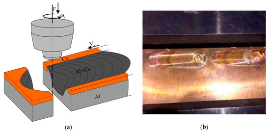
Figure 1.
Scheme of FSP on C11000/A5056 sandwich (a) and single-pass FSP seams (b).
The FSPed samples were cut using electric dischage method (EDM) in planes perpendicular to the joint centerline to obtain specimens for examination and tests (Figure 1a). The microstructural evolution was examined on polished and etched section views prepared according to ASTM standards and visualized using optical microscopes Altami Met 1S (LLC Altami, Sankt Petersburg, Russian) and Olympus LEXT 4100 (Olympus NDT, Inc., Waltham, MA, USA) as well as scanning electron microscopy (SEM) and transmission electron microscopy (TEM) instruments Zeiss LEO EVO 50 (Carl Zeiss, Oberkochen, Germany) and JEOL-2100 (JEOL Ltd., Akishima, Japan), respectively. The chemical composition of precipitates was controlled using an EDS attachment to TEM.
The mean particle sizes were determined using the linear intercept method. Perfect stoichiometric compound component ratios were used to identify intermetallics found in the stir zone and analyzed with EDS. Using an X-ray diffraction (XRD) instrument XRD-7000S (Shimadzu, Kyoto, Japan) operated at 35 kV, 24 mA, irradiation was applied for identifying the Al-Cu phases. Microhardness profiles were obtained using a microhardness tester Duramin 5 (Struers A/S, Ballerup, Denmark) at 100 g load and a dwell time of 10 s.
3. Results
The macrostructure view of the FSW seam cross-sectional area allows us to observe composite structures in both the stirring zone (SZ) and thermomechanically affected zone (TMAZ) (Figure 2a). Both central and bottom areas of the SZ located close to the advancing side of the seam reveal discontinuities which may be shrinkage pores formed during the formation of Cu-Al intermetallics. The stir zone is characterized by alternating Al/Cu layers in its bottom part (Figure 2b) as well as Al-Cu solid solution and intermetallic compound (IMC) layers (Figure 2c). The large IMCs areas are seen on the retreating side of the SZ (Figure 2a).
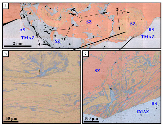
Figure 2.
The FSPed SZ cross-sectional zones and Cu-Al intermixed areas: 1—defects; 2—solid solution (SS) areas; 3—IMC areas; 4—cracking at the advancing side; AS—advancing side; RS—retreating side; (a) the SZ macrostructure; (b) alternating SS and IMC layers; (c)—aluminum inflow pattern.
The XRD pattern in Figure 3 reveals the phases as follows: Al, Cu, Al2Cu, Al2Cu3, AlCu3, Al2MgCu and thus suggests that in-situ Al-Cu reactions have occurred. Nevertheless, there are large IMC-free areas composed of unreacted Cu and Al. Formation of Al2Cu IMCs on the Cu/Al interfaces during FSW was noted in the majority of works dedicated to dissimilar FSW [24,25,26,27,29,30].
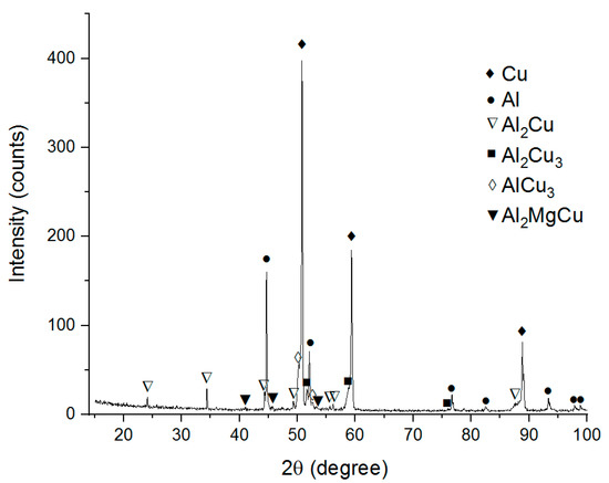
Figure 3.
The XRD pattern of the Cu-Al stirring zone metal.
The composite structure of Al-Cu SZ does not look structurally homogeneous since it includes many different phases and microstructures (Figure 4).
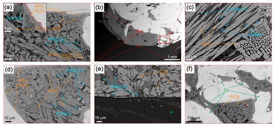
Figure 4.
The SEM BSE images of SZ microstructures after a single-pass FSP on the Al-Cu sandwich: (a) SS/IMC interface; (b) stir zone macrostructures; (c) column IMCs; (d) IMCs of different compositions; (e) substrate/stir zone boundary; (f) mixed IMC + SS zone.
The IMC layers formed at the Al/Cu interfaces on the Cu-rich side of SZ are composed of 2 to 5 μm in size Al2Cu3 and AlCu3 IMCs (Figure 4a,d). The mean size of the Al2Cu3 and AlCu3 particles in these IMCs is about 300 nm. The presence of these phases is confirmed by the results of XRD (Figure 3), TEM (Figure 5) and EDS (Table 2, spectra 4–7).
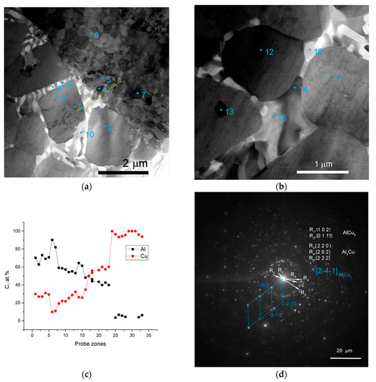
Table 2.
Chemical compositions of phases shown in Figure 5.
The interfaces between fine-crystalline copper and IMCs are shown in Figure 5a as well as Al/Al2Cu eutectics located in between the Al2Cu particles. The selected area electron diffraction (SAED) pattern obtained from the area in Figure 5a shows the reflections, which can be identified as those belonging to AlCu3, Al2Cu and Al2Cu3 (Figure 5d). Analyzing the EDS spectra and taking into account the ideal stoichiometric formulas of the IMCs detected, the theoretical compositions of them were determined and are presented in Table 2 and Table 3. It is worthwhile noting that IMCs composed of Al2Cu3 and AlCu3 particles are inherent to all Al/Cu alternating layers (Figure 4a,d–f).
Table 3.
Chemical compositions of phases shown in Figure 6.
When looking at the Al-rich part of the SZ, more aluminum-rich phases are formed there according to reactions as follows:
Al2Cu3 + 5Al → Al + 3Al2Cu
AlCu3 + 6Al → Al + 3Al2Cu.
The microstructure of this zone is composed of SS Al(Cu,Mg) and Al2Cu particles as confirmed by the EDS and SEM (Figure 4 and Figure 6, Table 3).
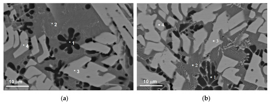
Figure 6.
The SEM BSE images of microstructures in the SZ (a,b), which contain SS Al(Cu,Mg), Al2Cu and Al2MgCu particles as detected using the EDS probe on microstructure components denoted 1, 2, 3, 4.
The solid solution in this zone contains up to 5.7 at.% Cu and 3.1 at.% Mg in Al, i.e., it can be referred to as an Al(Cu,Mg) phase as shown by the EDS spectra in Figure 6 and Table 3. These Al(Cu,Mg) particles are dendrites and have a mean size of 11.8 μm (Figure 6). Such a dendritic shapes may be evidence in favor of heterogeneous nucleation and growth in a liquid phase.
Two different sorts of CuAl2 particles are formed in the SZ (Figure 4a,c–f; Figure 6) such as thin 7 × 50 μm2 area platelets and the fine ones found in eutectics. Figure 5c shows an EDS profile along the line shown in Figure 5a, i.e., a transition zone from IMC to the Al-Al2MgCu eutectics and then to the recrystallized fine-grained copper.
An intermetallic Al-Al2MgCu eutectic phase was also EDS detected in the middle of SZ (Table 2 and Table 3) (Figure 3, Figure 4a, Figure 6).
The macroscopic FSP track cross-sectional area in Figure 7a shows lines along which the microhardness number profiles (Figure 7b,c) were obtained. Both Figure 7b and Figure 7c demonstrate that microhardness profiles obtained in two perpendicular directions allow for the differentiation between the matrix and IMCs, and, in fact, reveal the SZ structural inhomogeneity, which means a lack of equality in strength. The microhardness of IMCs is by a factor of 2 to 5 higher than those of the base metals.
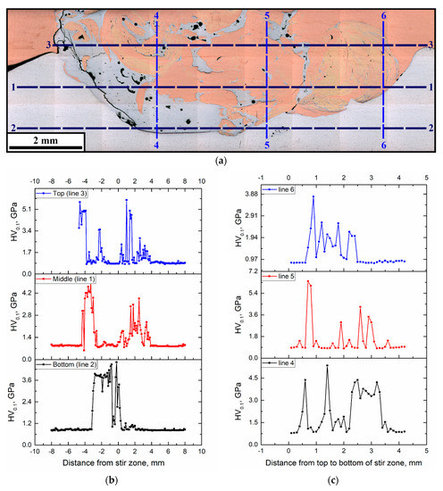
Figure 7.
Microhardness profile measurement lines (a) and microhardness profiles along horizontal (1, 2, 3) (b) and vertical (4, 5, 6) directions (c).
4. Discussion
The results of this work clearly show the inhomogeneous structure of the stir zone composed of copper, aluminum, Al-Mg-Cu solid solution and a set of different morphology IMCs. The FSP is a strong nonequilibrium process so that the microstructural evolution of the processed metal is determined by a variety of external factors such as heat generation, mechanical stirring (deformation), heat removal as well as internal process factors such as adhesion-assisted or quasi-viscous transfer of metal portions to the zone behind the tool, dynamic recrystallization, diffusion-controlled precipitation and mechanochemical solid-state reactions. The Cu-Al system is capable of forming intermetallic compounds with a high exothermic effect so that a thin liquid phase layer may form at the Al/Cu interface due to contact melting. Such a phenomenon leads to a fast liquid-phase synthesis of coarse IMC layers and particles, especially when fusion methods are used to obtain the Cu-Al alloys. At the same time, only diffusion-controlled formation of IMCs is possible when the process temperatures are low enough. In FSP on Cu-Al, the temperatures in the stir zone are in the range 400–500 °C [31], i.e., lower than the eutectic temperature TE = 548.2 °C and no Al-Cu eutectics were detected in this work. All IMCs were formed by means of diffusion-controlled precipitation from a supersaturated solid solution obtained in FSP according to the model suggested by Pretorius et al. [33]. According to such a model, the effective heat of formation () of phases at the binary Al-Me system interfaces can be determined as follows:
where is the effective heat of formation of i-phase, is the enthalpy of formation change for phase i; is the effective concentration of the limiting element at the interface; is the concentration of the limiting element in the compound. Taking into account that the effective Gibbs free energy change () in case of an i-phase formation is determined as:
Table 4 shows the results of calculating the Gibbs free energy changes corresponding to the formation of all Al-Cu binary system phases. It can be noted that only negative values were obtained, thus, determining the feasibility of the IMC nucleation and growth. The maximum absolute values and were found for Al2Cu3 and AlCu3, i.e., these phases were the first ones to form at the Cu/Al interfaces. Therefore, those phases were detected in this work as small particles on the Cu-rich side of the image in Figure 4a. The next phase to form was Al2Cu with .
Table 4.
Effective Gibbs free energy changes at Cu-Al interfaces at 450 °C.
It should be noted that, in general, the diffusion-controlled Al-Cu interaction may lead to the formation of a variety of IMC phases as dependent on Cu-content, sort of source materials (sheet or powders), etc. Since copper and aluminum sheets were used in this work, the local Cu-content may be as high as 40 vol.% due to intense stirring and transfer then three binary phases were formed such as Al2Cu3, AlCu3, and Al2Cu. However, it was reported [16,30,31,34] that only a single Al2Cu phase was formed when FSP admixing the pure copper powders at a concentration of ≤15 at.% and in-situ synthesizing the Al-Cu composite. Using the Pretorius model [33], it was experimentally established [31] that Al2Cu had to be the first phase to form since its Gibbs free energy change of formation was the most negative value of all other phases as determined for a Cu at.% concentration corresponding to the lowest temperature eutectic.
On the other hand, eutectic structures were observed during friction stir spot welding of AA5083 to copper [36]. The majority of papers devoted to studying the dissimilar Al-Cu butt FSWed SZ did not show any presence of eutectics in distinction to the friction stir spot welding (FSSW) SZ microstructures. The reason is the higher heat removal into a copper sheet in the case of butt FSW as compared to FSSW or lap FSW. Preferential localization of IMCs on the advancing side of the SZ may be related to more intense admixing between aluminum and copper layers (particles) detached off the parent metals and transferred to the stagnation (trailing) zone behind the tool closer to the advancing side where these layers adhere to the already deposited layers; finally, recrystallize and grow the IMCs at rest. Closer to the retreating side these layers are stirred by the tool and deformed so that the strain dissolution of the IMCs prevails over their precipitation, thus, facilitating the formation of the solid solution only. Such a consideration is based on the adhesion-assisted transfer of metal during FSP when a transferred portion (layer) of metal first adheres to the FSW tool, then is transferred to the stagnation zone behind the tool, and adheres back to the previously transferred layers [37].
It is suggested also that more heat is generated on the advancing side as compared to that of the retreating side [38]. This factor may provide higher heating and better conditions for the contact melting between copper and aluminum transferred layers.
The combined effect of severe plastic deformation and heating provided the formation of a row of Al-Cu phases. There are a number of phases whose morphology allows for the suggestion of their origin from a liquid phase. First of all, those phases were Al-Al2Cu eutectics and Al-Mg-Cu solid solution dendrites that formed near the IMC large particles as a result of depleting these zones of copper. Such a scenario is inherent to the advanced side of the SZ zone.
Reaction-diffusion controlled nucleation and growth of IMC smaller particles is inherent to the mechanically alloyed multilayer metal on the retreating side of the SZ. Friction stir processing in this zone resulted in the formation of a Cu-Al mechanical alloy (bronze) which differed also from both parent metals by its color. The smaller IMCs are found in the interlayer spaces whereas the in the main phase there is the Al-Mg-Cu SS.
5. Conclusions
Microstructural evolution and phase composition of stir zone in-situ obtained using friction stir processing on an Al-Cu bimetal workpiece were studied:
- The single-pass FSP on Cu-Al bimetal plate resulted in the formation of a stir zone with inhomogeneous distribution of intermixed phases identified as unreacted metals, intermetallic phases such as Al2Cu, Al2Cu3, AlCu3, Al2MgCu, Al(Mg,Cu) solid solution and Al-Al2Cu eutectics.
- Large IMC particles as well as Al-Al2Cu eutectics and Al-Mg-Cu solid solution dendrites were preferentially located on the advancing side of the SZ zone, while the retreating side zone of SZ was characterized by the presence of Al-Cu solid solution layered structures and smaller IMC particles located between the solid solution layers.
- The microhardness profiles measured across the SZ digitally mirrors the inhomogeneity of the phase distribution there. The microhardness of IMC zones is by a factor of 2–5 higher than that of copper.
- The IMC areas containing the eutectics and solid solution dendrites, which might originate from Al-Cu liquation, are characterized by large irregular shaped shrinkage pores.
Author Contributions
A.Z., A.C., A.G., T.K., S.F., N.S. performed sample preparation and characterization; A.C., E.K. and S.T. performed project administration, conceptualization, supervision, designed the experiments, and analyzed the data; A.Z., A.C. and S.T. wrote this paper. All authors have read and agreed to the published version of the manuscript.
Funding
Sample preparation and processing were funded by the Government research assignment for ISPMS SB RAS, project No. III.23.2.4. Characterization of microstructures and phases obtained using dissimilar FSP on copper and aluminum alloy was performed with financial support from RSF Grant No. 19-79-00136.
Conflicts of Interest
The authors declare no conflict of interest.
References
- Sudhakar, M.; Rao, C.H.S.; Saheb, K.M. Production of Surface Composites by Friction Stir Processing-A Review. Mater. Today Proc. 2018, 5, 929–935. [Google Scholar] [CrossRef]
- Padhy, G.K.; Wu, C.S.; Gao, S. Friction stir based welding and processing technologies-processes, parameters, microstructures and applications: A review. J. Mater. Sci. Technol. 2018, 34, 1–38. [Google Scholar] [CrossRef]
- Rao, A.G.; Ravi, K.R.; Ramakrishnarao, B.; Deshmukh, V.P.; Sharma, A.; Prabhu, N.; Kashyap, B.P. Recrystallization Phenomena During Friction Stir Processing of Hypereutectic Aluminum-Silicon Alloy. Metall. Mater. Trans. A 2013, 44, 1519–1529. [Google Scholar] [CrossRef]
- Sun, H.; Yang, S.; Jin, D. Improvement of Microstructure, Mechanical Properties and Corrosion Resistance of Cast Al--12Si Alloy by Friction Stir Processing. Trans. Indian Inst. Met. 2018, 71, 985–991. [Google Scholar] [CrossRef]
- Zhao, H.; Pan, Q.; Qin, Q.; Wu, Y.; Su, X. Effect of the processing parameters of friction stir processing on the microstructure and mechanical properties of 6063 aluminum alloy. Mater. Sci. Eng. A 2019, 751, 70–79. [Google Scholar] [CrossRef]
- Zahmatkesh, B.; Enayati, M.H. A novel approach for development of surface nanocomposite by friction stir processing. Mater. Sci. Eng. A 2010, 527, 6734–6740. [Google Scholar] [CrossRef]
- Bourkhani, R.D.; Eivani, A.R.; Nateghi, H.R. Through-thickness inhomogeneity in microstructure and tensile properties and tribological performance of friction stir processed AA1050-Al2O3 nanocomposite. Compos. Part B Eng. 2019, 174, 107061. [Google Scholar] [CrossRef]
- Abraham, S.J.; Dinaharan, I.; Selvam, J.D.R.; Akinlabi, E.T. Microstructural characterization of vanadium particles reinforced AA6063 aluminum matrix composites via friction stir processing with improved tensile strength and appreciable ductility. Compos. Commun. 2019, 12, 54–58. [Google Scholar] [CrossRef]
- Jain, V.K.S.; Varghese, J.; Muthukumaran, S. Effect of First and Second Passes on Microstructure and Wear Properties of Titanium Dioxide-Reinforced Aluminum Surface Composite via Friction Stir Processing. Arab. J. Sci. Eng. 2019, 44, 949–957. [Google Scholar] [CrossRef]
- Huang, C.W.; Aoh, J.N. Friction stir processing of copper-coated SiC particulate-reinforced aluminum matrix composite. Materials (Basel) 2018, 11, 599. [Google Scholar] [CrossRef]
- Prabhu, M.S.; Perumal, A.E.; Arulvel, S.; Issac, R.F. Friction and wear measurements of friction stir processed aluminium alloy 6082/CaCO3 composite. Measurement 2019, 142, 10–20. [Google Scholar] [CrossRef]
- Barati, M.; Abbasi, M.; Abedini, M. The effects of friction stir processing and friction stir vibration processing on mechanical, wear and corrosion characteristics of Al6061/SiO2 surface composite. J. Manuf. Process. 2019, 45, 491–497. [Google Scholar] [CrossRef]
- Nazari, M.; Eskandari, H.; Khodabakhshi, F. Production and characterization of an advanced AA6061-Graphene-TiB2 hybrid surface nanocomposite by multi-pass friction stir processing. Surf. Coatings Technol. 2019, 377, 124914. [Google Scholar] [CrossRef]
- Adetunla, A.; Akinlabi, E. Fabrication of Aluminum Matrix Composites for Automotive Industry Via Multipass Friction Stir Processing Technique. Int. J. Automot. Technol. 2019, 20, 1079–1088. [Google Scholar] [CrossRef]
- Fotoohi, H.; Lotfi, B.; Sadeghian, Z.; Byeon, J. Microstructural characterization and properties of in situ Al-Al3Ni/TiC hybrid composite fabricated by friction stir processing using reactive powder. Mater. Charact. 2019, 149, 124–132. [Google Scholar] [CrossRef]
- Mahmoud, E.R.I.; Al-qozaim, A.M.A. Fabrication of In-Situ Al-Cu Intermetallics on Aluminum Surface by Friction Stir Processing. Arab. J. Sci. Eng. 2016, 41, 1757–1769. [Google Scholar] [CrossRef]
- Azimi-Roeen, G.; Kashani-Bozorg, S.F.; Nosko, M.; Nagy, Š.; Ma\vTko, I. Correction to: Formation of Al/(Al13Fe4 + Al2O3) Nano-composites via Mechanical Alloying and Friction Stir Processing. J. Mater. Eng. Perform. 2018, 27, 6800. [Google Scholar] [CrossRef]
- Dinaharan, I.; Akinlabi, E.T. Low cost metal matrix composites based on aluminum, magnesium and copper reinforced with fly ash prepared using friction stir processing. Compos. Commun. 2018, 9, 22–26. [Google Scholar] [CrossRef]
- Kumar, P.A.; Madhu, H.C.; Pariyar, A.; Perugu, C.S.; Kailas, S.V.; Garg, U.; Rohatgi, P. Friction stir processing of squeeze cast A356 with surface compacted graphene nanoplatelets (GNPs) for the synthesis of metal matrix composites. Mater. Sci. Eng. A 2020, 769, 138517. [Google Scholar] [CrossRef]
- Zhang, Q.; Xiao, B.L.; Wang, Q.Z.; Ma, Z.Y. In situ Al3Ti and Al2O3 nanoparticles reinforced Al composites produced by friction stir processing in an Al-TiO2 system. Mater. Lett. 2011, 65, 2070–2072. [Google Scholar] [CrossRef]
- Alidokht, S.A.; Abdollah-zadeh, A.; Soleymani, S.; Assadi, H. Microstructure and tribological performance of an aluminium alloy based hybrid composite produced by friction stir processing. Mater. Des. 2011, 32, 2727–2733. [Google Scholar] [CrossRef]
- Zeidabadi, S.R.H.; Daneshmanesh, H. Fabrication and characterization of in-situ Al/Nb metal/intermetallic surface composite by friction stir processing. Mater. Sci. Eng. A 2017, 702, 189–195. [Google Scholar] [CrossRef]
- Ponweiser, N.; Lengauer, C.L.; Richter, K.W. Re-investigation of phase equilibria in the system Al–Cu and structural analysis of the high-temperature phase η1-Al1−δCu. Intermetallics 2011, 19, 1737–1746. [Google Scholar] [CrossRef]
- Zhou, L.; Zhang, R.X.; Li, G.H.; Zhou, W.L.; Huang, Y.X.; Song, X.G. Effect of pin profile on microstructure and mechanical properties of friction stir spot welded Al-Cu dissimilar metals. J. Manuf. Process. 2018, 36, 1–9. [Google Scholar] [CrossRef]
- Shankar, S.; Vilaça, P.; Dash, P.; Chattopadhyaya, S.; Hloch, S. Joint strength evaluation of friction stir welded Al-Cu dissimilar alloys. Measurement 2019, 146, 892–902. [Google Scholar] [CrossRef]
- Khojastehnezhad, V.M.; Pourasl, H.H. Microstructural characterization and mechanical properties of aluminum 6061-T6 plates welded with copper insert plate (Al/Cu/Al) using friction stir welding. Trans. Nonferrous Met. Soc. China 2018, 28, 415–426. [Google Scholar] [CrossRef]
- Xue, P.; Xiao, B.L.; Ni, D.R.; Ma, Z.Y. Enhanced mechanical properties of friction stir welded dissimilar Al–Cu joint by intermetallic compounds. Mater. Sci. Eng. A 2010, 527, 5723–5727. [Google Scholar] [CrossRef]
- Zhang, G.; Yang, X.; Zhu, D.; Zhang, L. Cladding thick Al plate onto strong steel substrate using a novel process of multilayer-friction stir brazing (ML-FSB). Mater. Des. 2020, 185, 108232. [Google Scholar] [CrossRef]
- Muhammad, N.A.; Wu, C.S.; Tian, W. Effect of ultrasonic vibration on the intermetallic compound layer formation in Al/Cu friction stir weld joints. J. Alloys Compd. 2019, 785, 512–522. [Google Scholar] [CrossRef]
- Hsu, C.J.; Kao, P.W.; Ho, N.J. Ultrafine-grained Al–Al2Cu composite produced in situ by friction stir processing. Scr. Mater. 2005, 53, 341–345. [Google Scholar] [CrossRef]
- Huang, G.; Hou, W.; Li, J.; Shen, Y. Development of surface composite based on Al-Cu system by friction stir processing: Evaluation of microstructure, formation mechanism and wear behavior. Surf. Coatings Technol. 2018, 344, 30–42. [Google Scholar] [CrossRef]
- Kalashnikova, T.A.; Gusarova, A.V.; Chumaevskii, A.V.; Knyazhev, E.O.; Shvedov, M.A.; Vasilyev, P.A. Regularities of composite materials formation using additive electron-beam technology, friction stir welding and friction stir processing. Metall. Work. Mater. Sci. 2016, 63, 2016. (In Russian) [Google Scholar] [CrossRef]
- Pretorius, R.; Marais, T.K.; Theron, C.C. Thin film compound phase formation sequence: An effective heat of formation model. Mater. Sci. Rep. 1993, 10, 1–83. [Google Scholar] [CrossRef]
- Azizie, H.M.; Iranparast, D.; Dezfuli, M.A.G.; Balak, Z.; Kim, H.S. Fabrication of Al/Al2Cu in situ nanocomposite via friction stir processing. Trans. Nonferrous Met. Soc. China 2017, 27, 779–788. [Google Scholar] [CrossRef]
- Yang, L.; Mi, B.X.; Lv, L.; Huang, H.J.; Lin, X.P.; Yuan, X.G. Formation Sequence of Interface Intermetallic Phases of Cold Rolling Cu/Al Clad Metal Sheet in Annealing Process. Mater. Sci. Forum 2013, 749, 600–605. [Google Scholar] [CrossRef]
- Shen, J.; Suhuddin, U.F.H.; Cardillo, M.E.B.; dos Santos, J.F. Eutectic structures in friction spot welding joint of aluminum alloy to copper. Appl. Phys. Lett. 2014, 104, 191901. [Google Scholar] [CrossRef]
- Tarasov, S.Y.; Filippov, A.V.; Kolubaev, E.A.; Kalashnikova, T.A. Adhesion transfer in sliding a steel ball against an aluminum alloy. Tribol. Int. 2017, 115, 191–198. [Google Scholar] [CrossRef]
- Hersent, E.; Driver, J.H.; Piot, D.; Desrayaud, C. Integrated modelling of precipitation during friction stir welding of 2024-T3 aluminum alloy. Mater. Sci. Technol. 2010, 26, 1345–1352. [Google Scholar] [CrossRef]


© 2020 by the authors. Licensee MDPI, Basel, Switzerland. This article is an open access article distributed under the terms and conditions of the Creative Commons Attribution (CC BY) license (http://creativecommons.org/licenses/by/4.0/).