Article

Influence of Internal Pressure and Axial Compressive Displacement on the Formability of Small-Diameter ZM21 Magnesium Alloy Tubes in Warm Tube Hydroforming

1
Faculty of Engineering, Integrated Graduate School of Medical, Engineering, and Agricultural Sciences, University of Yamanashi, 4-3-11 Takeda Kofu-shi, Yamanashi 400-8511, Japan
2
Department of Engineering and Design, Shibaura Institute of Technology, 3-9-14 Minato-ku, Tokyo 108-8548, Japan
3
Institute industrial science, The University of Tokyo, 4-6-1 Komaba, Meguro-ku, Tokyo 153-8505, Japan
4
Graduate Faculty of Interdisciplinary Research Faculty of Engineering, Mechanical Engineering (Mechanical Engineering), University of Yamanashi, 4-3-11 Takeda Kofu-shi, Yamanashi 400-8511, Japan
*
Author to whom correspondence should be addressed.
Metals 2020, 10(5), 674; https://doi.org/10.3390/met10050674
Submission received: 31 March 2020 / Revised: 16 May 2020 / Accepted: 19 May 2020 / Published: 21 May 2020
(This article belongs to the Special Issue Latest Hydroforming Technology of Metallic Tubes and Sheets)

Abstract

:
In this study, the influence of internal pressure and axial compressive displacement on the formability of small-diameter ZM21 magnesium alloy tubes in warm tube hydroforming (THF) was examined experimentally and numerically. The deformation behavior of ZM21 tubes, with a 2.0 mm outer diameter and 0.2 mm wall thickness, was evaluated in taper-cavity and cylinder-cavity dies. The simulation code used was the dynamic explicit finite element (FE) method (FEM) code, LS-DYNA 3D. The experiments were conducted at 250 °C. This paper elucidated the deformation characteristics, forming defects and forming limit of ZM21 tubes. Their deformation behavior in the taper-cavity die was affected by the axial compressive direction. Additionally, the occurrence of tube buckling could be inferred by changes of the axial compression force, which were measured by the load cell during the processing. In addition, grain with twin boundaries and refined grain were observed at the bended areas of tapered tubes. The hydroformed samples could have a high strength. Moreover, wrinkles, which are caused under a lower internal pressure condition, were employed to avoid tube fractures during the axial feeding. The tube with wrinkles was expanded by a straightening process after the axial feed. It was found that the process of warm THF of the tubes in the cylinder-cavity die was successful.

1. Introduction

In recent years, magnesium and its alloys have been widely applied in the automotive, aircraft and telecommunication industries. The reason for the employment of magnesium alloys is their excellent characteristics, such as light weight and high strength. In addition, magnesium alloy has been expected to be employed as a material in medical devices, owing to its outstanding biocompatibility [1,2]. Some recent researches on bio-absorbable implants, including magnesium alloys, have focused on the technical utilization of magnesium alloys as biomaterials [3,4]. On the other hand, it has become necessary to miniaturize medical devices, and there is a demand for the establishment of deformation methods of small-diameter tubular products to apply them in miniaturized devices [5]. To respond to this demand, tube hydroforming (THF) emerged as a method to manufacture the small-diameter tubular parts [6]. THF is one of the plastic working methods. It deforms tubular parts by loaded internal hydro pressure and compressive force along the axial direction of the tube. Additionally, THF can deform tube products with a complex cross-section shape integrally. This characteristic leads to a weight reduction and high strength of the products. Therefore, it has become a research direction to use THF in the manufacture of small-diameter magnesium alloy tubes for medical devices. However, using THF with magnesium alloy tubes at room temperature (RT) is difficult, because the material has a low formability. This problem is caused by the high critically resolved shear stress of the slip planes, except for the {0001} plane of the hexagonal close-packed structure, in magnesium alloy at RT. Warm working has generally been employed to improve formability. So far, the following investigations have been carried out using warm THF on magnesium alloy tubes.
Chan [7] carried out experiments and a FE analysis using THF at elevated temperatures (220 °C, 250 °C and 280 °C) to deform an AZ31 magnesium alloy tube with a 22 mm outer diameter and 1.5 mm wall thickness. The tube, with an expansion ratio of 1.4 times compared with the initial outer diameter, was hydroformed successfully. Additionally, failure during the process was predicted. Manabe et al. [8] conducted a study on the T-shape forming of an AZ31 tube with an outer diameter of 42.7 mm and a wall thickness of 1.0 mm at 250 °C. The deformation characteristics were evaluated experimentally and numerically. In addition, it was suggested that the temperature distribution created in the die would lead to a more uniformed wall thickness of the deformed T-shaped product [9]. Liewald et al. [10] conducted investigations on the formability of ZM21 magnesium alloy tubes using warm THF at 350 °C. The tubes used had a 42 mm outer diameter and 2.0 mm wall thickness. ZM21 tubes, which have a 1.5 times expansion ratio, were deformed successfully, and an example of the product manufactured by this warm hydroforming process was presented.
However, there have been very few studies employing warm THF with a small-diameter Mg alloy tube, with an outer diameter of less than 10 mm. Using THF with small tubes requires high precision and fine tooling, as well as a suitable forming machine [11]. Additionally, simply scaling down might be impossible because of the size effect [12]. In particular, there is a critical problem that needs to be solved in relation to the consideration of a difference in the ratio of the outer diameter and the wall thickness (t/D) between a large tube and a small tube. The wall thickness of a microtube increases with downscaling, and handling of the microtube becomes difficult [13]. This increase of t/D is caused because of the forming limit in the drawing process and the security of the rigidity of the tube materials. The scales of t/D employed in some previous studies were 10−1, but it is assumed that a manufacturable t/D for a small-diameter tube, which is required for medical device parts, is 10−2 [13]. Simply scaling down the processes is not easy. Therefore, the deformation behavior of small-diameter tubes should be elucidated separately. It is necessary to evaluate the formability and the deformation characteristics of small-diameter magnesium alloy tubes using warm THF.
Our previous paper focused on using warm THF with a small magnesium alloy tube, developed a new die-moving-type THF system, and applied warm free bulge forming of a small-diameter ZM21 magnesium alloy tube, with an outer diameter of 2.0 mm and a wall thickness of 0.15 mm, at a maximum of 300 °C [14]. The basic deformation behavior of the tube was evaluated, and the following results were obtained: (1) the tube was most expanded at 250 °C, and the maximum expansion ratio of a hydroformed sample was 1.76; (2) when the loaded pressure was lower, wrinkles occurred on the tube, and deformation behavior was observed; and (3) the thinning of the wall thickness was exceeded by the increase of the axial feeding amount ΔL. Additionally, it was clarified that the axial feeding limit Lmax in comparison with the outer diameter D of the tube was found to be around Lmax/D = 0.5.
However, the deformation characteristics and the hydroformability of a small-diameter ZM21 tube, when it is deformed to a die shape, has not been studied yet. In addition, the demand for integrated complex tubular micro-components, without welding and mechanical joining, has been increasing in recent years [15], and its shape is not only symmetrical, but also asymmetrical [16]. Accordingly, it is necessary to clarify the deformation characteristics of the tube during warm THF using the asymmetrical-shape die.
In this study, warm THF was carried out with small-diameter ZM21 magnesium alloy. The ZM21 tubes used in this study have a 2.0 mm outer diameter and 0.20 mm wall thickness. The purpose of the current study is to evaluate the influences of internal pressure and axial compressive displacement on formability and deformation behaviors, such as expansion, buckling and wrinkling. In addition, to deform the tubes into a die shape, straightening was applied to the tube with wrinkles, which were caused during the axial feeding, and the influence of the straightening on the hydroformability of the tube was clarified.

2. Materials and Methods

2.1. Overview of the THF System

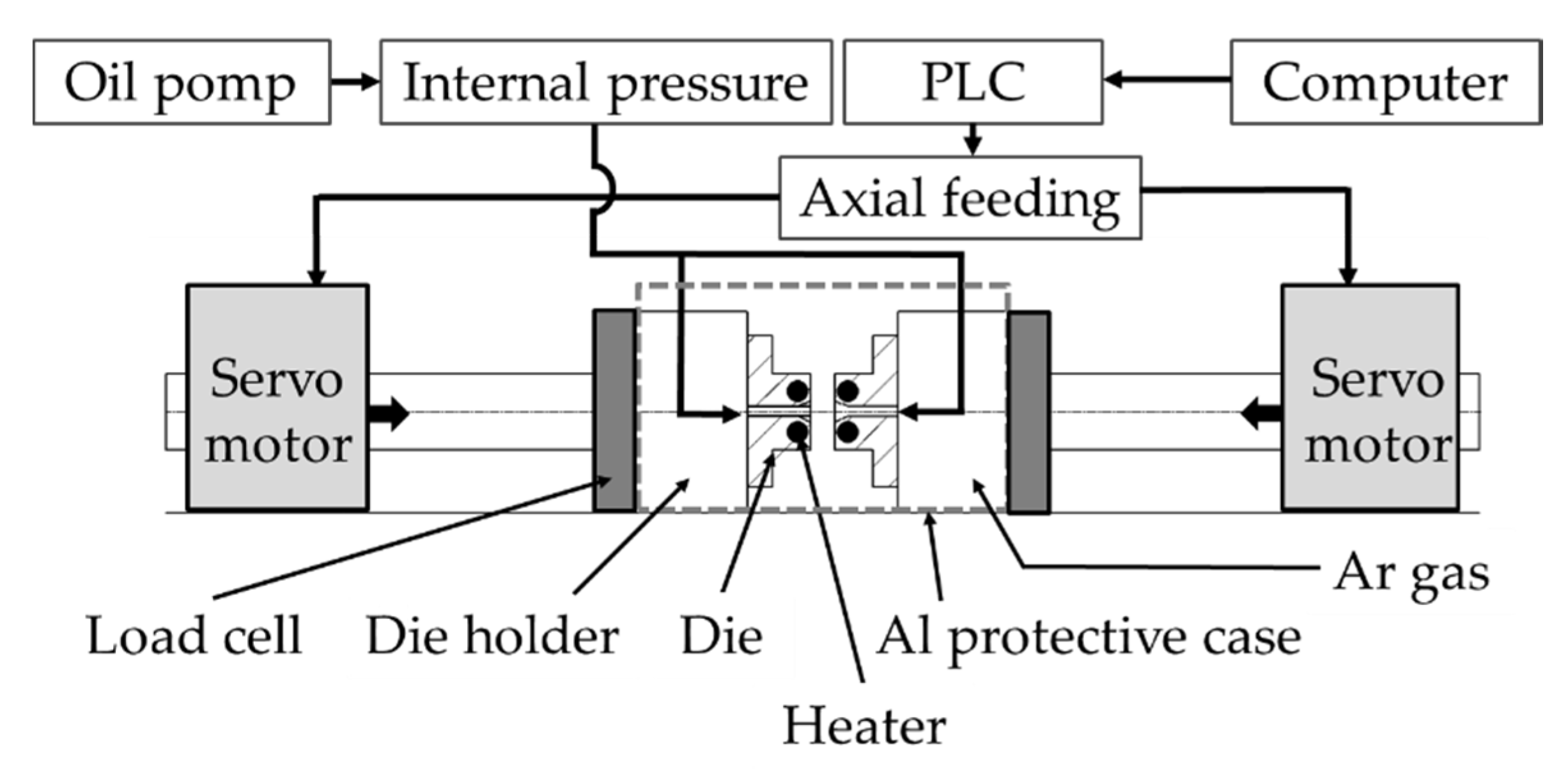
Figure 1 shows the appearance of the THF machine, and Figure 2 shows a schematic of the THF system used for the experiment in this study. The machine consisted of an oil pump, servo-motors, load cells, cartridge heaters (250 W) and a heater controller. The pump loaded the internal oil pressure, and the motors applied the axial feeding for both tube ends. The processing was carried out at 250 °C. The heaters could heat the tube to 250 °C in approximately 140 s. The heat resistance of the oil was 350 °C. During the heating, the machine was covered by a case made of aluminum, and the case was filled by Ar gas to avoid fire.
Figure 3a shows the oil sealing mechanism. The oil was sealed by two O-rings. The deformation of each tube end inside the oil pool was restrained by a restraining ring made of steel to avoid expansion of the tube in areas other than the die cavity. Figure 3b shows the loading mechanism of the axial feeding and the internal pressure. The axial feeding was carried out by closing the die, in which process the distance between the left and the right die was changed. Therefore, the optional axial feeding amount was set as the distance between the left and the right die. These mechanisms could resolve problems, such as the preparation of a high-precision axial compressive punch and oil-sealing part, which were required in using THF with small tubes.

2.2. Material Characteristic and Results of the Tensile Test and Bursting Test

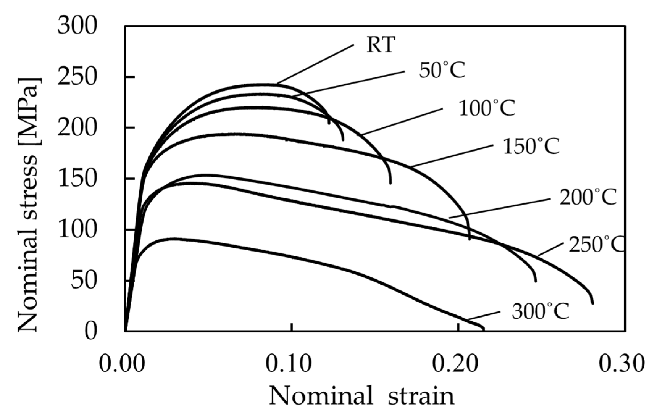
The mechanical properties of ZM21 magnesium alloy were obtained by tensile and bursting tests. Each specimen undergoing these tests were annealed at 300 °C for 24 h. First, to understand the rough tensile characteristics of ZM21, a tensile test using ZM21 magnesium alloy rods was carried out. Table 1 shows the chemical composition of the ZM21 rods used for the tensile test. The rods, with an outer diameter of 6.0 mm, were manufactured by hot extrusion. The tensile speed was 0.6 mm/min, and the test temperature in the warm region was raised by increments of 50 °C. Figure 4 shows the nominal stress–nominal strain diagram of the specimens, obtained from the tensile test. As a result, the decrease of the deformation resistance and the improvement of the ductility were confirmed at elevated temperatures. The ductility of the ZM21 rod at 250 °C is 220% higher than the test result at RT. It is considered that using warm THF with ZM21 magnesium alloy at 250 °C is appropriate, because of its excellent ductility and low resistance to deformation.
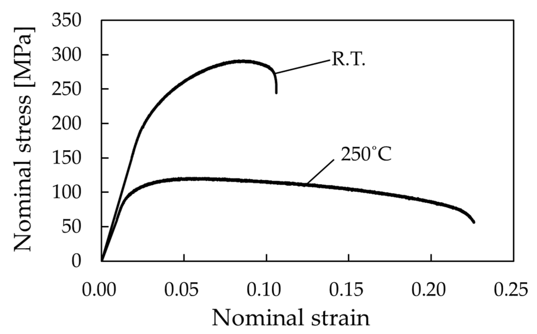
Then, the material characteristic of the small-diameter ZM21 tube, which was used for THF, was evaluated by the tensile test at RT and 250 °C. The tube material manufactured by hot drawing [16] has a similar chemical composition to the ZM21 rod, as shown in Table 1. The tube has a 2.0 mm outer diameter and 0.2 mm wall thickness. The tubular test specimen was chucked between the upper and lower chucks, with a distance between each chuck of approximately 10 mm, which is the same as the gauge length. The tensile speed was set to 0.6 mm/min. Figure 5 shows the nominal stress–nominal strain diagram of the ZM21 tube. The ductility of the ZM21 tube at 250 °C is 210% higher than the test result at RT. Comparing the tensile test results, shown in Figure 4, with the test results for ZM21 rods, shown in Figure 5, correlations are observed between the tube and the rod materials in relation to changes of the deformation resistance and the ductility.
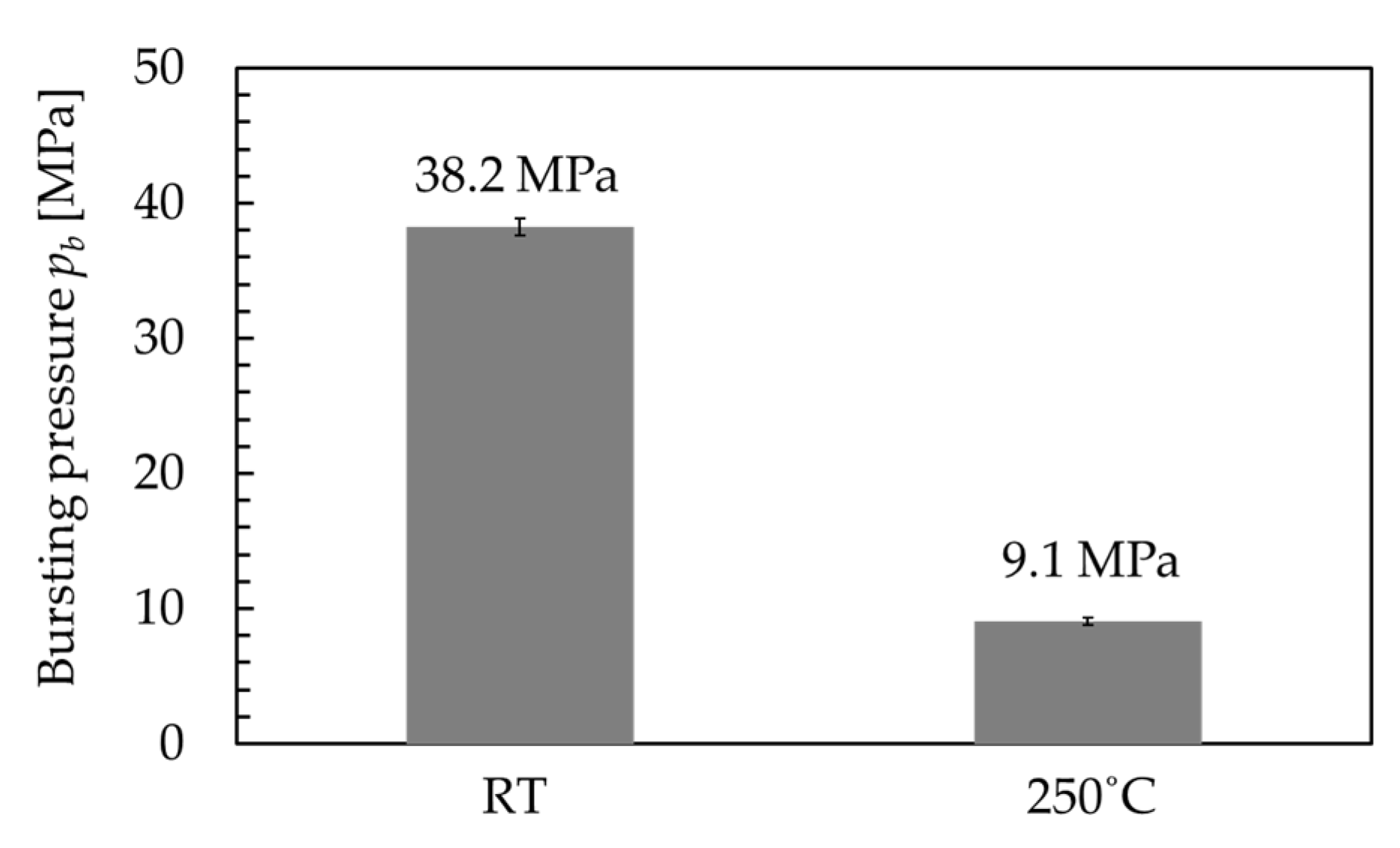
Moreover, the bursting pressure pb of the ZM21 tube was measured by the bursting test at RT and 250 °C, in order to define the fracture limit of the tube in THF. The internal pressure was loaded linearly by 1.0 MPa/s, until the tube burst. Figure 6 shows the result of the test. The bursting limit at 250 °C is 23% of the limit at RT.
Furthermore, to evaluate the expansion characteristics of the tube in the THF process, warm free bulge forming was conducted at RT, 150 °C, 250 °C and 300 °C [14]. The tubes used had a 2.0 mm outer diameter and 0.15 mm wall thickness. Figure 7 shows a comparison of the expansion characteristics of the hydroformed tubes. In this process, the internal pressure was set at 20% lower than the bursting pressure pb of the initial tube. From this experiment, it was confirmed that the warm-hydroformed ZM21 tube at 250 °C (Figure 7b) could be deformed sufficiently, and expanded most in these temperature conditions. The expanded tube had a 3.52 mm outer diameter. Thus, under this temperature condition, the highest expanding height could be obtained.

2.3. Experimental Methods

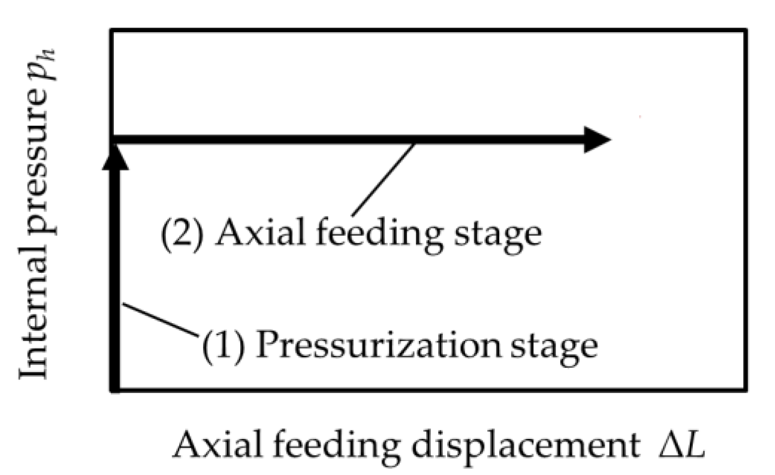
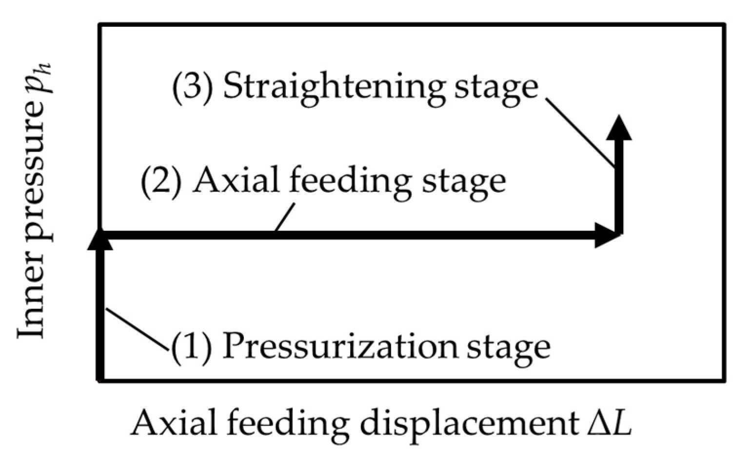
Warm THF was conducted on the small-diameter ZM21 tube with a 2.0 mm outer diameter and 0.2 mm wall thickness under an elevated temperature condition (250 °C). Silicone oil was used as the hydraulic pressure medium, and molybdenum disulfide (MoS2) paste was employed to provide lubrication between the tube and the die. Figure 8 shows the loading path of the internal pressure ph and the axial feeding displacement ΔL adopted in the experiment. In the loading path, Stage (1) is the hydraulic pressure stage. The internal oil pressure is loaded on the predetermined internal pressure ph. The pressure is maintained after the pressure medium is filled, and the air in the tube is vented. The value of ph was defined based on α. It is defined by a percentage of the loaded internal pressure ph to the bursting pressure pb. After that, in Stage (2), axial feeding is carried out to deform the tube, which produces the axial feeding displacement ΔL = a maximum of 1.5 mm, while maintaining the internal pressure ph. In Stage (2), the axial feeding is applied at a speed of 0.025 mm/s.
Figure 9 shows the die used for the warm THF experiment. The deformation characteristics of the tubes, which are deformed in the taper-cavity die (Figure 9a) and the cylinder-cavity die (Figure 9b), were evaluated. The divided asymmetrical dies with A-side and B-side parts, as shown in the figures, were employed. Each side has a different cavity: the A-side has a straight cavity, without bulging, and the B-side has a taper- or a cylinder-cavity. The taper- and the cylinder-cavity have an expansion ratio that is 1.5 times the maximum, in comparison with the initial outer diameter of the ZM21 tube. Before processing, every tube was annealed at 300 °C for 24 h.

2.4. FEM Model and FE Analysis Conditions

The warm THF process was analyzed by the FE method (FEM) to evaluate the deformation behavior of the tube in the processing. The FEM code used was the dynamic explicit LS-DYNA 3D (ver. 19. 2) (ANSYS Inc. Canonsburg, PA, USA). The FE models were constructed for one-quarter of the entire part, considering the geometrical symmetry of the THF model, as shown in Figure 10. Figure 10a is an FEM model that includes a taper-cavity die, and Figure 10b includes a cylinder-cavity die. In these models, the tube has a length of 17 mm, an outer diameter of 2.0 mm and a wall thickness of 0.2 mm. Solid elements were used for the tube and the dies. Rigid bodies were employed for the die parts. The isotropic elastoplastic material was applied for the material model of the ZM21 tube. The model was meshed, and the element was a ten-node element. The tube has 6 elements in the thickness direction. The minimum element size of the tube was 33 µm × 33 µm × 39 µm. The number of total elements for the tube blank and the dies are 192,000 and 1666, respectively.
The mechanical properties of the ZM21 magnesium alloy tube at 250 °C used in the simulations are shown in Table 2. The material characteristics of the tube were determined using a true stress–true strain diagram, which was created based on the nominal stress–nominal strain diagram shown in Figure 5. The stress–strain data were inputted as the values approximated by a multiline approximation approach. In the simulation, the Coulomb friction model was used, and the friction coefficient was 0.1. The kinetic friction coefficient was defined as the same value as static. In the simulation, the internal pressure and the axial feeding were linearly loaded along the loading path shown in Figure 8.
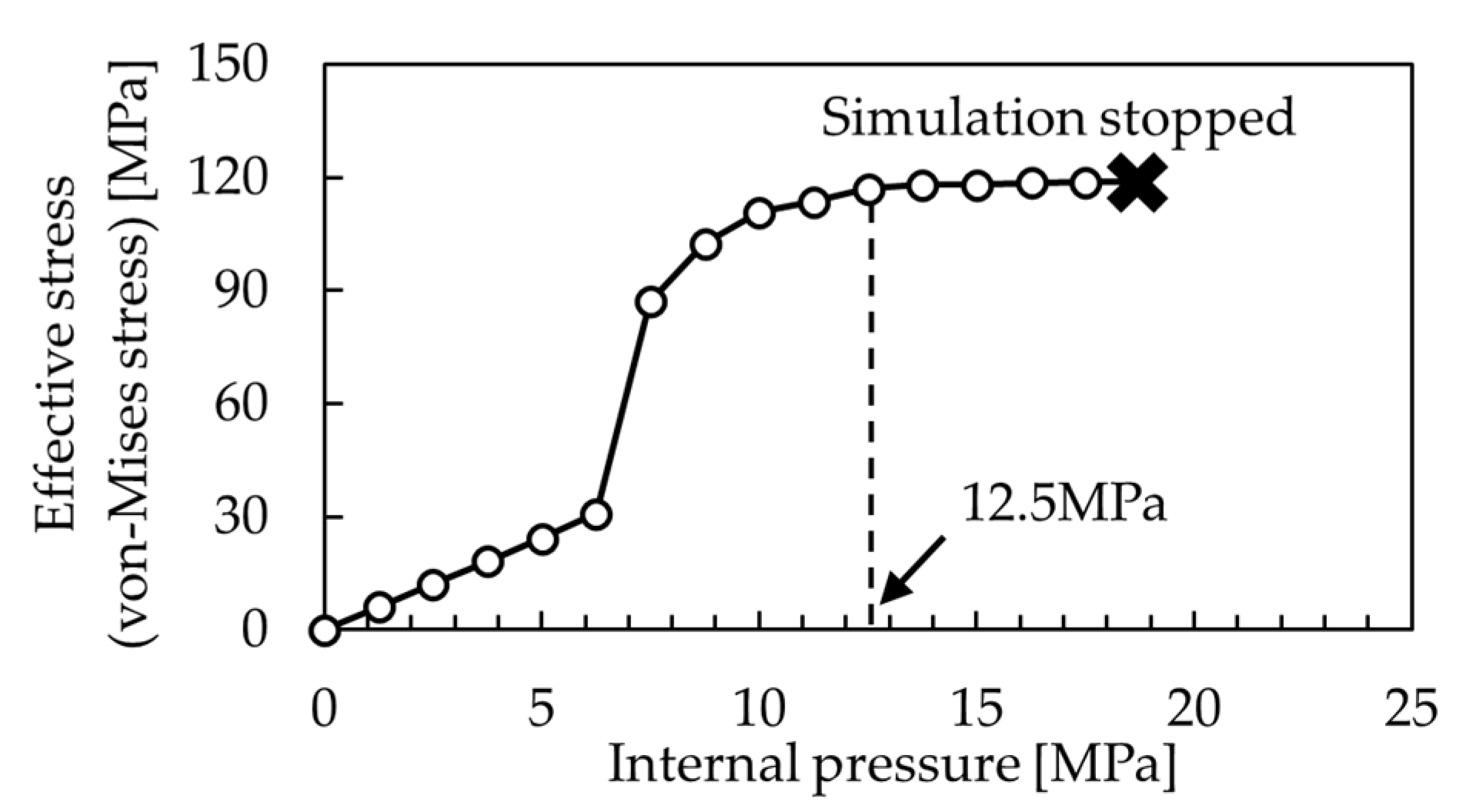
To define the internal pressure conditions in the simulation, the bursting pressure was calculated by the bursting test in FEM. In this test, the internal pressure ph was loaded linearly, without loading of the axial feeding. Figure 11 shows the maximum equivalent von-Mises stress of the tube obtained from the test. The tube reached around the maximum value of the stress at ph = 12.5 MPa. After that, the simulation stopped due to the occurrence of a negative volume of the elements in the tube. Therefore, it is considered that the bursting pressure pb of the tube in FEM is 12.5 MPa.

3. Results and Discussion

3.1. Fracture and Buckling Limits of the Tube in Relation to the Loaded Internal Pressure

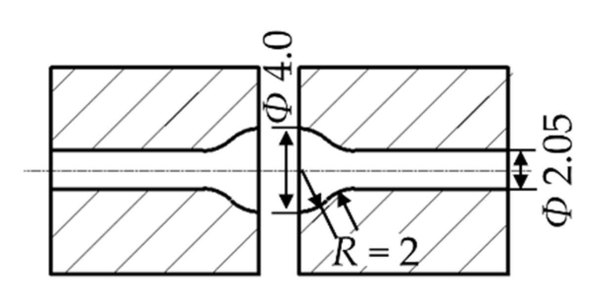
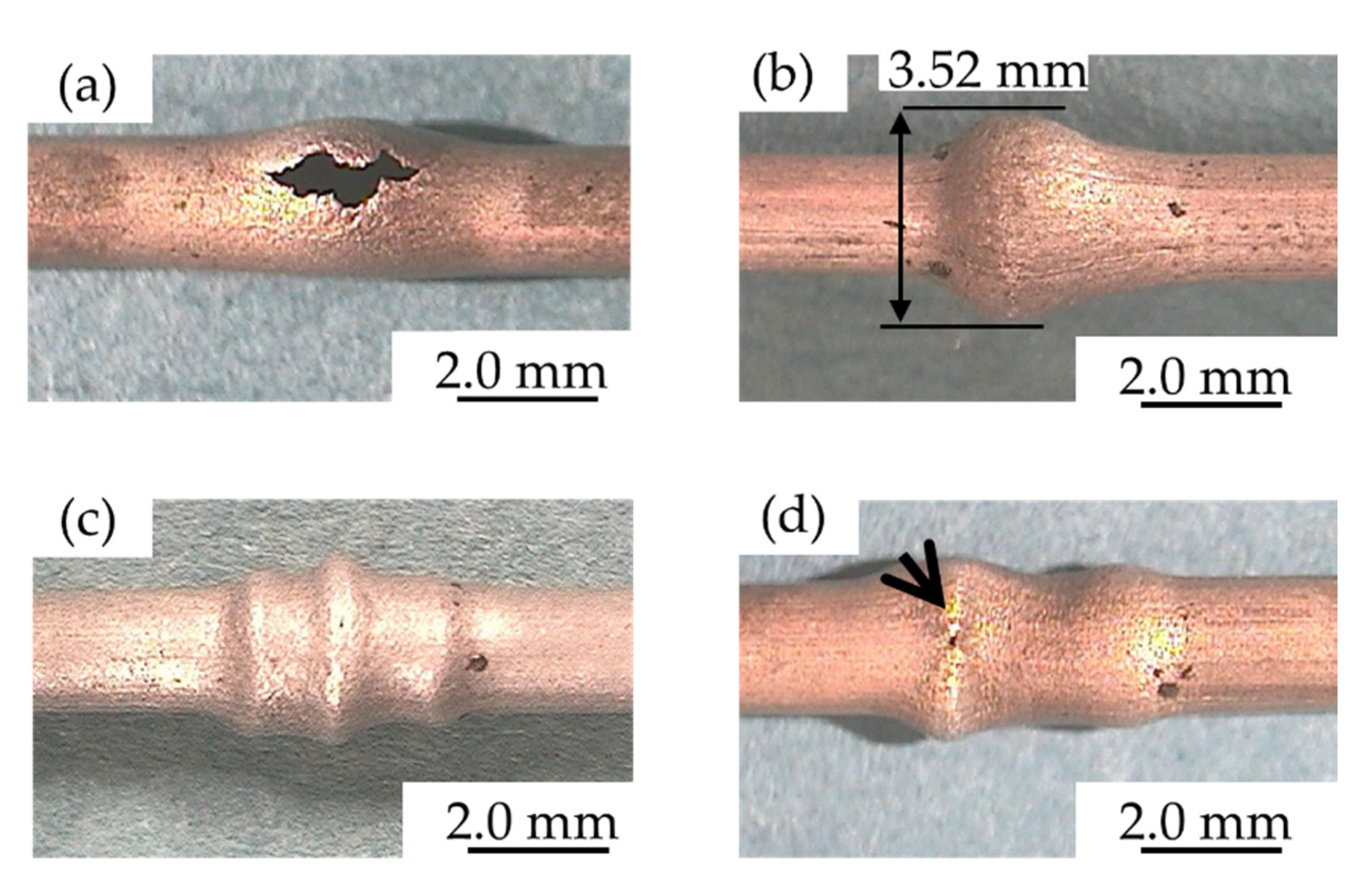
To determine the value of the internal pressure that is loaded during the axial feeding in Stage (2) shown in Figure 8, the fracture and the buckling limits of the small-diameter ZM21 tube were evaluated by warm free bulge forming at 250 °C. The die used for this evaluation is shown in Figure 12. The employed internal pressure conditions α were 90%, 80%, 70% and 50%, and the axial feeding was performed at ΔL = 1.5 mm. Figure 13 shows the hydroformed tubes obtained under each condition. When the loaded pressure was high (Figure 13a), the tube fractured immediately after the axial feeding was applied (ΔL = 0.27 mm), and the tube could not be expanded. On the other hand, when the loaded pressure was low (Figure 13c), wrinkles appeared on the tube. Additionally, the tube was fractured by severe folding deformation when the maintained internal pressure α was 50%, as shown in Figure 13d. Therefore, it is considered that the buckling limit of the tube α = 50%, and the fracture limit α = 90%. However, the tube successfully expanded when α was 80%. Figure 13b shows the successfully hydroformed tube, without wrinkles, folds or fractures. The outer diameter of the hydroformed tube was 3.23 mm, in this case.

3.2. Influence of the Axial Feeding Direction on the Deformation Characteristic in Warm Tube Hydroforming

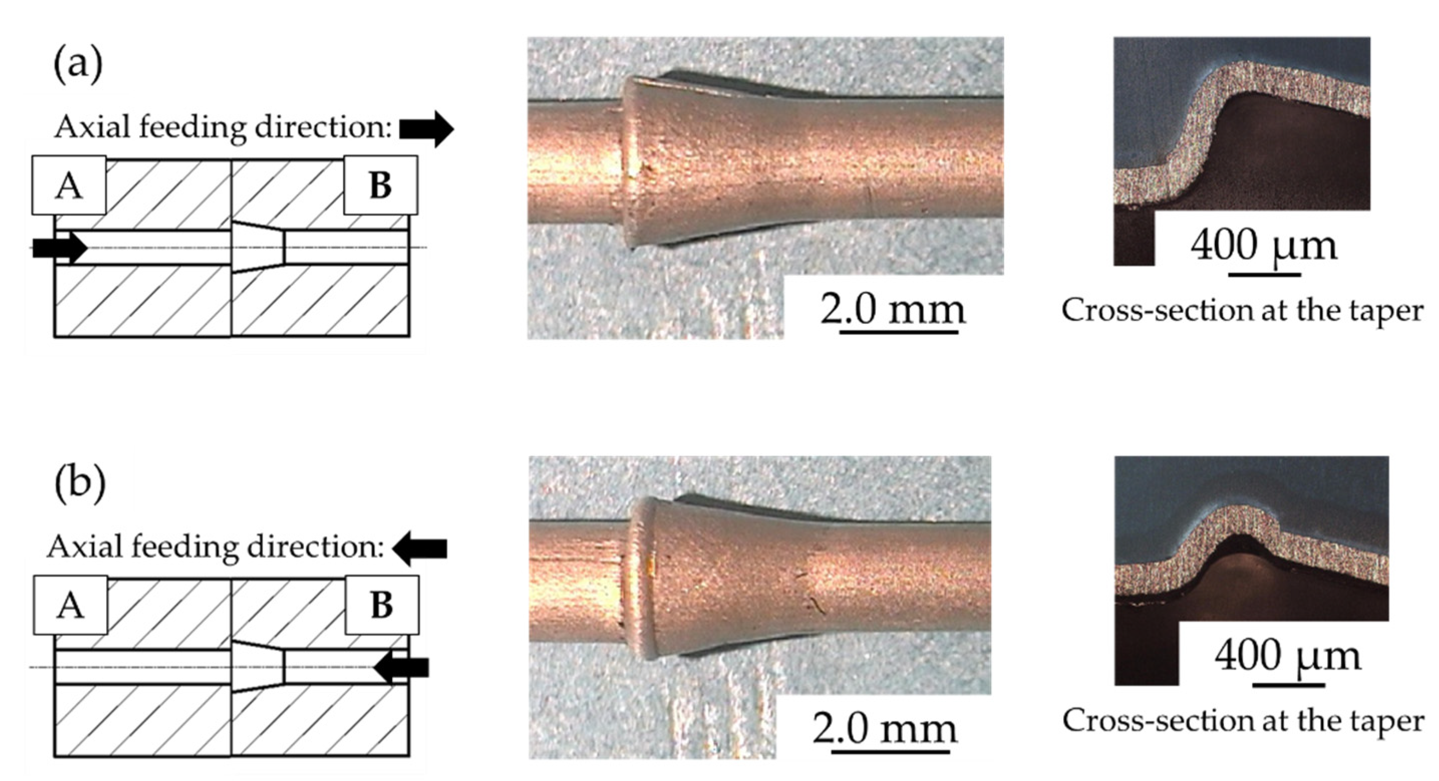
Since asymmetrical-shape dies would be used in this experiment, as mentioned in Section 2.3, it was considered that the difference in the axial feeding direction may influence the deformation of the tube [17]. Therefore, two conditions regarding the applied axial feeding direction for the tube were established, and the deformation characteristics of the small-diameter ZM21 tube was evaluated under these conditions at 250 °C. The conditions were named CASE A and CASE B. The axial feeding was applied only from the A-side in CASE A, and in CASE B, it was applied from the B-side only. In these conditions, the loaded axial feeding displacement ΔL was 1.5 mm, and the employed internal pressure condition α was 80%. Figure 14 shows the hydroformed tubes and cross-section of the deformed tube under both conditions using the taper-cavity die. The taper-shaped tube was successfully hydroformed into the die cavity shape in CASE A (Figure 14a). However, a wrinkle appeared on the surface of the tube in CASE B (Figure 14b). The cause of the occurrence of the wrinkle is considered to be the influence of the difference of the shoulder shape in the moved die on the deformation of the tube. When the axial feeding was applied to the die with a straight-cavity (A-side), the process led to an excellent formability of the tube.
Figure 15 shows the axial compressive force measured by the load cell mounted on each die end during the processes. In these results, the increase of the axial compressive force from around ΔL = 0.5 to 1.0 mm was caused by a rise in the hardness of the tube material, which was affected by the occurrence of the twin boundaries during the process [15,18]. Additionally, it is considered that the increase from around ΔL = 1.2 to 1.5 mm was caused by the bending deformation added to the expanding deformation in filling the tube material in the die corner. By comparing the measured axial compressive force in CASE A and CASE B, a difference was found in the value of the measured axial compressive force. The incline of changes showed that it clearly differed. Therefore, it seems that the difference between the deformation behavior of the tubes was caused at around ΔL = 1.0 mm, and a wrinkle appears at that time.
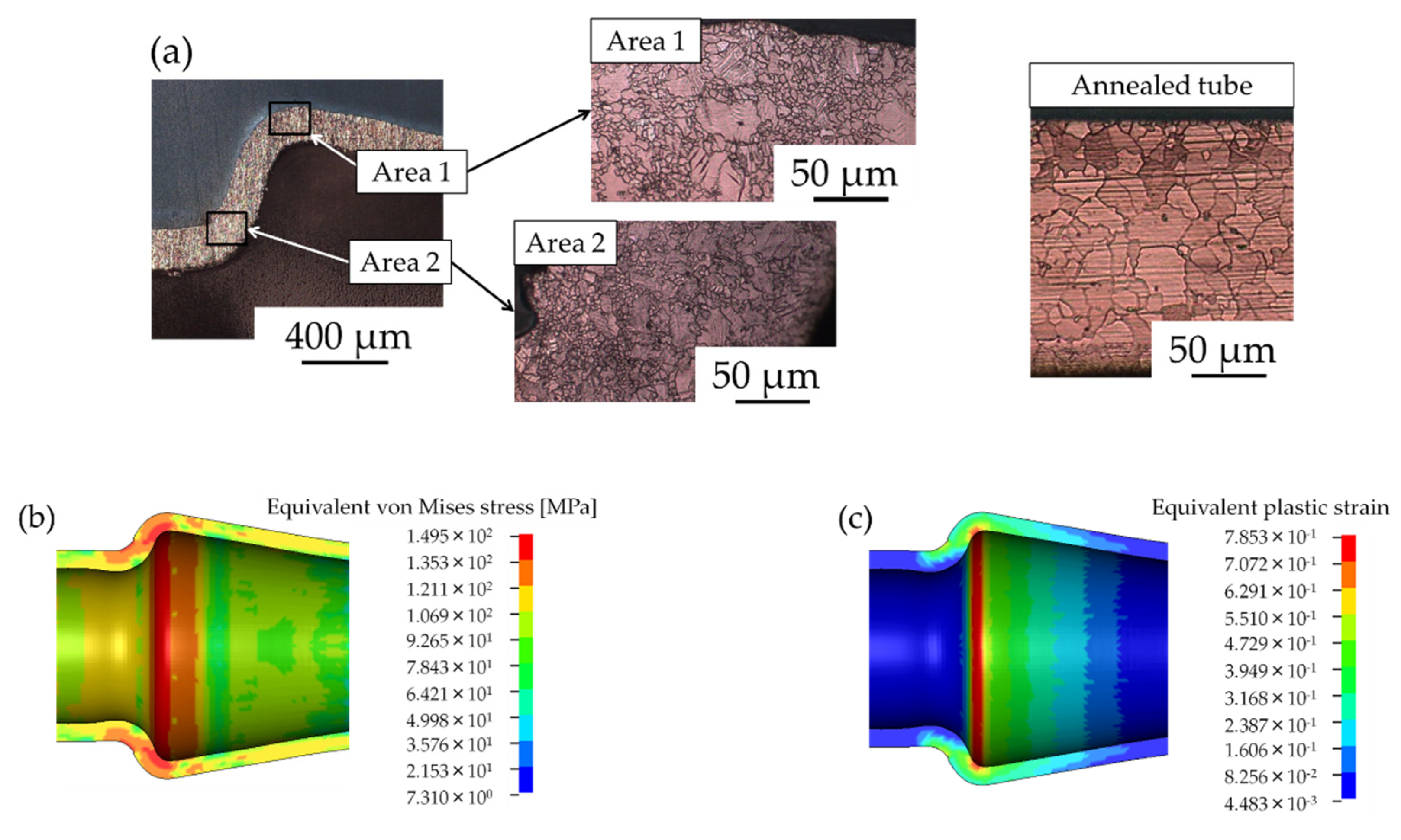
In addition, Figure 16a shows the microstructure in the taper-shaped tube obtained in the CASE A condition. Grain with twin boundaries and grain that is finer than the grain in the annealed tube were confirmed in the taper-shaped tube. Figure 16b shows the equivalent von-Mises stress, and Figure 16c shows the equivalent plastic strain in the deformed area of the tube. These plots show that higher compressive stresses and strain appeared conspicuously on the inside of the bended part of the hydroformed tube. There is a correlation between the area where the grain with twin boundaries and the refined grain were observed and that where the higher compressive stresses and strain appeared. It is considered that the deformed tube has advantages, such as a high strength and high-stress corrosion resistance, because of the refinement of the grain. However, their occurrence behavior during the process is yet to be observed and noted in detail. More specific observations of the changes of the microstructure in the tube during the deformation is necessary in evaluating the refinement behavior of the grain in the hydroformed tube.

3.3. Forming Defects

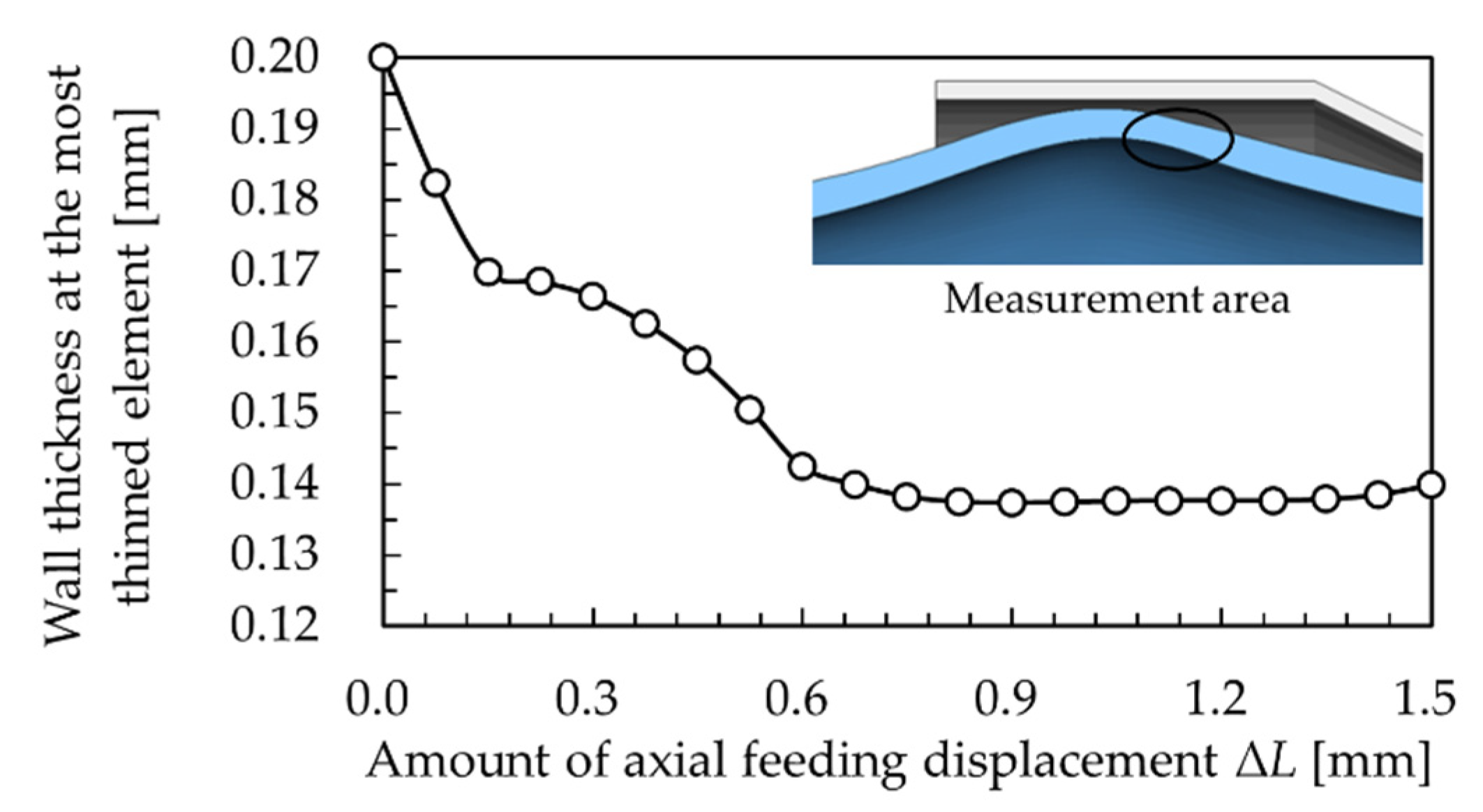
When the cylinder-cavity die was employed, warm THF was impossible under both axial feeding conditions, because the tube was fractured during the processing. Figure 17 shows the deformation behavior of the tube, which was deformed in the cylinder-cavity die obtained by FEM. In addition, Figure 18 shows the thinning behavior of the wall of the tube, in the area where the maximum reduction of the wall thickness was observed in FEM. As shown in Figure 17, the tube appeared to have been deformed successfully at first glance. However, it is clear that a severe decrease of the thickness occurred at ΔL = 0.525 mm. The maximum thickness strain in that area was −31.5% at ΔL = 0.9 mm, and the wall thickness of the tube was decreased from 0.2 mm to 0.137 mm. It is considered that the tube fractured during the axial feeding, due to the severe thinning deformation of the wall in the experiment. Therefore, the suppression of the thinning of the wall is necessary to avoid fracture when the cylinder-cavity die is employed for warm THF.
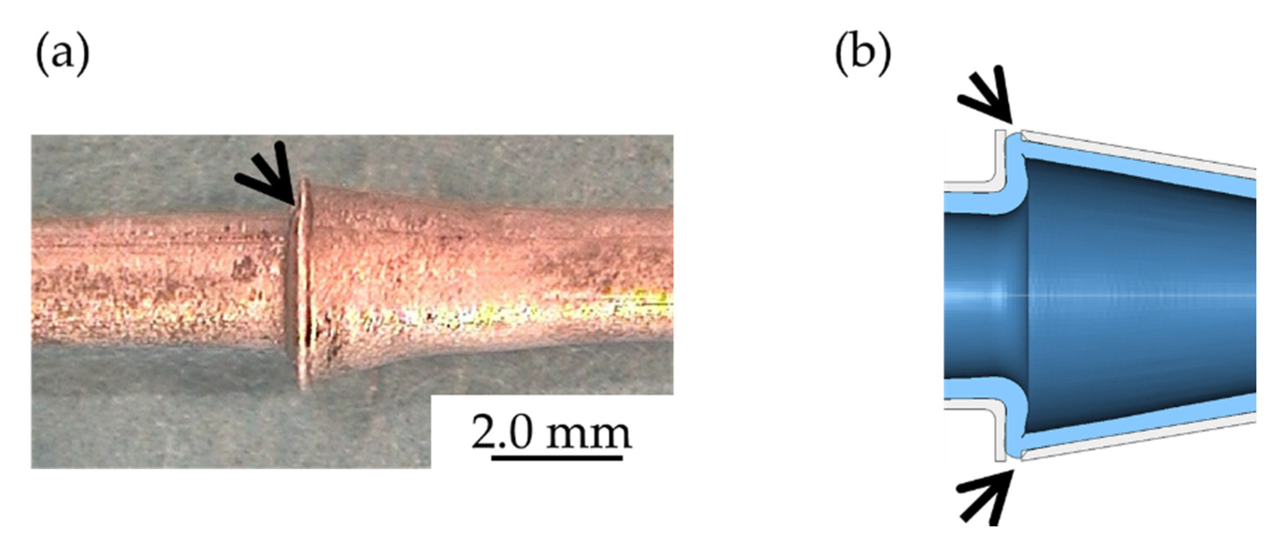
On the other hand, Figure 19 shows a deformation defect obtained when warm THF was employed with the taper-shape die. This defect was caused because the closing die pinched the tube, which expanded to an extreme extent during the axial feeding. Excessive expansion of the tube is caused by uncontrollable fluctuation of the internal pressure during the processing. In the experiment, the internal pressure fluctuates within a maximum error of approximately 5%, because of the change of the tube volume with the expansion, the thinning of the wall, and a leak of the pressure medium.

3.4. Influence of Deference in the Loading Path on the Deformation Characteristics in Warm Tube Hydrofoming

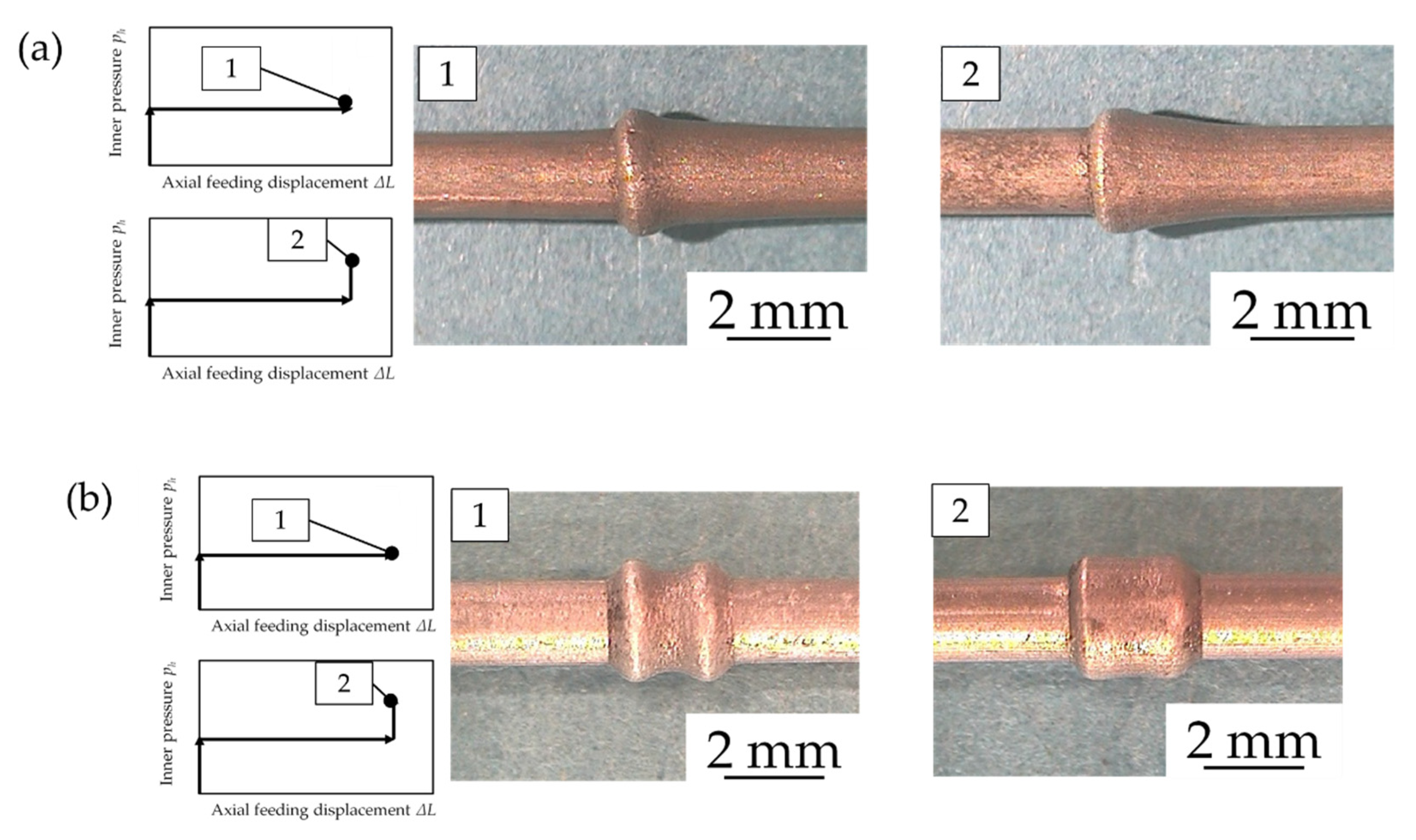
Figure 20 shows the modified loading path. To avoid forming defects, as mentioned in Section 3.3, the internal pressure ph at Path (2) was maintained with a lower value, which can suppress the occurrence of forming defects. In this experiment, the internal pressure was loaded, and it was α = 60% in Stage (1) and (2). In Stage (2), the axial feeding was applied while maintaining the internal pressure. The occurrence of wrinkling is allowed in this stage. After that, the straightening stage was installed, as Stage (3) in the loading path, to expand the wrinkled tube. The internal pressure was raised from α = 60% to 80% in the straightening stage. The experiments were carried out at 250 °C, and the axial feeding condition used was CASE A, with ΔL = 1.5 mm. The hydroformed samples were observed in Stage (2) and (3).
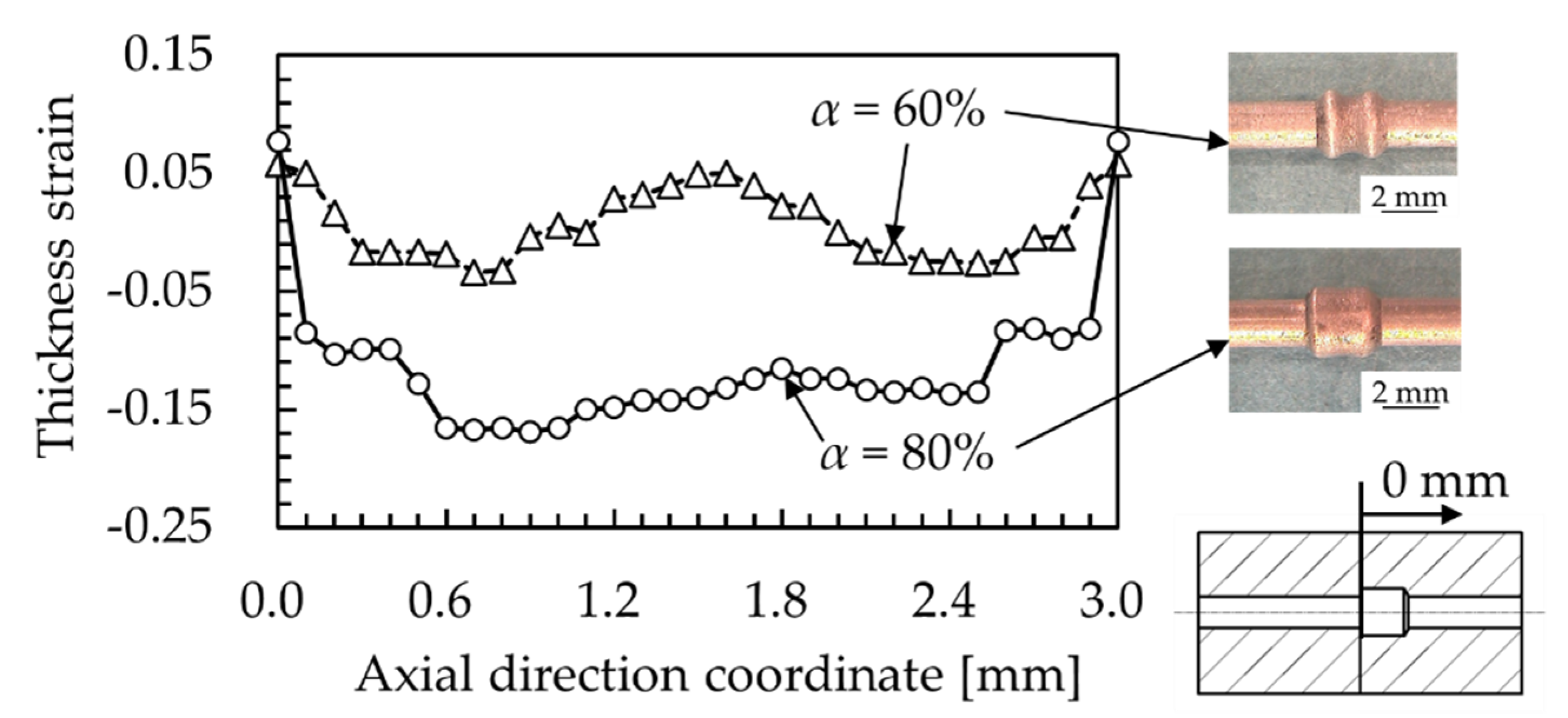
Figure 21 shows the hydroformed small-diameter ZM21 tubes, which were obtained by warm THF using the modified loading path. Every picture of the hydroformed tube shown in the figure was deformed from other materials. The experiments were not carried out using the same tube. The tubes with wrinkles were expanded into a taper shape (Figure 21a) and cylinder shape (Figure 21b) successfully in Stage (3). Figure 22 shows the deformation behavior of the tube during warm THF using the cylinder-cavity die in FEM. There is no area where the wall of the tube is very thin. Additionally, Figure 23 shows the thickness strain of the tube deformed using the cylinder-cavity die in the experiment. The thinning amount of the wall of the wrinkled tube was suppressed, compared with the tube that was deformed using the initial loading path shown in Figure 8. The maximum thickness strain was −2.5%. Moreover, the maximum thickness strain of the tube at the end of Stage (3) was −16.8%. From these results, it is considered that the warm THF using the cylinder-cavity die was successful because of the suppression of the thinning of the wall. It is clear that the value of the loaded internal pressure during axial feeding is an important factor that influences the deformation of the tube.
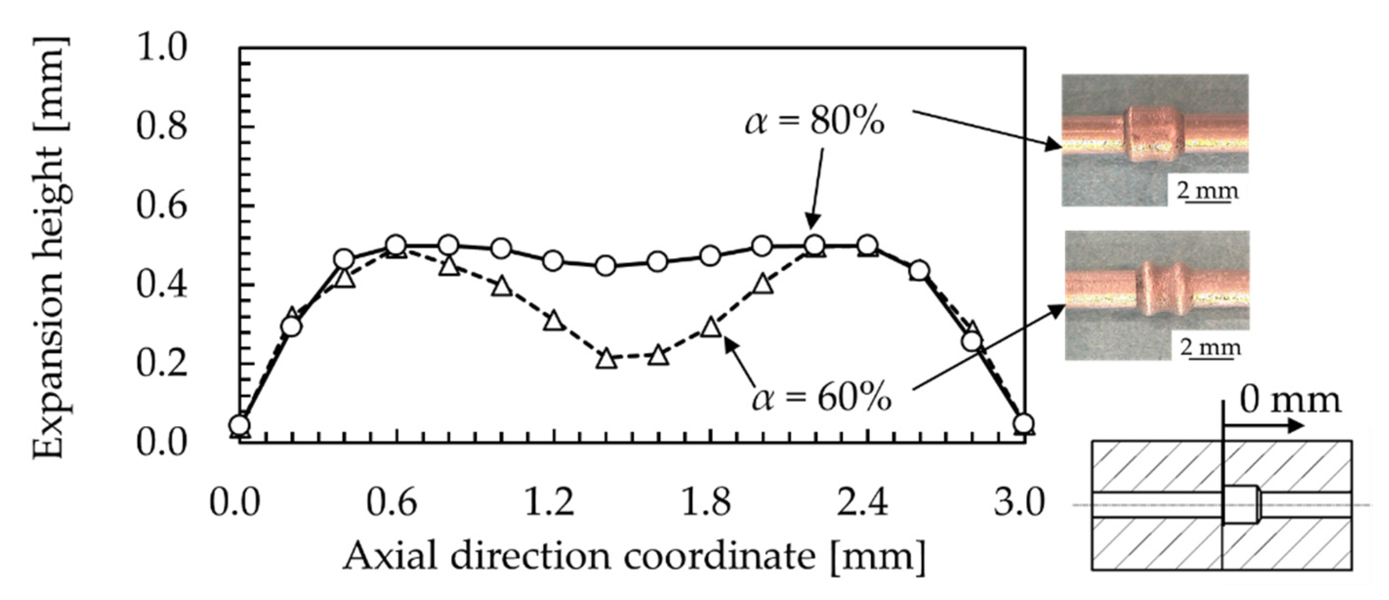
On the other hand, the wall thickness of the hydroformed tubes was not uniform. Figure 24 shows the expansion distribution of the hydroformed tubes. Remarkably, the expansion of the tube occurs in the valley of the wrinkle. Compared with the deformed tube shape, the position of the notably thickened area was the shoulder and the valley part between the left wrinkle and right wrinkle in Stage (2), as shown in Figure 23. After the straightening (Stage (3)), the thinning remarkably proceeded in the valley. This thinning is caused by a local expansion in the valley of the wrinkles. The deformation of the tube is constrained due to the top of the wrinkles touching the die cavity at the end of Stage (2). Therefore, the tube is expanded in the valley of the wrinkles only in Stage (3), and this area shows severe thinning deformation of the wall.

3.5. Forming Limit

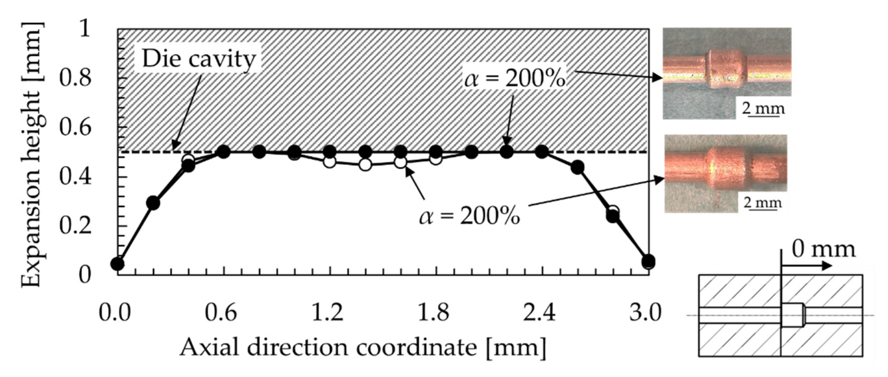
The fracture limit of the small-diameter ZM21 tube in Stage (3) in the modified loading path was investigated in the experiment. The cylinder-cavity die was employed for this evaluation. In Stage (3), the internal pressure was loaded at a speed of 1.0 MPa/s, until fracturing. Figure 25 shows the deformed tubes in Stage (3). The wrinkled tubes could withstand a higher internal pressure than the bursting pressure pb of the initial tube obtained from the bursting test. The warm THF was successful when α = 200%, as shown in Figure 24. However, when the loaded pressure α was 200% or more, the tubes tended to fracture, as shown in Figure 25b,c. Bursting of the tube under the higher-pressure region occurred in the area around the right-angle die corner. It is considered that the tubes could withstand a higher pressure than the bursting pressure, owing to the die cavity and the thickening of the wall in the expanded valley of wrinkle constraining the expansion of the tube, as mentioned in Section 3.4.
In addition, the expansion distribution of the hydroformed tube with the loaded pressure condition α = 200% in Stage (3) is shown in Figure 26. The results of the warm THF, without the straightening (α = 60%) and with the straightening (α = 80%), are shown in that figure for comparison. The tube expanded sufficiently from the wrinkled to the cylinder-shape when α = 200%. Conversely, the expansion of the tube, which was straightened with raised pressure α = 80%, was incomplete, compared with the hydroformed tube with α = 200%. The cause of the insufficient expansion when α was 80% in the straightening stage is considered to be the high strength of the tube material, owing to grain refinement, as mentioned in Section 3.2. Figure 27 shows the microstructure of the tube that was wrinkled in Stage (2). At the top of the wrinkle, there were approximately 20 fine-grained layers in the wall thickness direction, as shown in Figure 27b, and the average grain size was approximately 9.3 µm (Figure 27a). On the other hand, the grain size in the non-deformed area was 21.5 μm. Therefore, warm THF of the tube, from the wrinkle to the die cavity shape, requires the loading of a higher internal pressure to straighten the wrinkle.
Moreover, the forming limit for the die corner shape in the right-angle die corner was evaluated. Figure 28 shows the axial cross-sections of the taper-shaped tube (Figure 28a) and the cylinder-shaped tube (Figure 28b) under the conditions of ΔL = 1.5 mm and α = 80% in Stage (3). In each processing stage, filling to the die corner was insufficient. The obtained radii of the corner-shape R were 0.318 mm in Figure 28a and 0.384 mm in Figure 28b. From this result, it is considered that the forming limit of the tube in the die corner is approximately R = 0.3 to 0.4 mm. For the filling of the tube material to the sharper die corner, it seems that the material flow into the die is necessary. In this study, the axial feeding was carried out, without an axial compressive paunch. Thus, the tube material could barely flow into the die cavity. Additionally, there is a disagreement in the bending shape of the hydroformed tubes between the taper- and the cylinder-shaped tube. It is considered that this disagreement is caused by the difference in the ratio of the axial feeding displacement to the die-cavity volume between these dies. The cylinder-cavity die has a lager die cavity volume than the volume of the taper-cavity die. Therefore, optimization of the amount of the axial feeding displacement that is applied to the tube in relation to the die cavity volume is required.

4. Conclusions

In this study, warm THF at 250 °C for small-diameter ZM21 magnesium alloy tubes with an outer diameter of 2.0 mm and a wall thickness of 0.2 mm was examined by experimentation and FEM analysis. The influence of the loaded internal pressure and the axial compressive displacement on the deformation characteristics, the forming limit, and the forming defects of the tubes were examined and evaluated. The results obtained in this study are summarized below.
  • The fracture and buckling limit of the tube during warm THF were clarified. When the employed loading internal pressure condition α, which is a percentage of the internal pressure ph to the bursting pressure pb of the initial tube, was 90%, hydroforming of the ZM21 tube was impossible due to a fracture of the material during the axial feeding. On the other hand, warm THF, which was employed under the condition of α = 50%, caused buckling of the tube, and the tube was fractured by a severe folding deformation.
  • When the loaded internal pressure condition α was 70%, the tube with wrinkles was obtained. The warm THF under the condition of α = 80% was successful, without fracture and wrinkles.
  • The effect of the axial feeding direction on the deformation characteristics of the ZM21 tube was confirmed. The difference in the deformation behavior of the tube occurred around the axial feeding displacement ΔL = 1.0 mm. Additionally, the taper-shaped tube that was hydroformed successfully had grain with twin boundaries and refined grain in the bended and the expanded areas.
  • The observed forming defects of the ZM21 tube were fracturing of the tube during the axial feeding in warm THF using the cylinder-cavity die and pinching of the material in the section between the left and right die caused by die closing and an excessive expansion of the tube. The fracture of the tube could be caused by the severe thinning deformation of the wall with a maximum thickness strain of −31.5%. It is confirmed that a lower loaded internal pressure during the axial feeding stage is required to avoid the occurrence of these defects.
  • Warm THF for the tube using the cylinder-cavity die was successful, with the modification of the loading path. The thinning that appears during the axial feeding was suppressed by the loaded lower internal pressure. The hydroformed tube obtained by warm THF using the modified loading path had a maximum thickness strain of −2.5% after the axial feeding stage. The tube with the wrinkles could be expanded successfully into the taper and the cylinder shapes by increasing the pressure in the straightening stage.
  • The fracture limit of the tube during warm THF in Stage (3) was α = 200%. In addition, when the loaded pressure α was 200% or more, the tubes tended to fracture at the corner in the die cavity. The improvement of the fracture limit of the tube in Stage (3), compared with that of the initial tube, is caused by the thickening of the wall, which occurs in Stage (2), and the high strength due to the finer grain.
  • The radius of the bended area in the taper- and cylinder-shaped tube were measured. It is considered that the forming limit of the tube with the die-corner shape was around R = 0.3 to 4.0 mm.

Author Contributions

Conceptualization, S.Y. and H.Y.; Methodology, H.Y.; Resources, T.F.; Material provision, T.F.; Experimental work, H.Y. and T.M.; Numerical analysis, H.Y. and T.M.; Data curation, H.Y.; Writing—original draft preparation, H.Y.; Supervision, S.Y., R.Y. and Y.I.; Project administration, S.Y.; Funding acquisition, S.Y. All authors have read and agreed to the published version of the manuscript.

Funding

This work was supported by The Die and Mold Technology Promotion Foundation.

Conflicts of Interest

The authors declare no conflict of interest.

References

  1. Yamamoto, R. Biomedical application of magnesium alloys. J. Jpn. Inst. Light Metals 2008, 58, 570–576. [Google Scholar] [CrossRef]
  2. Bommala, V.K.; Krishana, M.G.; Rao, C.T. Magnesium matrix composites for biomedical applications: A review. J. Magnes. Alloy. 2019, 7, 72–79. [Google Scholar] [CrossRef]
  3. Yoshihara, S.; Furushima, T. Development and applications of magnesium alloy micro tubes: Efforts on development bio-absorbable material. J. Jpn. Soc. Technol. Plast. 2016, 57, 1028–1033. [Google Scholar] [CrossRef]
  4. Choudhary, L.; Raman, R.K.S.; Hofstetter, J.; Uggowitzer, P.J. In-vitro characterization of stress corrosion cracking of aluminium-free magnesium alloys for temporary bio-implant applications. Mater. Sci. Eng. C 2014, 42, 629–636. [Google Scholar] [CrossRef] [PubMed]
  5. Manabe, K.; Fuchizawa, S. Tube forming technology: Toward the highest card for weight savings. J. Jpn. Soc. Technol. Plast. 2011, 52, 33–41. [Google Scholar] [CrossRef]
  6. MacDonald, B.J. Finite element simulation of hydroforming processes—A review and future directions. J. Jpn. Soc. Technol. Plast. 2012, 53, 176–182. [Google Scholar] [CrossRef]
  7. Cahn, L.C. Finite-element damage analysis for failure prediction of warm hydroforming tubular magnesium alloy sheets. J. Miner. Metals Mater. Soc. 2015, 67, 450–458. [Google Scholar]
  8. Manabe, K.; Fujita, K.; Tada, K. Experimental and numerical study on warm hydroforming for T-shape joint of AZ31 magnesium alloy. J. Chin. Soc. Mech. Eng. 2010, 31, 284–287. [Google Scholar]
  9. Manabe, K.; Morishima, T.; Ogawa, Y.; Tada, K.; Murai, T.; Nakagawa, H. Warm hydroforming process with non-uniform heating for AZ31 magnesium alloy tube. Mater. Sci. Forum 2010, 654, 739–742. [Google Scholar] [CrossRef]
  10. Liewald, M.; Pop, R. Magnesium tube hydroforming. Mater. Sci. Eng. Technol. 2008, 35, 343–348. [Google Scholar] [CrossRef]
  11. Geiger, M.; Kleiner, M.; Eckstein, R.; Tiesler, N.; Engel, U. Microforming. CIRP Ann. 2001, 50, 445–462. [Google Scholar] [CrossRef]
  12. Zhuang, W.; Wang, S.; Lin, J.; Hartl, C. Experimental and numerical investigation of localized thinning in hydroforming of micro-tubes. Eur. J. Mech. A Solids 2011, 31, 67–76. [Google Scholar] [CrossRef]
  13. Manabe, K. Micro forming processing of metal tubes. Jpn. Soc. Technol. Plast. 2019, 2, 8–13. [Google Scholar]
  14. Yasui, H.; Yoshihara, S.; Yamada, R.; Ito, Y. Deformation behavior on small-diameter ZM21 magnesium alloy tube in warm tube hydroforming. J. Jpn. Soc. Technol. Plast. 2019, 60, 346–351. [Google Scholar] [CrossRef]
  15. Yasui, H.; Yoshihara, S.; Mori, S.; Tada, K.; Manabe, K. Material deformation behavior in T-shape hydroforming of metal microtubes. Metals 2020, 10, 199. [Google Scholar] [CrossRef] [Green Version]
  16. Furushima, T.; Manabe, K. Fabrication of AZ31 magnesium alloy fine tubes by dieless drawing process. J. Jpn. Soc. Technol. Plast. 2010, 51, 990–992. [Google Scholar] [CrossRef] [Green Version]
  17. Miyagawa, T.; Yoshihara, S.; Yamada, R.; Ito, Y. Influence of process condition on forming for taper shape using small diameter A1100 aluminum tube in warm tube hydroforming. In Proceedings of the 137th Conference of Japan Institute of Light Metals, Koganei, Japan, 1–3 November 2019; pp. 93–94. [Google Scholar]
  18. Somekawa, H.; Singh, A.; Schuh, A.C. Effect of twin boundaries on indentation behavior of magnesium alloys. J. Alloy. Compd. 2016, 685, 1016–1023. [Google Scholar] [CrossRef]
Figure 1. Appearance of the small warm hydroforming system used for the experiments.
Metals 10 00674 g001
Figure 2. Schematic of the small warm hydroforming system.
Metals 10 00674 g002
Figure 3. Geometry diagram of the die for the warm tube hydroforming (THF): (a) sealing mechanism; (b) loading mechanisms of the axial feeding and internal oil pressure in the tube for the experiment.
Metals 10 00674 g003
Figure 4. Stress–strain curves of the ZM21 rod obtained from the tensile test result under various temperature conditions.
Metals 10 00674 g004
Figure 5. Stress–strain curves of the small-diameter ZM21 tube obtained from the tensile test result at R.T and 250 °C.
Metals 10 00674 g005
Figure 6. Bursting pressures of the small diameter ZM21 tube obtained from the bursting test result at R.T and 250 °C.
Metals 10 00674 g006
Figure 7. Expansion behavior of the tube at R.T and 250 °C: (a) fractured tube at R.T; (b) expanded tube at 250 °C.
Metals 10 00674 g007
Figure 8. Schematic of the loading path used in the experiment and finite element (FE) method (FEM).
Metals 10 00674 g008
Figure 9. Geometry and dimensions of the tube hydroforming dies used in this study: (a) a taper-cavity die; (b) a cylinder-cavity die.
Metals 10 00674 g009
Figure 10. Schematic of the finite element (FE) model: (a) FE model for the taper-shape warm THF; (b) FE model for the cylinder-shape warm THF.
Metals 10 00674 g010
Figure 11. Definition of the bursting pressures of the small-diameter ZM21 tube in FEM at 250 °C.
Metals 10 00674 g011
Figure 12. Schematic of the die cavity shape used for the evaluation of the fracture and bursting limit of the tube.
Metals 10 00674 g012
Figure 13. Deformation characteristics of the small ZM21 tube deformed under the various internal pressure conditions: (a) a fracture (α = 90%); (b) bulge without fractures or wrinkles (α = 80%); (c) a wrinkle (α = 70%); (d) a wrinkle and folding (α = 50%).
Metals 10 00674 g013
Figure 14. Effect of the axial feeding direction on the deformation characteristics of the small ZM21 tube: (a) taper-shaped tube; (b) wrinkle.
Metals 10 00674 g014
Figure 15. Effect of the axial feeding direction on the axial compressive force during the process: (a) no wrinkle; (b) wrinkle.
Metals 10 00674 g015
Figure 16. Microstructure at different positions of the taper-shaped tube and the FEM results of the taper-shape forming: (a) Microstructure of the taper-shaped tube; (b) distribution of the equivalent von-Mises stress at the taper; (c) distribution of the equivalent plastic strain.
Metals 10 00674 g016
Figure 17. Deformation behavior of the small ZM21 tube in the cylinder-shape warm THF obtained by FEM.
Metals 10 00674 g017
Figure 18. Thinning behavior of the wall thickness in the cylinder-shape warm THF obtained by FEM.
Metals 10 00674 g018
Figure 19. Forming defect of the small ZM21 tube in the taper-shape warm THF: (a) experiment; (b) FEM.
Metals 10 00674 g019
Figure 20. Schematic of the modified loading path used for the experiment and FEM.
Metals 10 00674 g020
Figure 21. Deformation behavior of the small ZM21 tubes, which were deformed based on the modified loading path at 250 °C: (a) taper-shaped tube; (b) cylinder-shaped tube.
Metals 10 00674 g021
Figure 22. Deformation behavior of the small ZM21 tube in the cylinder-shape warm THF obtained by FEM at 250 °C using the modified loading path.
Metals 10 00674 g022
Figure 23. Thickness strain of the deformed tubes in the cylinder-shape warm THF at 250 °C.
Metals 10 00674 g023
Figure 24. Expansion distribution of the deformed tubes in the cylinder-shape warm THF at 250 °C.
Metals 10 00674 g024
Figure 25. Forming limit of the small ZM21 tube in the cylinder-shape warm THF at 250 °C: (a) no fracture (α = 200%); (b) fracture (α = 230%); (c) fracture (α = 250%).
Metals 10 00674 g025
Figure 26. Expansion distribution of the deformed tube, which was loaded with a higher internal pressure for the straightening of the wrinkle in the cylinder-shape warm THF at 250 °C.
Metals 10 00674 g026
Figure 27. Microstructure of the wrinkled tube obtained from the cylinder-shape warm THF in Stage (2) at 250 °C: (a) microstructure in the non-deformed area; (b) microstructure at the top of the wrinkle.
Metals 10 00674 g027
Figure 28. Radius shape of the corner of the deformed tubes: (a) taper-shaped tube; (b) cylinder-shaped tube.
Metals 10 00674 g028
Table 1. Composition of specimens for experiments (mass%).
MaterialAlZnMnSiFeCuNiMg
ZM210.0041.810.680.010.0280.0010.001Bal.
Table 2. Mechanical properties of the small-diameter ZM21 magnesium alloy tube used in FEM.
MaterialZM21 (250 °C)
Material modelElastoplastic body (Multilinear plasticity)
Mass density (kg/mm3)1800
Elastic modulus (GPa)8.20
Yield stress (MPa)90.76
Poisson’s ratio0.35