Article

Theoretical Model of Residual Stress and Warpage for Wire and Arc Additive Manufacturing Stiffened Panels

1
School of Mechanical Engineering and Automation, Fuzhou University, Fuzhou 350116, China
2
State Key Laboratory of Solidification Processing, Northwestern Polytechnical University, Xi’an 710072, China
*
Author to whom correspondence should be addressed.
Metals 2020, 10(5), 666; https://doi.org/10.3390/met10050666
Submission received: 19 April 2020 / Revised: 16 May 2020 / Accepted: 18 May 2020 / Published: 20 May 2020

Abstract

:
Wire and arc additive manufacturing of stiffened ribs for fabricating large integral panel components holds promise for lightweight construction, but stress and warpage remain intractable problems. This work take stress in central lines as a research focus, theoretically analyzes stress evolution along central lines without a stress distribution hypothesis, then further develops prediction models of warpage, based on general beam theory. The stress and warpage models are then verified by experimental results. The results showed that below 40 layers, the stress in the top layer increased rapidly to the yield strength. Following the continuous deposition of up to 100 layers, stress increased slowly, then gradually trended to a constant level. After 100 layers of deposition, the top-layer-plane stress in the 10th layer decreased from 68 MPa to 5 MPa, and the plane stress in the 90th layer decreased from 296 MPa to 245 MPa. Post-heating treatment effect was important for temperature uniformity. The largest warpage (3.48 mm) happened when stiffener was designed as 30 layers.

1. Introduction

Wire and arc additive manufacture (WAAM) is a near-net forming technology, based on the discretization-deposition methodology, which uses an electric arc as a heat source and deposits 3D metal parts in a layer-upon-layer manner. As Zhang [1] pointed out, WAAM has the feature of high forming efficiency, high utilization rate of raw materials and low cost. As Chen [2] and Ding [3] indicate, this technology has the potential and feasibility to fabricate large-scale parts because of the adaptable work environment.
Integral panels has wide applications in aviation, aerospace and automotive industries, etc. due to their light weight and strong load-bearing capability. Buckling and cracking are usually encountered when the panel manufactured with traditional processing method [4]. Chen [5] highlighted WAAM application in fabrication of integral panel for the technical feature, deposits stiffeners layer up layer on to base plate. This method significantly improves material utilization and efficiency. Hence, this method of manufacturing integral panel is proposed, additively manufacture stiffener first and then followed by minor milling of the irregular surfaces are the main process procedure. Comparing with traditional process, the technical improvement will dramatically reduce machining amount, and help to avoid instable plastic forming process and the resulting crack.
During the additive manufacture of stiffeners, cyclic heating usually produces nonuniform temperature distribution, and thermal stress is inevitable [6,7]. Residual stress will result in deformation and have appreciable influence on aerodynamic configuration layout. Fawad et al. [8] indicated that tensile pre-stress adds to the external stresses caused by residual thermal stress can reduce the strength of the whole stiffened panel and favoring propagation of cracks from the surface. Klingbeil et al. [9] reports that the warpage induced by thermal stress is a main technical problem, which can lead to unacceptable losses in dimensional tolerance. In-plane residual stress evolution and distribution become prerequisites for overcoming the warpage problem. Hence, as stated by Vasinonta, Beuth and Griffith [10], modeling of residual stress distribution and clarifying its relation with warpage is important for understanding the effects of process parameters, path planning and structure on warping, guiding process design and vice versa. Finite-element simulation is easy to show the stress evolution under established process conditions, but pass-by-pass thermal-mechanical numerical simulation of the metal AM process is extremely time-consuming. Huang et al. [11] put forward a new finite-element code in house at Oak Ridge National Lab. The new code can effectively utilize GPU based high-performance computers to allow for realistic simulation of the transient thermal and mechanical response of materials during additive manufacturing. Gray [12] developed a simplified finite-element simulation of the out-of-plane distortion caused by fusion butt weld. The thermal transient part of the simulation use of two-dimensional model and thermos-elastoplastic treatment was adopted to describe transverse and longitudinal deformations. However, it still has large amount of calculation and the computing time is long.
Analytical modeling can unveil the essential relationship between the main process variables and have favorable universality and portability, especially for diverse and complicated WAAM process, it can provide reference data and guide the process parameters design. It is usually a difficult work to establish an analytical model of complicated stress field. As Withers and Bhadeshia [13] pointed out, the in-plane residual stress of single wall part is caused mainly by solidification shrinkage of top-layer molten metal and the maximum stress locates at the top layer of single wall when base plate is clamped. Beuth et al. [9] pointed out that the deposit and substrate are constrained from warpage, and the in-plane stress state is governed by high-temperature nonlinear heat dissipation. After the clamps are removed, residual stress will be partly released from primarily elastic unloading, which usually results in warping deformation accordingly. Thus, for additive manufacturing stiffener, the in-plane stress of single wall can be analyzed through global stress analysis and the warpage can be predicted by elastic unloading analysis. In Beuth et al. (2002)’s prediction model [9], the stress distribution is derived from 1-D axisymmetric simulation models, which is hypothesized as an equal biaxial constrained residual stress distribution. The elastic release of constraints is equivalent to application of the biaxial bending moment
M = σ ( z ) z   d z
Combing with the elastic plate theory relation, the warping curvature can be obtained
κ = ( 1 ν ) M E I
Thus, the stress distribution after release of constrains is
σ e ( z ) = E 1 ν κ z
Here, z′ is measured from the neutral surface of the plate, E is the elastic modulus, v is Poisson’s ratio and I = H3/12. Pister and Dong [14] also proposed a general warping curvature relation for bending multi layered plates, which can be used for the general condition. They provides a simple and concise method to predict the warpage induced by in-plane stress. However, one may notice that the relation is modeled basing on 1-D axisymmetric simulation and the in-plane stress distribution is hypothesized as equal biaxial distribution, if the distribution is not a very good approximation, the final result would be deviated from actual value. The accuracy is affected by the approximation mathematical expression.
During WAAM process, the main residual stress is caused by the nonuniform cyclic heating, it produces macro residual stress, namely type I residual stress, which is varied over the dimension of the part. The macro stress can produce large deformation from the intend shape. Considering for only the type I residual stress, Mercelis and Kruth [15] developed a simplified theoretical model to describe the residual stress profiles. The governing equation is
σ x x ( z ) d z = 0
σ x x ( z ) z d z = 0
The force equation and moment equation need to be obeyed during the whole manufacturing process. The strain profile can be assumed over the base plate and the deposited part because the deformation is continuous across the border. The strain distribution express is obtained by solving the simultaneous equations. The stress relaxation is obtained by solving the stress and moment equilibrium conditions of deposited part after removing the clamps. The stress profile is calculated by solving force and moment equilibrium equations, which can redress the error causing by hypothesized stress distribution. Although Mercelis and Kruth’s model was developed for selective laser sintering and selective laser melting, WAAM has similar heat history, the model is preferable to analyze the stress distribution and warpage for WAAM process after being appropriately modified.
In this study, the research work on stress and warpage is inherited and improves on Beuth et al. [9] and Mercelis and Kruth‘s theoretical method [15] and further to extend it to the research field of wire and arc additive manufacturing large integral panel components. Considering the stress distribution and the distribution feature of residual thermal stress, a curved laminated deposition path is usually advised to build space structures, so as to change the in-plane stress into 3D-stress distribution—and help to relieve stress during the continue deposition process. This is just as in the case of a flexible structure because of its lower stiffness, but the elastic coefficient is gradually increased with the layer up layer deposition and finally equal to the elastic module of bulk material. The stress distribution and warpage of rib plates with space flexible structures also can be calculated using the developed model in this study. Then the space flexible structure was designed according to the stress profile.

2. Theoretical Model and Experimental Procedure

2.1. Set up the Theoretical Model

During the WAAM deposition process, the main residual stress across the top layer usually results from solidification shrinkage—the limit value of which is the yield strength. This is because the residual stress will be released owing to the plastic deformation once the stress strength value is beyond the yield point. The nonuniform distribution of the thermal stress from bottom to top layer will produce a large bending moment, which can produce warpage after removing the clamps.
A single wall stiffener is in a space-force system. For the stiffener, the cross-sectional shape is unaltered along centroidal axis and the axial dimension is much larger than lateral dimension, so that can be simplified as a coplanar force system, as shown in Figure 1.
The theoretical model is built based on the following assumptions:
i.
There is no deformation when the base plate is rigidly fixed with clamps;
ii.
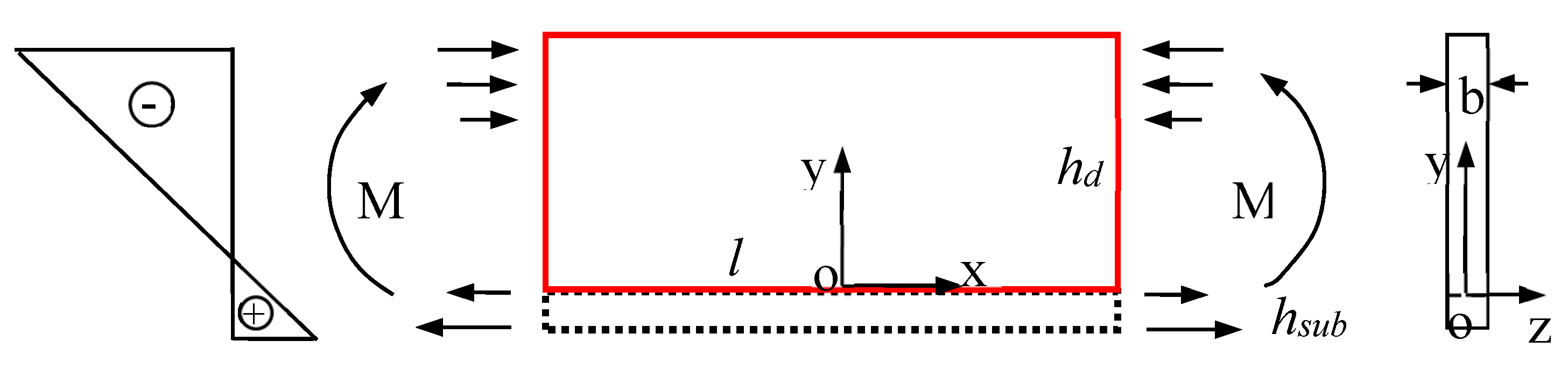
The deposited material is elastoplastic. The transverse stress is equal to the yield strength at the top layer in the XOY plane;
iii.
The base plate is rigidly clamped and in compression-stressed condition to balance the in-plane tensile stress of the single wall. We ignore the local plastic deformation under the weld pass;
iv.
We ignore the residual stress variation along thickness, and consider only the 2D in-plane stress distribution;
v.
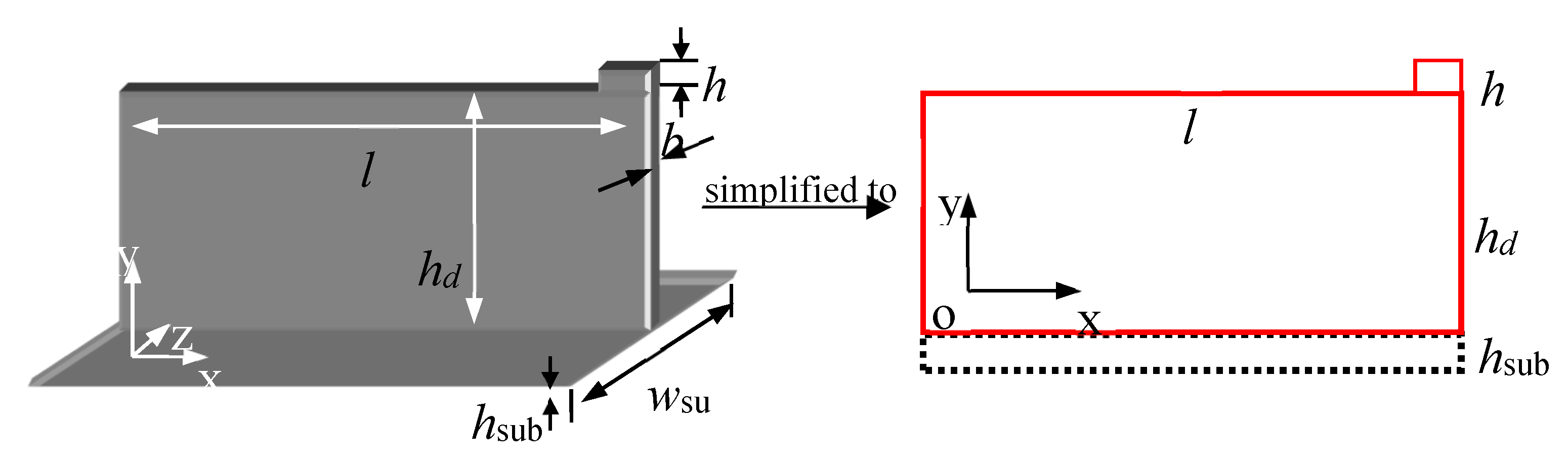
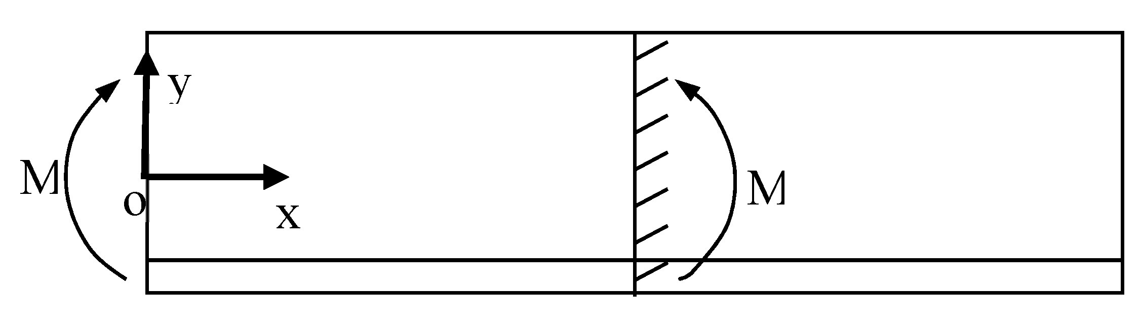
The structure can be abstracted as T-shape beam, so the general beam theory is available for warpage analyzation;
vi.
Warping occurs after removing the clamps, the bending moment is reduced to zero.
In the single-wall part, the nonuniform distribution of the residual stress from the bottom to the top layer is the precipitating factor of warpage—the effect of which is similar to the bending moment. A schematic illustration is shown in Figure 2. The symbol M denotes the bending moment.
The thickness of the single wall rib is constant. According to the hypothesis, the strain along the z direction caused by XOY plane stress is linearly varied, and the strain is coordinated in each interior profile along the z direction. Combined with the equilibrium differential equation, the compatibility equation without body force can be expressed as:
2 ( σ x + σ y ) = 0
2 ( ) is Laplacian operator. Assume φ = φ ( y ) is Airy stress function and plug it into Equation (6), σx, σy, τxy can be obtained:
σ x = 2 φ y 2 , σ y = 2 φ x 2 , τ x y = 2 φ x y
Referring to Mercelis and Kruth’s theoretical model [15], the strain is continuous in the whole XOY plane, so the Airy stress function can be expressed as:
φ = φ ( y ) = E ε x ( y ) = E ( A y + B )
where εx is strain distribution along x direction in the XOY plane. A and B are undetermined coefficients. It is easy to find that stress function Equation (8) satisfies the compatibility Equation (6). Hence, the solution of the stress component has monodromy in the solution domain. Under clamping, the following equilibrium equation of force and moment should be satisfied
σ x ( y ) d y = 0
σ x ( y ) y d y = 0
Because the clamping fixed base plate and additive manufactured single wall have different stiffness, stress variation is different in the two parts, at the junction of which, the stress is significant changed. Set m as the stiffness scale factor between base plate and the manufactured single wall rib, so m can be expressed as:
m = E s u b w s u b E d b
E is the elastic module; w is the width and b is the thickness of deposited wall part. The subscript sub denotes the base plate, which is shown in Figure 2. During the deposited process, the base plate was clamped on stainless steel work table, the elastic module and stiffness of which were much higher than the aluminum alloy base plate, so the base plate could be seen as rigid fixation and the tiny deformation neglected. The internal stress will accumulate to a high level for the displacement constraint. After removing the clamps, it can cause warping. The nonuniform thermal stress can produce a static bending moment. According to general beam theory, the warping analysis is equivalent to a rectangular beam bending problem, upon which, only linearly varied horizontal stress acts. No in-plane force acts on the surface and bottom, and no in-plane force acts on the side along vertical direction. The horizontal stress produces resultant couples at each side. Accordingly, the clamping produces a moment which is equal in magnitude, but in opposite direction. Hence, the internal stress is expressed using the moment:
σ x = M I y
I is the geometrical moment of inertia. For T cross profile, I is:
I = I s u b + I d
Here, I s u b = w s u b h s u b 3 12 + A s u b ( y T y s u b ) 2 , I d = b h d 3 12 + A d ( y T y d ) 2 . yT, yd and ysub are centroid vertical ordinates of the whole part, deposited wall part and base plate, respectively. Substitute these into Equation (12), the moment M can be calculated. The stress is calculated by simultaneously solving Equations (9) and (10).
According to the constitutive equation of in plane stress—and combined with geometric equation—the displacement along X direction (u) and Y direction (v) after removes the clamps are calculated by:
u = M E d I x y C y + u 0
v = υ 2 M E d I y 2 M 2 E d I x 2 + C x + v 0
For stress distribution shown in Figure 2, the longitudinal warping is similar to a vertical bending cantilever beam component, the fixed point of which is in the center, as shown in Figure 3.
The displacement boundary conditions of the cantilever beam end are:
u | x = l / 2 y = 0 = 0 ,   v | x = l / 2 y = 0 = 0 ,   v x | x = l / 2 y = 0 = 0
where u0, v0, C can be obtained by solving Equations (14) and (15).
{ u 0 = 0 v 0 = M l 2 8 E d I C = M l 2 E d I
The particular solution of Equations (14) and (15) are:
u = M E d I x y M 2 E d I y
v = υ 2 M E d I y 2 M 2 E d I x 2 + M l 2 E d I x M l 2 8 E d I
At the beam end, the warpage δ is obtained. According to the moment–curvature relationship, the curvature at the centerline also can be calculated.

2.2. Experimental Procedure

2.2.1. Additive Manufacturing Single Wall Rib

A ϕ 1.2 mm 5A06 aluminum alloy wire was selected as the raw material, and gas tungsten arc welding power (EWM, Tetrix 521 Synergic AC/DC) was used to carry out the experimental research. A numerical control machine tool (DMTG, Dalian, China) with four axes was used as a welding manipulator, where the welding torch was installed on the moving arm in downward position. The path direction was constant for the whole process. The dimension of base plate was 300 × 100 × 10 mm3, which was fixed on the work table. A rectangular pulse AC-power supply mode was adopted with peak and background current set as 160 A and 100 A, respectively. The wire feed speed was 2000 mm/min and the travel speed was 300 mm/min. The height of the deposited wall part was 100 mm.

2.2.2. Measurement Scheme of Residual Stress

The local residual stress was measured using the blind hole method. The resistance and sensitivity coefficient of foil strain gauge were 120 Ω and 2%, respectively. After drilling a 1-mm blind hole, strain in three direction was measured using a three-dimensional rosette gauge, and residual stress of this point was calculated. Eight measure points were designed in the center line, the first point was 20 mm away from the base plate surface, and then 10-mm hole spacing was designed. These values were used for residual stress theoretical model verification.

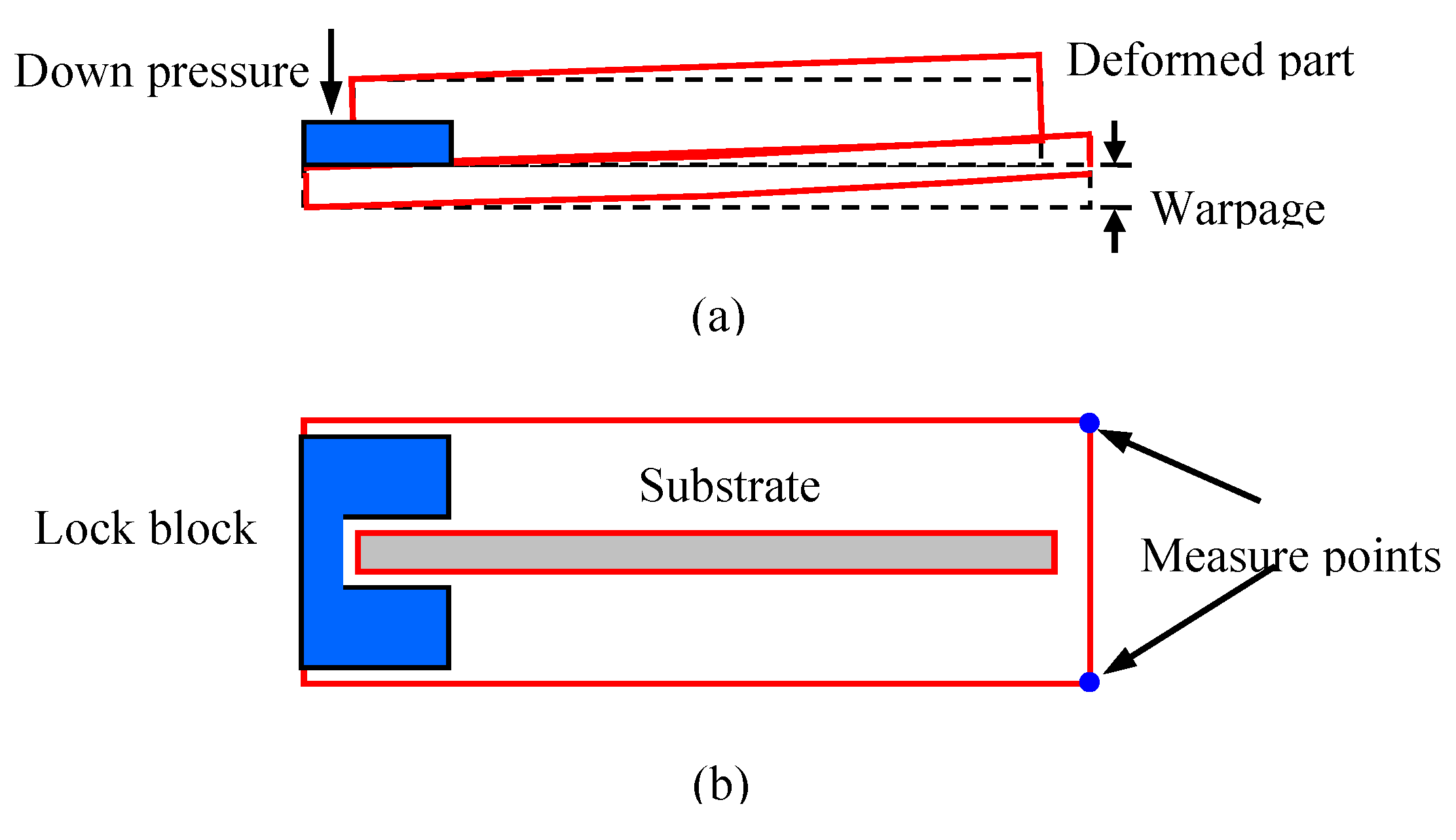
2.2.3. Measurement Scheme of Warpage

The single wall ribs with 5, 10, 15, 20, 25, and 30 layers were deposited using the process parameters described in Section 2.2.1. The additive manufactured parts were naturally cooled to room temperature and then the clamps were removed. The warpage was measured after 120 h of natural aging. The measuring method is shown in Figure 4.
A fixture was designed to measure the warpage, which had a horizontal base and plane clamping structure. The manufactured part was placed flat on the base and then the lock block clamped on one end, so the other side would upwarp. The vertical displacement of the two corners was measured. The same method was used to measure the other two. The average value of the four points was used for the verification.

3. Results and Discussion

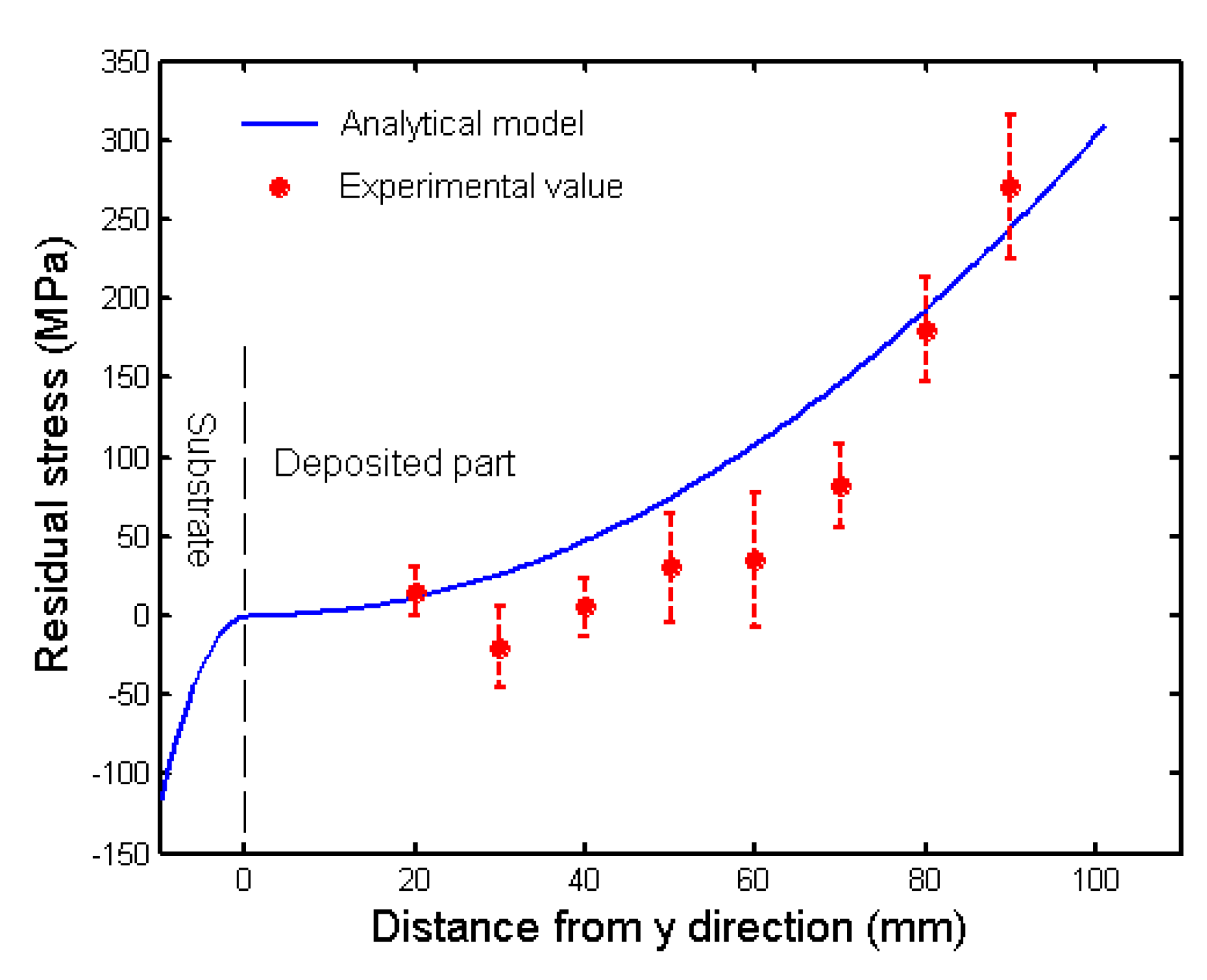
3.1. Theoretical Model Verification

According to the force and moment equilibrium condition, Equations (9) and (10) and substituting them into the boundary condition shown in Figure 1.
h s u b 0 m ( A y + B ) d y + 0 h d ( A y + B ) d y + h d h d + h σ x d y = 0
h s u b 0 m ( A y + B ) y d y + 0 h d ( A y + B ) y d y + h d h d + h σ x y d y = 0
According to the hypothesis, stress limitation in the top layer is yield strength. Substituting the value into the above formulas, coefficients A and B are calculated, which correspond to the total deposition height. Then, the stress distribution in the XOY plane along X direction at any height is obtained:
σ x = 1 3 2 m A h s u b 3 3 m B h s u b 2 + 2 A h d 3 + 3 B h d 2 h ( 2 h d + h ) = 1 2 m A h s u b 2 2 m B h s u b A h d 2 2 B h d h
The stress distribution is shown in Figure 5 for a 100-mm high structure. Higher than 30 mm—i.e., more than 30 layers—the stress sharply increased to the yield strength of 300 MPa. After cyclic post-heating of the electrical arc, the layers’ stress under the molten pool released gradually, the value was very close to zero. The base plate was in compression-stressed condition to balance tensile stress in the single wall. Although the calculated values slightly deviated from the blind-hole-tested stress values, the change law along central line from bottom to top layer was similar. This also demonstrated the validity of the theoretical model, because the inevitable errors of residual stress measurement.

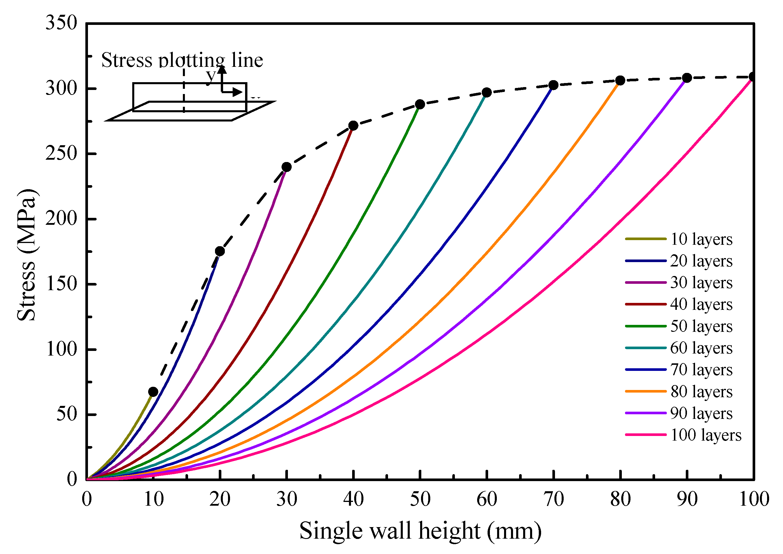
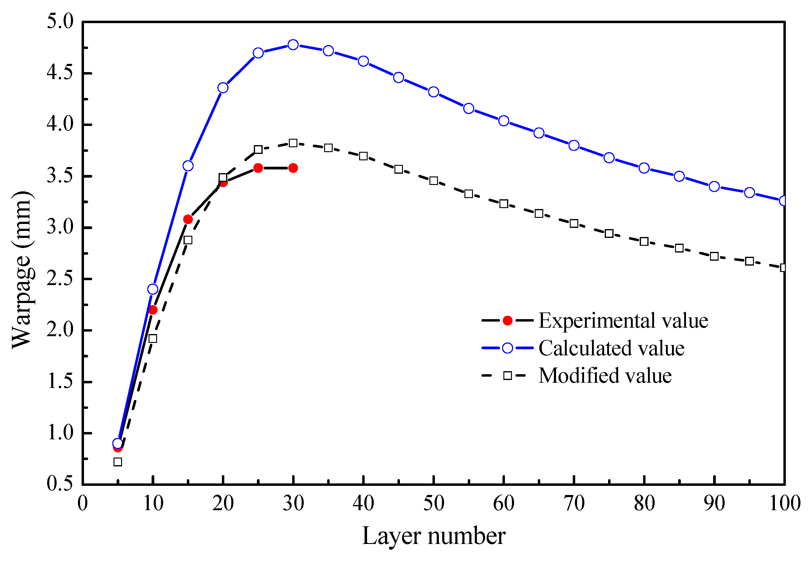
3.2. Stress and Warpage Evolution

A group of experiments were designed with different layers, 5, 10, 15 … 100, and equation coefficients A and B for different wall height were calculated. These are listed in Table 1.
Taking these coefficients into the stress equilibrium equation, the stress evolution for different wall height was obtained, as shown in Figure 6. The stress distribution along central line for different height and stress evolution in the top layers are plotted.
During continuous additive manufacturing, tensile stress across top layer increases and the stress gradient gradually become higher, the limitation of which was yield strength of the as-deposited materials. After each layer deposition, the substituted post-heating promoted the temperature uniformity of the deposited part. After 100 layers of deposition, the top-layer-plane stress in the 10th layer decreased from 68 MPa to 5 MPa; the plane stress in the 20th layer decreased from 175 MPa to 16 MPa; the plane stress in the 30th layer decreased from 239 MPa to 23 MPa; the plane stress in the 40th layer decreased from 266 MPa to 44 MPa; the plane stress in the 50th layer decreased from 277 MPa to 71 MPa; the plane stress in the 60th layer decreased from 282 MPa to 88 MPa; the plane stress in the 70th layer decreased from 295 MPa to 137 MPa; the plane stress in the 80th layer decreased from 296 MPa to 162 MPa and the plane stress in the 90th layer decreased from 296 MPa to 245 MPa. The stress gradient gradually became lower as the deposited wall part grew tall. Post heating treatment effect was important for temperature uniformity. Therefore, electrical arc heating after each layer deposition may be a practicable process procedure to ameliorate the stress level.
Under 40 layers, the stress in the top layer rapidly increased to the yield strength. With continuous deposition, the stress increased slowly and gradually reaches to a constant value. That indicates the temperature distribution became stable at the moment, and the temperature inhomogeneity feature was unchanged. Hence, the stress amplitude in the upper part was unchanged, but as the total height increased, the stress gradient descended accordingly. The bending moment produced by nonuniform stress field changed slowly, which was determined by the stress gradient. It was speculated that the maximum warping occurred before 40 layers of deposition under the given processing conditions. With more than 40 layers, the bending moment showed little change, but the wall height increased, i.e., as the geometrical moment of inertia increased, so did the stiffness of the whole part. When stiffener was designed higher than 40 layers, the warpage would be reduced under this experimental condition. Figure 7 shows the experimental and calculated warpage.
In the bending process, plastic deformation can release residual stress, but in fact, the deformation is not enough to release all of the stress in the wall, some of which is still resides in the part. However, the residual is unknown for different structure patterns. Hence, we assume that the residual stress reduces to zero and the bending moment reduces to zero after warping in Section 2.1, but in fact, some of stress is still residual in the part, so the calculated warpage is greater than experimental result. In Figure 7, one may notice that they show similar variation law. On the basis of the above analysis, a correction factor 0.8 is advised. As shown in Figure 7, the modified value shows favorable agreement with experimental data.
After correction, the largest warpage happened when the stiffener was designed with 30 layers—the largest warpage was 3.48 mm. This result is consistent with the residual stress analysis. The warpage reduced with the decrease of layers because of lower residual stress; the warpage increased with layer increase because of higher stiffness.

4. Conclusions

In the study, a theoretical model of stress and warpage was developed for additive manufacturing stiffened panel structures. The nonuniformity of plane horizontal stress produces a torque, bending the ribbed slab. This is be equivalent to vertical bending of a cantilever beam; hence warpage could be calculated using the general beam theory. Furthermore, a stress model was set up without a distributional hypothesis, which was obtained basing on force and moment balance.
The results showed that with fewer than 40 layers, stress in the top layer rapidly increased to the yield strength. With continuous deposition of up to 100 layers, the stress increased slowly and gradually trended to a constant. The bending moment showed little change, but the geometrical moment of inertia increased. After 100 layers of deposition, the top-layer-plane stress in the 10th layer decreased from 68 MPa to 5 MPa, and the plane stress in the 90th layer decreased from 296 MPa to 245 MPa. The post-heating treatment effect is important for temperature uniformity. The largest warpage happened when the stiffener was designed with 30 layers—the greatest warpage was 3.48 mm. This result was consistent with residual stress analyses. The warpage reduced with layer decrease because of lower residua stress, and the warpage increased with layer increase because of higher stiffness.

Author Contributions

Data curation, J.G.; formal analysis, H.G. and J.L.; funding acquisition, X.L.; methodology, H.G. All authors have read and agreed to the published version of the manuscript.

Funding

This work was supported by the National Natural Science Foundation of China (Grant No. 51805088), the fund of the State Key Laboratory of Solidification Processing in NWPU, (Grant No. SKLSP201914) and Fuzhou University Testing Fund of precious apparatus, (Grant No. 2019T010).

Conflicts of Interest

The authors declare no conflict of interest.

References

  1. Zhang, Y.M.; Chen, Y.; Li, P.; Male, A.T. Weld deposition-based rapid prototyping: A preliminary study. J. Mater. Process. Technol. 2003, 135, 347–357. [Google Scholar] [CrossRef]
  2. Chen, J. Hybrid Design Based on Wire and Arc Additive Manufacturing in the Aircraft Industry. Master’s Thesis, Cranfield University, Bedford, UK, 2012; pp. 1–3. [Google Scholar]
  3. Ding, D.H.; Pan, Z.X.; Cuiuri, D.; Li, H.J. Wire-feed additive manufacturing of metal components: Technologies, developments and future interests. Int. J. Adv. Manuf. Technol. 2015, 81, 465–481. [Google Scholar] [CrossRef]
  4. Chen, H.; Xu, Y.M.; Hu, J.H. Optimization of lightweight sub-stiffened panels with buckling analysis and imperfection sensitivity analysis. Proc. Inst. Mech. Eng. Parts G J. Aerosp. Eng. 2019, 223, 5507–5521. [Google Scholar] [CrossRef]
  5. Li, F.; Chen, S.J.; Shi, J.B.; Tian, H.Y.; Zhao, Y. Evaluation and optimization of a hybrid manufacturing process combining wire arc additive manufacturing with milling for the fabrication of stiffened panels. Appl. Sci. Basel 2017, 7, 1233. [Google Scholar] [CrossRef] [Green Version]
  6. Li, R.; Xiong, J.; Lei, Y.Y. Investigation on thermal stress evolution induced by wire and arc additive manufacturing for circular thin-walled parts. J. Manuf. Process. 2019, 40, 59–67. [Google Scholar] [CrossRef]
  7. Shen, C.; Reid, M.; Liss, K.D.; Pan, Z.X.; Ma, Y.; Cuiuri, D.; Van Duin, S.; Li, H.J. Neutron diffraction residual stress determinations in Fe3Al based iron aluminide components fabricated using wire-arc additive manufacturing (WAAM). Addit. Manuf. 2019, 29, 100774. [Google Scholar] [CrossRef]
  8. Fawad, H.; Mughal, M.P.; Mufti, R.A. Effect of constraint on residual stresses and deformations in weld based rapid prototyping. In Proceedings of the 3rd International Conference on Advanced Research in Virtual and Rapid Prototyping: Virtual and Rapid Manufacturing, Advanced Research Virtual and Rapid Prototyping, Leiria, Portugal, 24–29 September 2007; pp. 629–634. [Google Scholar]
  9. Klingbeil, N.W.; Beuth, J.L.; Chin, R.K.; Amon, C.H. Residual stress-induced warping in direct metal solid freeform fabrication. Int. J. Mech. Sci. 2002, 44, 57–77. [Google Scholar] [CrossRef]
  10. Vasinonta, A.; Beuth, J.; Griffith, M. Process maps for controlling residual stress and melt pool size in laser-based SFF processes. In Proceedings of the Solid Freeform Fabrication Symposium, Austin, TX, USA, 7–9 August 2000; pp. 200–208. [Google Scholar]
  11. Huang, H.; Chen, J.; Carlson, B.E.; Wang, H.P.; Crooker, P.J.; Frederick, G.; Feng, Z. Stress and distortion simulation of additive manufacturing process by high performance computing. In Proceedings of the ASME Pressure Vessels and Piping Conference, Prague, Czech Republic, 15–20 July 2018. [Google Scholar]
  12. Camilleri, D.; Comlekci, T.; Gray, T.G.F. Computational prediction of out-of-plane welding distortion and experimental investigation. J. Strain Anal. Eng. Des. 2005, 40, 161–176. [Google Scholar] [CrossRef]
  13. Withers, P.; Bhadeshia, H. Residual stress, part 2-nature and origin. Mater. Sci. Technol. 2001, 17, 366–375. [Google Scholar] [CrossRef]
  14. Pister, K.S.; Dong, S.B. Elastic bending of layered plates. ASCE J. Eng. Mech. Div. 1959, 84, 1–10. [Google Scholar]
  15. Mercelis, P.; Kruth, J.P. Residual stresses in selective laser sintering and selective laser melting. Rapid Prototyp. J. 2006, 12, 254–265. [Google Scholar] [CrossRef]
Figure 1. Schematic illustration of the simplified two-dimensional elastic plane.
Metals 10 00666 g001
Figure 2. Schematic illustration of the bending moment caused by in-plane residual stress.
Metals 10 00666 g002
Figure 3. Schematic illustration of equivalent vertical bending cantilever beam.
Metals 10 00666 g003
Figure 4. Schematic showing the measuring method of warpage. (a) side view and (b) top view.
Metals 10 00666 g004
Figure 5. Stress comparison of analytical and experimental value along central line.
Metals 10 00666 g005
Figure 6. Stress distributions along central plot line during additive manufacturing process.
Metals 10 00666 g006
Figure 7. Warpage comparisons between the calculated and experimental value.
Metals 10 00666 g007
Table 1. Stress equation coefficients and warpage with different layers.
Layer NumberEquation CoefficientsWarpage (mm)
AB
5−0.5686−2.75460.9
10−0.7295−3.08752.4
15−0.7278−2.85263.6
20−0.6396−2.36924.36
25−0.5323−1.87734.70
30−0.4357−1.46574.78
35−0.3569−1.14394.72
40−0.2948−0.89744.62
45−0.2462−0.70824.46
50−0.2080−0.70824.32
55−0.1776−0.44704.16
60−0.1533−0.35584.04
65−0.1334−0.28243.92
70−0.1172−0.22263.80
75−0.1036−0.17343.68
80−0.0923−0.13243.58
85−0.0827−0.09803.50
90−0.0754−0.06883.40
95−0.0675−0.04393.34
100−0.0614−0.02253.26

