Article

Effect of Post Processing Heat Treatment Routes on Microstructure and Mechanical Property Evolution of Haynes 282 Ni-Based Superalloy Fabricated with Selective Laser Melting (SLM)

J. B. Speed School of Engineering, University of Louisville, Louisville, KY 40292, USA
*
Author to whom correspondence should be addressed.
Metals 2020, 10(5), 629; https://doi.org/10.3390/met10050629
Submission received: 4 April 2020 / Revised: 8 May 2020 / Accepted: 10 May 2020 / Published: 12 May 2020

Abstract

:
Selective laser melting (SLM) is one of the most widely used additive manufacturing technologies. Fabricating nickel-based superalloys with SLM has garnered significant interest from the industry and the research community alike due to the excellent high temperature properties and thermal stability exhibited by the alloys. Haynes-282 alloy, a γ′-phase strengthened Ni-based superalloy, has shown good high temperature mechanical properties comparable to alloys like R-41, Waspaloy, and 263 alloy but with better fabricability. A study and comparison of the effect of different heat-treatment routes on microstructure and mechanical property evolution of Haynes-282 fabricated with SLM is lacking in the literature. Hence, in this manuscript, a thorough investigation of microstructure and mechanical properties after a three-step heat treatment and hot isostatic pressing (HIP) has been conducted. In-situ heat-treatment experiments were conducted in a transmission electron microscopy (TEM) to study γ′ precipitate evolution. γ′ precipitation was found to start at 950 °C during in-situ heat-treatment. Insights from the in-situ heat-treatment were used to decide the aging heat-treatment for the alloy. The three-step heat-treatment was found to increase yield strength (YS) and ultimate tensile strength (UTS). HIP process enabled γ′ precipitation and recrystallization of grains of the as-printed samples in one single step.

1. Introduction

Nickel-based superalloys have excellent high temperature properties and thermal stability. Hence, they are widely used for high temperature applications like gas turbines, space vehicles, nuclear reactors, heat-exchangers, etc. For such low production run applications, additive manufacturing technologies have several advantages over conventional manufacturing methods. Due to this, additive manufacturing of nickel-based superalloys has garnered interest from the industry and the research community alike. Selective laser melting (SLM) is one of the most widely used additive manufacturing technologies in which metal powders are used as starting material and a component is fabricated by fusing together layers of metal powder using a high-power laser. Inconel 718 [1,2], Inconel 625 [3,4], Hastealloy-X [5], Nimonic-263 [6], Waspaloy [7], and several other Ni-based superalloys have been fabricated with SLM and the post manufacturing mechanical properties and microstructure have been studied in detail. The microstructure of as-printed Ni-based superalloys is characterized by formation of elongated grains in the build direction and dendritic phase. The inter-dendritic region consists of heavy elements like Mo and Nb [1,8,9]. To precipitate the hardening phases (γ′ in case of alloys like Inconel 738 [10] or γ′’ in case of alloys like Inconel 718 [11]), a two- or three-step heat-treatment process is typically used. The first step is the solutionizing step followed by one or two aging steps. Hardening phases precipitate after the first aging step (or second heat treatment step). The second aging step (or the third heat treatment step) results in coarsening of the γ′-phase and also in increasing its volume fraction. These hardening phases provide high temperature strength to the superalloys [1,3,11,12].
Some Ni-based superalloys, especially the ones with higher Al and Ti content (typically >6%) are prone to cracking when fabricated with SLM [10,13,14]. Hot isostatic pressing (HIP) is a heat-treatment process that not only alters the microstructure of Ni-based superalloys, but also helps to eliminate fabrication defects like cracking and porosity [11,14,15]. Elevated temperature and pressure during HIP promote filling of pores and cracks formed during the fabrication process.
Haynes-282, a newly developed Nickel based superalloy, has been shown to exhibit good mechanical properties and fabricability [16]. The ordered γ′ (Ni3Al, Ti) phase provides high temperature strength and creep resistance, while the carbides segregated at grain boundaries help to further improve the creep resistance [17]. The precipitated γ′ phase resides within the matrix γ-phase and a cube–cube orientation relationship exists between the two, similar to other Ni-based superalloys. Haynes-282 provides high temperature yield strength, creep strength, and thermal stability comparable to other Ni-based superalloys like R-41, Waspaloy, and 263 alloy, but with better fabricability [18,19]. This high strength can be achieved with Haynes-282 with a lower γ′ volume fraction [20]. Direct laser metal deposition of Haynes-282 has been investigated [21], but SLM of Haynes-282 has not been investigated in the literature, especially in the context of microstructure and physical properties and their dependence on post-fabrication heat-treatment route. A complete understanding of these dependences will allow an informed choice of the post-processing route and will enable wide-spread use of SLM for fabrication of Haynes-282 components, especially in the aerospace and thermal power plant industry where Haynes-282 is frequently used.
Therefore, in this work, as-printed Haynes-282 was subjected to in-situ heat-treatment with a transmission electron microscope (TEM). The results obtained provide insight into the microstructural evolution mechanism during heat-treatment. Ex-situ analysis of microstructure and mechanical properties was conducted during a three-step heat-treatment process and post-HIP treatment. For the first time, HIP of Haynes-282 fabricated with SLM has been investigated in this manuscript. The investigation provides an understanding of the effect of different heat-treatment routes on the microstructure and mechanical properties, and a thorough comparison between the different routes.

2. Materials and Methods

Size distribution of the Haynes-282 powder used in all the experimental runs and the chemical composition of the powder as received from the manufacturer have been given in Table 1 and Table 2, respectively. All the components were fabricated using Concept Laser Mlab metal additive manufacturing machine, which utilizes a 100-W continuous wave Yb fiber laser. Laser scan lines in successive layers make +45°/−45° angle with the X- or Y-direction. Process parameters optimized to eliminate porosity and other defects in the samples were used to fabricate 10-mm cubes and tensile test coupons. These optimized process parameters are listed in Table 3. The optimized process parameters resulted in negligible porosity (around 0.3%) in the as-printed condition. The porosity was measured using optical imaging, followed by image analysis in ImageJ software.

2.1. Heat Treatment

Ten-millimeter cubes fabricated with optimized process parameters were subjected to a 3-step heat treatment process, which involved a solutionizing treatment and two aging steps. First step (solutionizing treatment) involved heating the samples to 1120 °C for 2 h followed by water quenching. Next step (Aging step 1), determined based on the insights from in-situ heat-treatment experiments, involved heating the samples to 1000 °C for 2 h followed by furnace cooling, while the last step (Aging step 2) involved heating the samples to 788 °C for 8 h followed by furnace cooling. After each heat treatment step, cross-section of one cube was cut and polished to analyze the microstructure and hardness. HIP treatment of the as-printed samples was performed at 1185 °C and 150 MPa pressure for 3.5 h. Table 4 shows the details of the two heat treatment routes used.

2.2. Microstructure Analysis

Cross-sections of as-printed samples and of samples after every heat treatment step were polished by successively using 240, 600, and 1200 grit abrasive discs. Final polishing was performed progressively with 1-micron diamond slurry, 0.02-micron colloidal silica, and vibratory polishing. Electron backscatter diffraction (EBSD) analysis and hardness measurements of the samples were performed post-polishing. Polished cross-sections were also electro-chemically etched using a γ-phase etchant consisting of chromic acid (H2CrO4) made from 15 g chromium oxide (CrO3) and 10 mL sulfuric acid (H2SO4) dissolved in 150 mL phosphoric acid (H3PO4), and SEM images of the etched samples were taken to analyze the microstructure. ImageJ software was used to perform image analysis to determine size of microstructural phases.

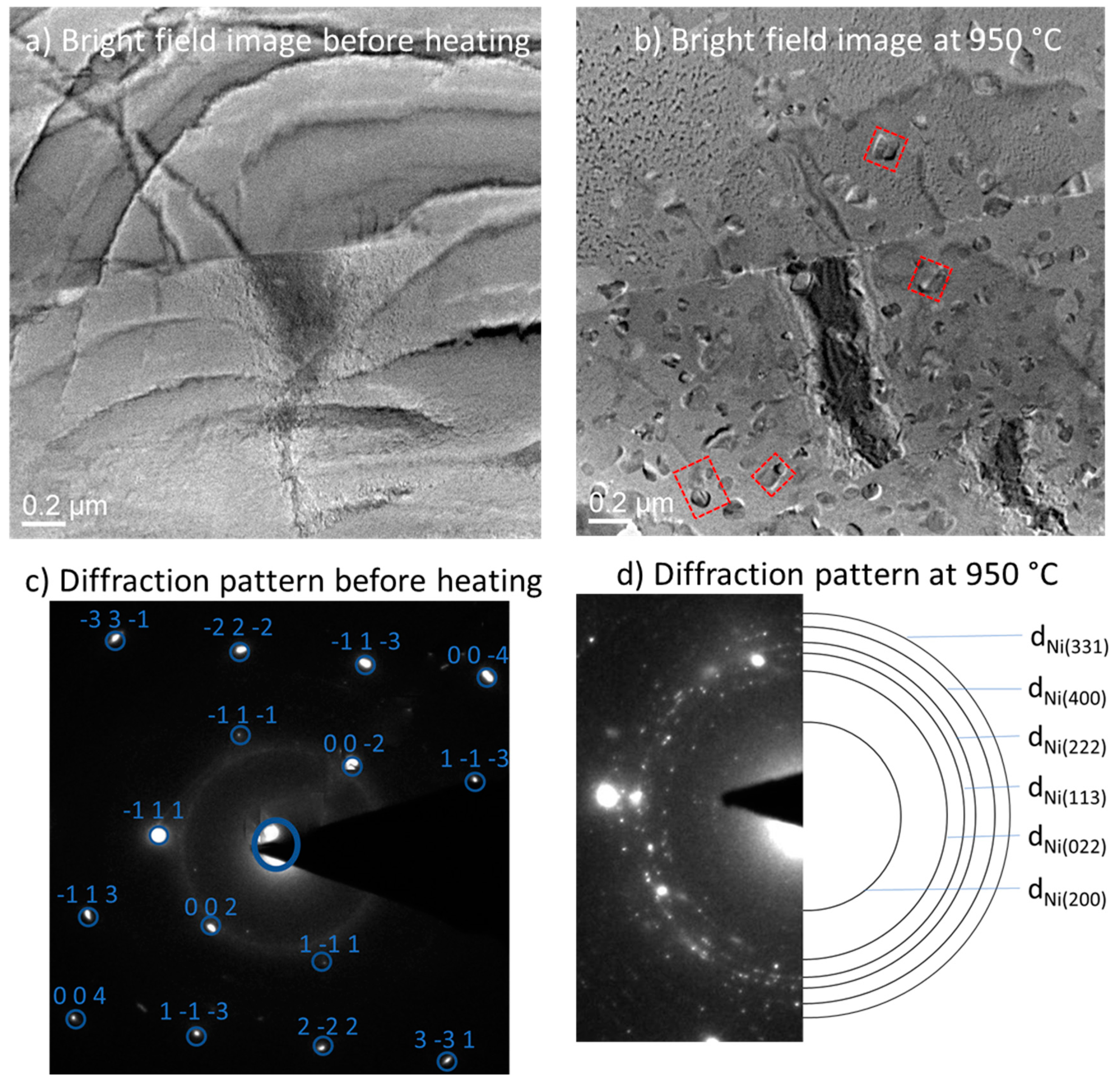
2.3. In-Situ TEM Analysis

After performing the solutionizing step, a focused ion beam (FIB) was used to prepare TEM samples. An in-situ heating sample holder was used to heat the samples and observe them in a Tecnai G2 TEM. Periodically, during the in-situ heating, bright field images and diffraction patterns were recorded.

2.4. Hardness Measurement

Vickers hardness tests were performed on samples after each heat-treatment step. Ten micro-indents were made at random locations on polished X-Y cross sections of each sample using a force of 2.94 N and 10 s hold. The mean of the length of two diagonals of the indents was calculated to obtain the hardness values using the formula H V = 2 F sin ( 136 2 ) d 2 , where F is the force in kgf and d is the mean of the lengths of two diagonals of the indents.

2.5. Tensile Testing

Tensile test coupons with longitudinal axis perpendicular to Z-direction were fabricated with the optimized process parameters. Dimensions of the coupons were determined using ASTM E8 specifications. Tensile tests were conducted in an Instron 8800 machine at a strain rate of 0.001/s on as-printed test coupons and coupons subjected to 3-step heat treatment and HIP treatment. Four replicate tests were conducted for each step.

3. Results and Discussion

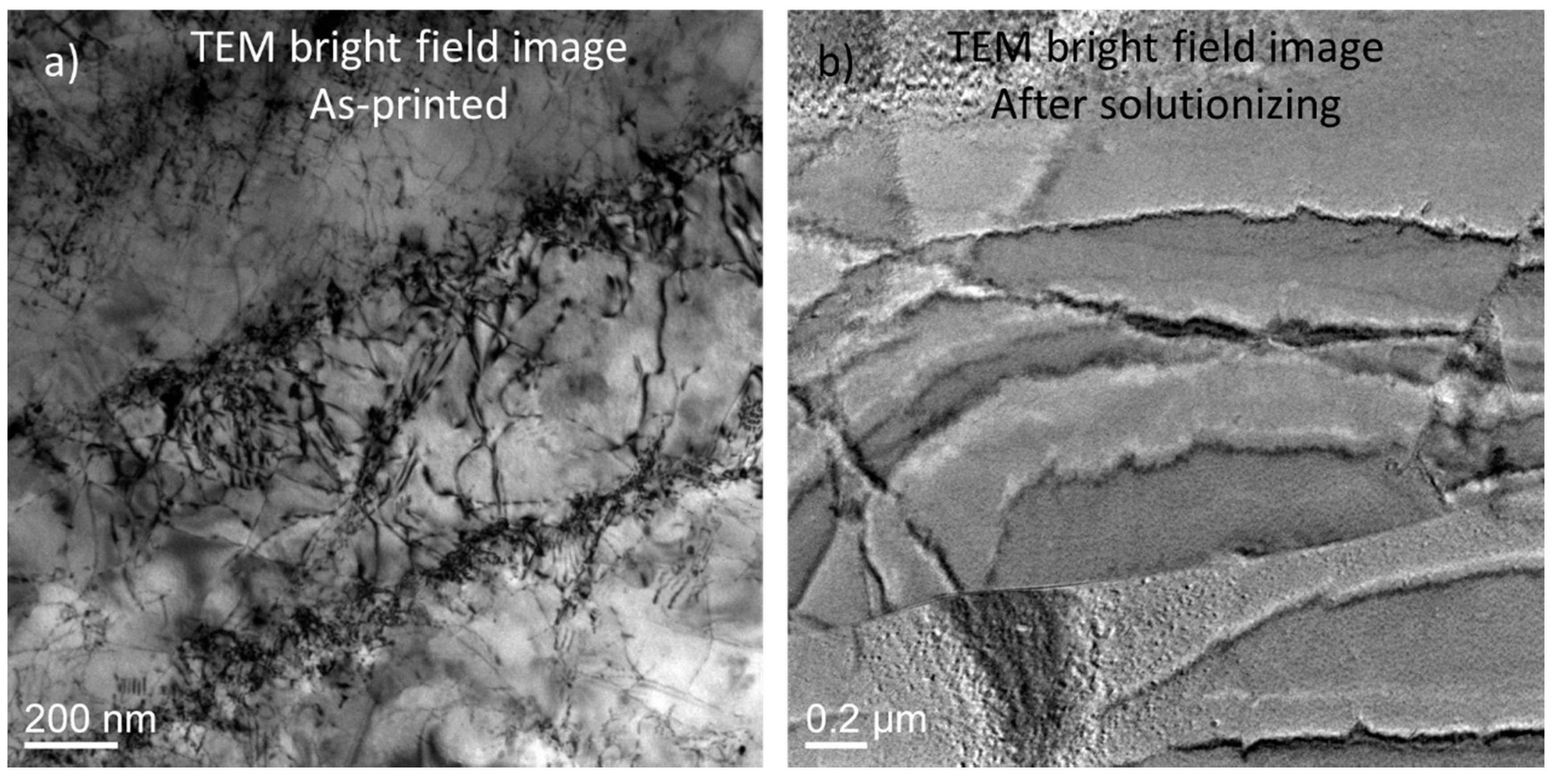
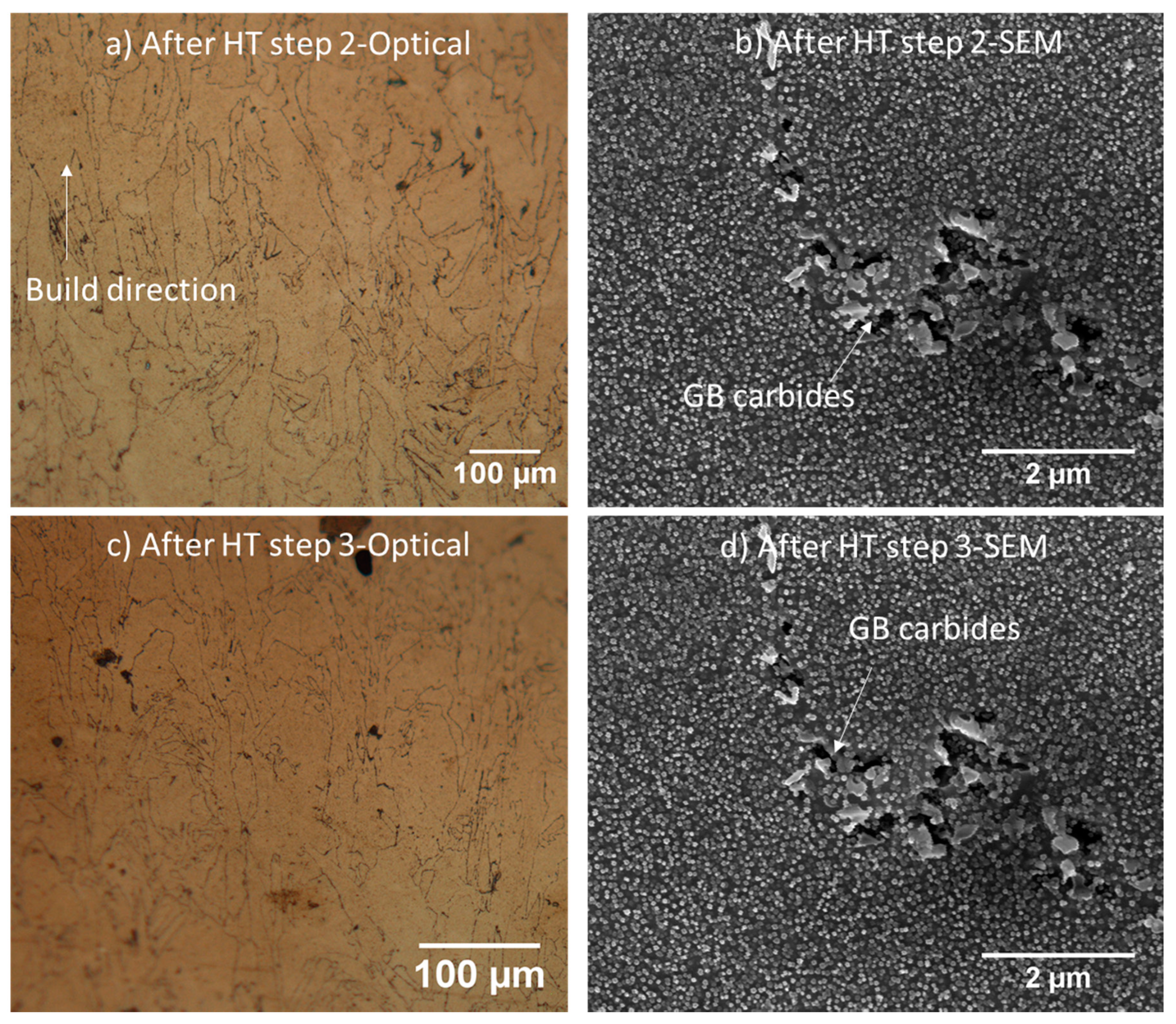
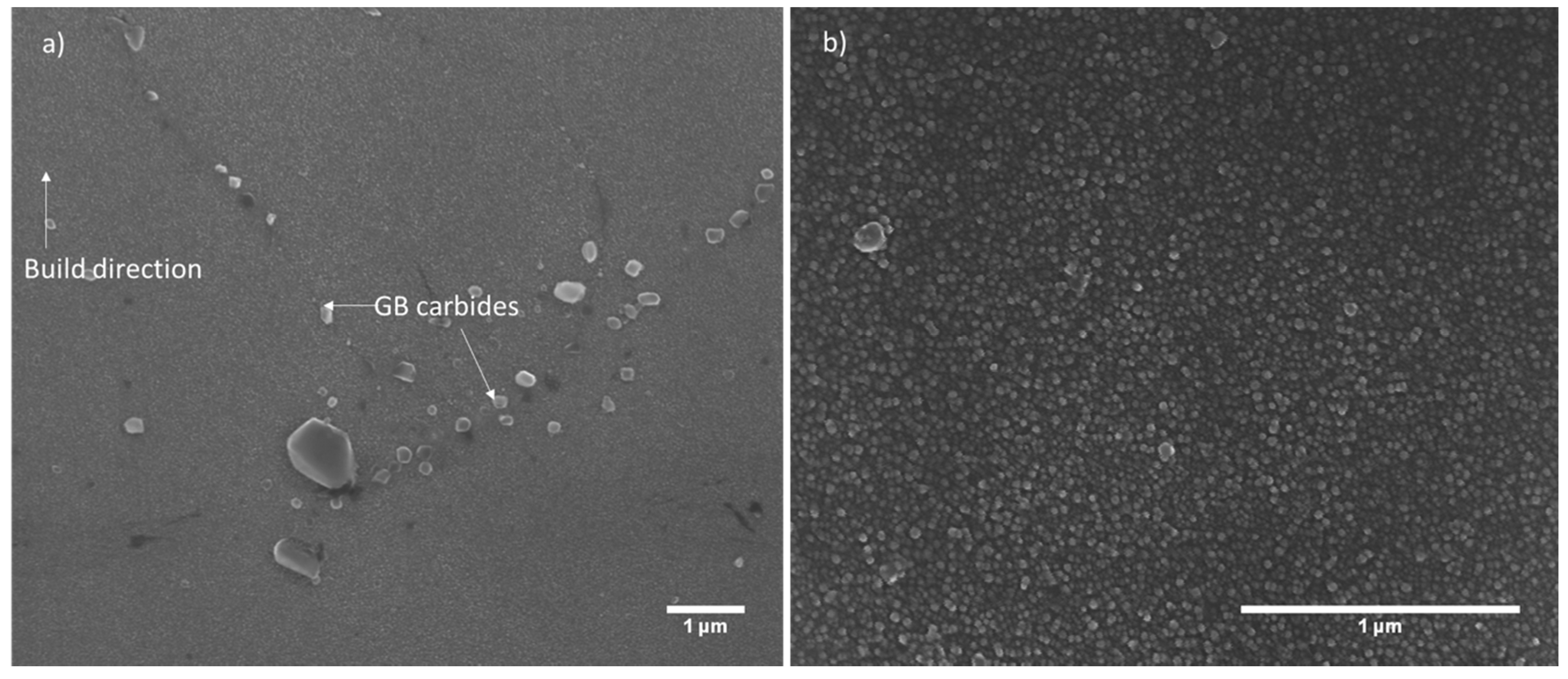
3.1. Microstructure Analysis
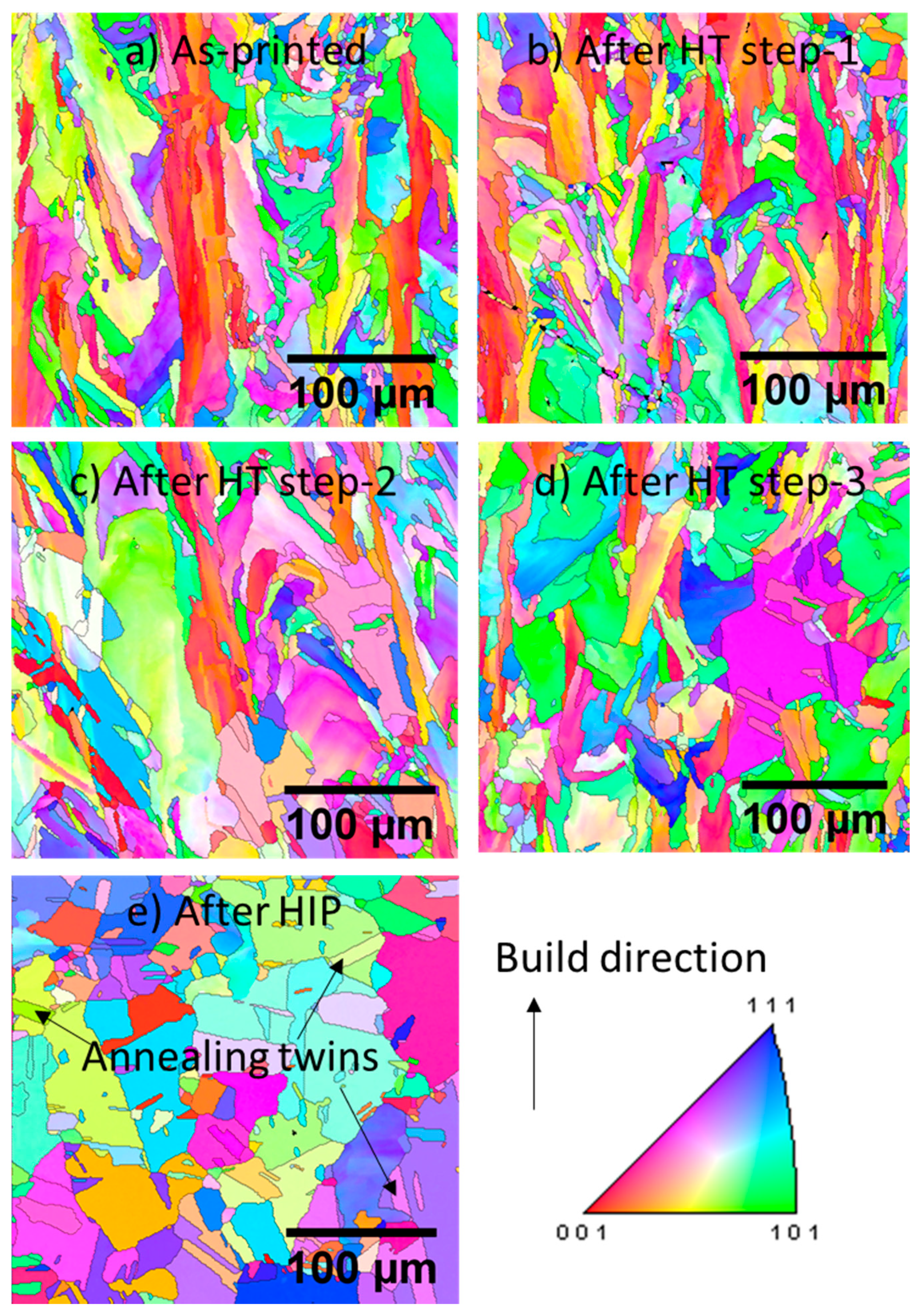
Figure 1a,b show the microstructure of an as-printed sample. Typical dendritic/cellular segregation is evident from the figure. This is a result of extremely fast cooling rates during the SLM process. During fast solidification, heavier solutes, predominantly Mo in this case, get pushed out and segregated from the melt pool forming these dendritic regions within each grain. Figure 1b shows an image at a melt-pool boundary in which the elongated and polygonal shape of the dendrites on either side of the melt pool is clearly evident. Elongated shape of dendrites in one melt-pool is due to cross-section cut parallel to the dendrites in that melt-pool versus the polygonal shape in the other melt-pool, which is due to the cross-section cut perpendicular to the length of the dendrites in that melt-pool. No evidence of any other phases (like γ′) was observed in the as-printed samples (TEM bright field image of as-printed sample shown in Figure 2a also did not show any evidence of γ′). The dendritic phase, also called as Laves phase, has been observed to hamper high-temperature properties and fatigue behavior of Ni-based superalloys [22,23]. Hence, these phases need to be dissolved in the γ matrix. For this, the samples were subjected to solutionizing treatment. Figure 1c,d show the microstructure of a sample after it has gone through solutionizing step (or heat-treatment step-1). Solutionizing dissolved the segregated dendritic phase in the matrix γ-phase and resulted in the precipitation of inter-granular and intra-granular metal carbides (or MC carbides), which are characterized by their peculiar morphology. These MC carbides are Cr, Mo, and Ti rich M6C and M23C6 carbides [16,24,25].
The TEM image of as-printed sample shown in Figure 2a exhibits a very high dislocation density induced in the samples due to repeated cyclic heating and fast-cooling. The TEM micrograph also shows segregation of higher density elements that form the dendritic phase. As seen in Figure 2b, the sample preserves a large amount of residual stress despite having gone through the solutionizing step. This residual stress, which is a remnant of the inherent thermal stresses in the SLM process, causes the TEM lamella to bend, resulting in the appearance of bending contours in the bright field image. But after solutionizing, dislocation density appears to have significantly reduced along with dissolution of dendritic phase.
After the solutionizing step, TEM samples were subjected to in-situ heat treatment to analyze precipitation and to determine the temperature at which the precipitation begins. Figure 3a shows a bright field TEM image of the sample before the start of in-situ heating. Diffraction pattern obtained before the start of in-situ heating shows very distinct diffraction spots as seen in Figure 3c. During in-situ heating, when the temperature reaches 950 °C, small precipitates start to appear in the bright field image. The diffraction pattern also changes from distinct diffraction spots to speckled rings. Indexing of these speckled rings revealed the presence of only FCC phases in the sample. This indicates that the precipitates observed in the bright-field image are γ′ precipitates, which also have FCC crystal structure but have lattice spacing slightly different than the matrix γ-phase.
Within a short period of 10 min after precipitation, precipitates grow rapidly, some growing to a diameter of ~130 nm. The average size in 10 min is ~75 nm. After this, the coarsening mechanism of γ′ particles slows down significantly. For the time of the test, continued heating does not significantly increase the size of the precipitates once they reach a maximum size of ~130 nm. With continued heating, new precipitates nucleate and the volume fraction of these increases.
According to the coarsening theory developed by Lifshitz-Slyozov and Wagner, called the LSW theory, the size of precipitates during heat-treatment is given by r t 3 r 0 r = k × t , where r t is the mean particle size at time t, r 0 is the mean particle size at time t = 0, and k is the coarsening constant [26]. k depends on the atomic fraction of the solute, precipitate/matrix interface energy, molar volume of precipitates, and on the temperature. Rapid initial growth of the precipitates is clearly an aberration to the LSW theory. This rapid growth can be attributed to 2 mechanisms. The first mechanism contributing to rapid initial γ′ coarsening is the coalescence of γ′ particles which are in close vicinity of one another, similar to that observed by Meher et al. [26]. Evidence of this coalescence can be seen in Figure 3b, where pairs of particles joining to form one larger particle are highlighted by dotted lines in the image. Since only a few particles are seen coalescing, this cannot be the only mechanism responsible for rapid coarsening. The second mechanism is the reduction in value of k with an increase in precipitate volume fraction observed in Ni3Al precipitates [27]. As the elastic interactions between the γ′ precipitates increase with an increase in γ′ volume fraction, these interactions retard the coarsening of the particles. This effect has been observed to be drastic for γ′ volume fractions less than 0.05 [27].
Based on these in-situ heating results, solutionized samples were heated at 1000 °C (50 °C above the temperature at which γ′ precipitation was observed in in-situ heating experiments) for 2 h. Figure 4 shows optical and SEM images of the microstructure of a sample that has gone through this 2nd heat-treatment step. A high γ′ fraction can be observed along with inter-granular carbides at the grain boundaries. Image analysis with ImageJ software revealed that the shape of γ′ precipitates is predominantly spherical with an average diameter of 60 nm, while the maximum diameter observed is ~130 nm, similar to that observed in the in-situ experiments. Despite having gone through heat-treatment for 2 h, the average size is smaller than that observed in the in-situ experiments. This is because, during the cooling period, fine γ′ particles are formed [28]. These particles, called cooling γ′, skew the average particle size below the average observed in in-situ experiments. The observation of γ′ precipitates after the 2nd heat-treatment step in-situ and ex-situ is in contrast with the observations made by Joseph et al. [16]. In their work, no γ′ precipitates were observed after mill annealed Haynes-282 samples were subjected to solutionizing and aging step. γ′ precipitates were observed by Joseph et al. only after the 3rd heat-treatment step (or 2nd aging step).
After the 3rd step (final step), the shape of γ′ precipitates did not change but γ′ average diameter was observed to be 68 nm, only slightly higher than that observed post 2nd step. No change in the shape of the γ′ particles indicates that the coarsening mechanism, however slight the coarsening, was predominantly Ostwald ripening, a competitive coarsening mechanism, which reduces the specific area of γ- γ′ interface [29]. All γ′ particles were observed to be lesser than the critical size for Orowan looping, doro = 201 nm [16], which is the critical diameter above which Orowan looping is observed. A consequence of this is that the dislocation motion across the γ′ precipitates during plastic deformation can happen only by particle shearing. The effect of this on the deformation behavior and mechanical properties is discussed in the “Mechanical Properties” section.
Figure 5 shows the microstructure of samples after HIP treatment. Because the porosity in the as-printed condition was negligible to begin with, a significant change in porosity was not observed after HIP. During HIP treatment, the dendritic phase formed during the SLM process dissolves in the γ matrix and also precipitates γ′ phase. The size of γ′ precipitates (~10 nm average diameter) is much smaller than that observed after the 2nd and 3rd heat-treatment steps described above. Figure 5a shows the grain boundary carbides formed during HIP treatment. These carbides have been shown to improve creep resistance [17]. Evidently, HIP processing achieves γ′ precipitation in a single step for Haynes-282, unlike the heat-treatment process described above, which requires the solutionizing step first and then an aging step to precipitate γ′ phase. In case of HIP treatment also, the size of γ′ precipitates is smaller than the critical size for Orowan looping, hence the deformation will happen by particle shearing [16].
The coarsening of γ′ precipitates is a diffusion driven phenomenon. The as-printed samples have a non-homogenous distribution of solutes in the matrix as seen in Figure 1b, resulting in a dearth of γ′ promoting elements in the matrix. Also, at high pressures, the diffusion coefficient of solutes at high pressures decreases [30,31]. This decrease coupled with the non-homogenous distribution of solutes results in significant retardation of the γ′ coarsening, resulting in an average diameter of ~10nm, which is much smaller than that observed after 2nd and 3rd heat-treatment steps.

3.2. EBSD Analysis

Figure 6 contains the inverse pole figure (IPF) images showing the grain morphology of the Y-Z plane of the samples after each step of heat-treatment. The as-printed sample, shown in Figure 6a, shows epitaxial grain growth. Such microstructure is a result of the repeated thermal cycling of the sample as subsequent layers of powder are fused by the laser. This repeated thermal cycling causes thermal gradients in the build-direction resulting in a columnar grain growth along that direction. Similar columnar grain structure has been observed during the SLM process for various materials and is a very typical feature of the SLM process [32,33,34]. Figure 6b shows the IPF after step-1 of heat-treatment. Step-1 of the heat-treatment process did not have any significant effect on the grain morphology. The size and the aspect ratio of the grains remained similar to the as-printed samples. Post step-2, shown in Figure 6c, grain size increase is evident. Some grains appear to have widened perpendicular to build direction, resulting in a decrease in the aspect ratio of the grains. This effect continues to occur during the 3rd and the final heat-treatment step, as shown in Figure 6d. Despite this, the post heat-treatment grain morphology still consists of grains that are elongated in the build-direction, which is known to result in anisotropic behavior.
In contrast to the grain morphology post heat-treatment, post-HIP grain morphology seen in Figure 6e shows complete recrystallization. Equiaxed grains dominate the morphology, replacing the elongated grains observed in the as-printed sample, eliminating the anisotropy of mechanical properties, which is known to be an inherent feature of SLM and other melt-fusion-based additive manufacturing processes [5,35]. Many annealing twins (marked by arrows in Figure 6e) can also be seen in the material. These are known to form during recrystallization in low stacking fault energy (SFE) materials like Ni-based alloys [36] and similar annealing twins have been observed to form in other Ni-based superalloys [37,38,39]. These obstruct slipping of dislocations resulting in dislocation pile-ups.

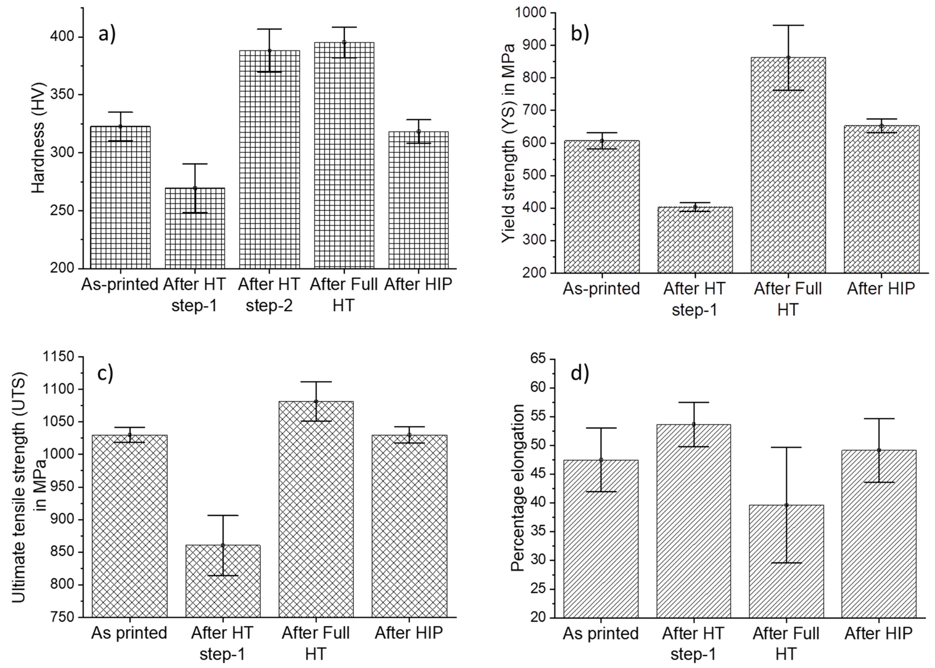
3.3. Mechanical Properties

Figure 7a shows the hardness data after each heat-treatment step. The hardness after the first heat-treatment step significantly decreases. The higher hardness of as-printed samples can be attributed to two major factors. First factor is the presence of dendritic phases as seen in Figure 1a, which inhibit dislocation motion thereby resisting deformation and the second factor is inherently high dislocation density in as-printed samples due to thermal stresses caused by repeated cyclic heating and rapid cooling as seen in Figure 2a. The high dislocation density results in dislocation entanglement, which prevents deformation during indenting. After the first heat-treatment step, the dendritic phases are dissolved and the prolonged exposure to high temperature also reduces the dislocation density in the material, as seen in Figure 2b. Both these factors result in a decreased hardness after first heat-treatment step. Decrease in dislocation density and dissolution of dendritic phases is also manifested in a decrease in yield strength (YS) and ultimate tensile strength (UTS) and increase in elongation as is evident in Figure 7b,c,d respectively.
The second heat-treatment step results in the precipitation of high-volume fraction of γ′-phase. A significant increase in hardness is observed due to this. As mentioned in the earlier sections, since the size of γ′ particles is lesser than doro, the motion of dislocations can happen only by particle shearing. To shear a γ′ particle, a dislocation travelling in γ phase can enter only by forming an anti-phase boundary (APB) at the γ/ γ′ interface. The formation of this APB requires energy, which is the main strengthening mechanism in this case. In the 3rd step, the slight coarsening of γ′ particles reported in the earlier section does not have a significant difference on the hardness and other mechanical properties. The strengthening effect of γ′ phase is also evident in the yield strength and ultimate tensile strength plots shown in Figure 7b,c, respectively. The obstruction to dislocation motion results in reduced elongation during tensile tests of samples after 3rd heat-treatment as seen in Figure 7d.
HIP of as-printed samples also resulted in the precipitation of γ′-phase. But the potential increase in hardness and strength due to this appears to have been offset by the significant increase in the grain size post-HIP. Increase in grain size increases the mean-free path of dislocations causing increased deformation during indentation and tensile tests, and hence results in reduced hardness and strength according to the Hall–Petch equation. Although the hardness, yield strength, and ultimate tensile strength at room temperature of the as-printed and HIPed samples is similar, the high temperature properties and fatigue strength of HIPed samples will be higher than that of the as-printed samples due to the presence of γ′ phase in the HIPed samples.

4. Conclusions

In this work, correlations have been developed and reported between post-processing route, microstructure, and mechanical properties and analyzes the effect of different heat-treatment routes on Haynes-282 processed with SLM. The strengthening γ′-phase is observed only after the second heat-treatment step, while HIP treatment precipitates γ′-phase in one single step. In-situ study of precipitate evolution shows rapid growth to ~130 nm followed by sluggish coarsening. Aging heat-treatment applied based on the results of in-situ heat-treatment, resulted in enhanced mechanical properties due to high volume fraction of γ′-phase. Further aging does not result in significant γ′ coarsening and hence no substantial effect on mechanical properties is observed due to further aging. Microstructure after HIP treatment of Haynes-282 processed with SLM, reported for the first time in the literature, shows considerable recrystallization and formation of annealing twins. Coarsening of grains resulted in mechanical properties comparable to those of as-printed samples despite the presence of γ′-phase in the HIPed samples.

Author Contributions

Conceptualization, A.D. and K.H.; methodology, A.D. and S.D.N.; formal analysis, A.D. and K.H.; resources, K.H. and S.A.; writing—original draft preparation, A.D.; writing—review and editing, A.D. and K.H.; supervision, K.H. and S.A.; All authors have read and agreed to the published version of the manuscript.

Funding

This research received no external funding.

Conflicts of Interest

The authors declare no conflict of interest.

References

  1. Raghavan, S.; Raghavan, S.; Zhang, B.; Wang, P.; Sun, C.-N.; Nai, M.L.S.; Li, T.; Wei, J. Effect of different heat treatments on the microstructure and mechanical properties in selective laser melted INCONEL 718 alloy. Mater. Manuf. Process. 2017, 32, 1588–1595. [Google Scholar] [CrossRef]
  2. Amato, K.; Gaytan, S.M.; Murr, L.E.; Martinez, E.; Shindo, P.W.; Hernandez, J.; Collins, S.; Medina, F. Microstructures and mechanical behavior of Inconel 718 fabricated by selective laser melting. Acta Mater. 2012, 60, 2229–2239. [Google Scholar] [CrossRef]
  3. Li, C.; White, R.; Fang, X.; Weaver, M.; Guo, Y. Microstructure evolution characteristics of Inconel 625 alloy from selective laser melting to heat treatment. Mater. Sci. Eng. A 2017, 705, 20–31. [Google Scholar] [CrossRef]
  4. Li, S.; Wei, Q.; Shi, Y.; Zhu, Z.; Zhang, D. Microstructure characteristics of Inconel 625 superalloy manufactured by selective laser melting. J. Mater. Sci. Technol. 2015, 31, 946–952. [Google Scholar] [CrossRef]
  5. Tomus, D.; Tian, Y.; Rometsch, P.A.; Heilmaier, M.; Wu, X. Influence of post heat treatments on anisotropy of mechanical behaviour and microstructure of Hastelloy-X parts produced by selective laser melting. Mater. Sci. Eng. A 2016, 667, 42–53. [Google Scholar] [CrossRef]
  6. Vilaro, T.; Colin, C.; Bartout, J.-D.; Nazé, L.; Sennour, M. Microstructural and mechanical approaches of the selective laser melting process applied to a nickel-base superalloy. Mater. Sci. Eng. A 2012, 534, 446–451. [Google Scholar] [CrossRef]
  7. Seetharaman, S.; Krishnan, M.; Wen, F.G.C.; Khan, N.A.; Lai, G.N.K. Research updates on the additive manufacturing of nickel based superalloys. In Proceedings of the Solid Freeform Fabrication 2016: Proceedings of the 27th Annual International Solid Freeform Fabrication Symposium, Austin, TX, USA, 8–10 August 2016; pp. 486–496. [Google Scholar]
  8. Xiao, H.; Li, S.M.; Xiao, W.J.; Li, Y.Q.; Cha, L.M.; Mazumder, J.; Song, L.J. Effects of laser modes on Nb segregation and Laves phase formation during laser additive manufacturing of nickel-based superalloy. Mater. Lett. 2017, 188, 260–262. [Google Scholar] [CrossRef]
  9. Wang, X.; Chou, K. Effects of thermal cycles on the microstructure evolution of Inconel 718 during selective laser melting process. Addit. Manuf. 2017, 18, 1–14. [Google Scholar] [CrossRef]
  10. Zhong, M.; Sun, H.; Liu, W.; Zhu, X.; He, J. Boundary liquation and interface cracking characterization in laser deposition of Inconel 738 on directionally solidified Ni-based superalloy. Scr. Mater. 2005, 53, 159–164. [Google Scholar] [CrossRef]
  11. Aydinöz, M.; Brenne, F.; Schaper, M.; Schaak, C.; Tillmann, W.; Nellesen, J.; Niendorf, T. On the microstructural and mechanical properties of post-treated additively manufactured Inconel 718 superalloy under quasi-static and cyclic loading. Mater. Sci. Eng. A 2016, 669, 246–258. [Google Scholar] [CrossRef]
  12. Zhang, D.; Niu, W.; Cao, X.; Liu, Z. Effect of standard heat treatment on the microstructure and mechanical properties of selective laser melting manufactured Inconel 718 superalloy. Mater. Sci. Eng. A 2015, 644, 32–40. [Google Scholar] [CrossRef]
  13. Zhao, X.; Lin, X.; Chen, J.; Xue, L.; Huang, W. The effect of hot isostatic pressing on crack healing, microstructure, mechanical properties of Rene88DT superalloy prepared by laser solid forming. Mater. Sci. Eng. A 2009, 504, 129–134. [Google Scholar] [CrossRef]
  14. Han, Q.; Mertens, R.; Montero-Sistiaga, M.L.; Yang, S.; Setchi, R.; Vanmeensel, K.; Van Hooreweder, B.; Evans, S.L.; Fan, H. Laser powder bed fusion of Hastelloy X: Effects of hot isostatic pressing and the hot cracking mechanism. Mater. Sci. Eng. A 2018, 732, 228–239. [Google Scholar] [CrossRef]
  15. Kreitcberg, A.; Brailovski, V.; Turenne, S. Effect of heat treatment and hot isostatic pressing on the microstructure and mechanical properties of Inconel 625 alloy processed by laser powder bed fusion. Mater. Sci. Eng. A 2017, 689, 1–10. [Google Scholar] [CrossRef]
  16. Joseph, C.; Persson, C.; Colliander, M.H. Influence of heat treatment on the microstructure and tensile properties of Ni-base superalloy Haynes 282. Mater. Sci. Eng. A 2017, 679, 520–530. [Google Scholar] [CrossRef] [Green Version]
  17. Reed, R.C. The Superalloys: Fundamentals and Applications; Cambridge University Press: Cambridge, UK, 2008. [Google Scholar]
  18. Pike, L. Long term thermal exposure of Haynes 282 alloy. In Proceedings of the 7th International Symposium on Superalloy, Pittsburgh, PA, USA, 10–13 October 2010; Volume 718, pp. 645–660. [Google Scholar]
  19. Pike, L. HAYNES® 282TM alloy: A new wrought superalloy designed for improved creep strength and fabricability. In ASME Turbo Expo 2006: Power for Land, Sea, and Air; American Society of Mechanical Engineers Digital Collection: New York, NY, USA, 2006; pp. 1031–1039. [Google Scholar]
  20. Matysiak, H.; Zagorska, M.; Andersson, J.; Balkowiec, A.; Cygan, R.; Rasinski, M.; Pisarek, M.; Andrzejczuk, M.; Kubiak, K.; Kurzydlowski, K.J. Microstructure of Haynes® 282® superalloy after vacuum induction melting and investment casting of thin-walled components. Materials 2013, 6, 5016–5037. [Google Scholar] [CrossRef] [Green Version]
  21. Ramakrishnan, A.; Dinda, G. Microstructure and mechanical properties of direct laser metal deposited Haynes 282 superalloy. Mater. Sci. Eng. A 2019, 748, 347–356. [Google Scholar] [CrossRef]
  22. Cao, Y.; Bai, P.; Liu, F.; Hou, X. Investigation on the precipitates of IN718 alloy fabricated by selective laser melting. Metals 2019, 9, 1128. [Google Scholar] [CrossRef] [Green Version]
  23. Sui, S.; Chen, J.; Fan, E.; Yang, H.; Lin, X.; Huang, W. The influence of Laves phases on the high-cycle fatigue behavior of laser additive manufactured Inconel 718. Mater. Sci. Eng. A 2017, 695, 6–13. [Google Scholar] [CrossRef]
  24. Bi, G.; Sun, C.-N.; Chen, H.-C.; Ng, F.L.; Ma, C.C.K. Microstructure and tensile properties of superalloy IN100 fabricated by micro-laser aided additive manufacturing. Mater. Des. 2014, 60, 401–408. [Google Scholar] [CrossRef]
  25. Osoba, L.; Ding, R.; Ojo, O. Microstructural analysis of laser weld fusion zone in Haynes 282 superalloy. Mater. Charact. 2012, 65, 93–99. [Google Scholar] [CrossRef]
  26. Meher, S.; Rojhirunsakool, T.; Hwang, J.; Nag, S.; Tiley, J.; Banerjee, R. Coarsening behaviour of gamma prime precipitates and concurrent transitions in the interface width in Ni-14 at.% Al-7 at.% Cr. Philos. Mag. Lett. 2013, 93, 521–530. [Google Scholar] [CrossRef]
  27. Maheshwari, A.; Ardell, A. Anomalous coarsening behavior of small volume fractions of Ni3Al precipitates in binary Ni-Al alloys. Acta Metall. Mater. 1992, 40, 2661–2667. [Google Scholar] [CrossRef]
  28. Klepser, C. Effect of continuous cooling rate on the precipitation of gamma prime in nickel-based superalloys. Scr. Metall. Mater. 1995, 33. [Google Scholar] [CrossRef]
  29. Kim, H.; Chun, S.; Yao, X.; Fang, Y.; Choi, J. Gamma prime (γ′) precipitating and ageing behaviours in two newly developed nickel-base superalloys. J. Mater. Sci. 1997, 32, 4917–4923. [Google Scholar] [CrossRef]
  30. Xu, R. The effect of high pressure on solidification microstructure of Al–Ni–Y alloy. Mater. Lett. 2005, 59, 2818–2820. [Google Scholar] [CrossRef]
  31. Lopez-Galilea, I.; Huth, S.; Bartsch, M.; Theisen, W. Effect of HIP parameters on the micro-structural evolution of a single crystal Ni-based superalloy. Adv. Mater. Res. 2011, 278, 72–77. [Google Scholar] [CrossRef] [Green Version]
  32. Antonysamy, A.A.; Meyer, J.; Prangnell, P. Effect of build geometry on the β-grain structure and texture in additive manufacture of Ti6Al4V by selective electron beam melting. Mater. Charact. 2013, 84, 153–168. [Google Scholar] [CrossRef]
  33. Mostafa, A.; Picazo Rubio, I.; Brailovski, V.; Jahazi, M.; Medraj, M. Structure, texture and phases in 3D printed IN718 alloy subjected to homogenization and HIP treatments. Metals 2017, 7, 196. [Google Scholar] [CrossRef] [Green Version]
  34. Pham, M.; Dovgyy, B.; Hooper, P. Twinning induced plasticity in austenitic stainless steel 316L made by additive manufacturing. Mater. Sci. Eng. A 2017, 704, 102–111. [Google Scholar] [CrossRef]
  35. Ni, M.; Chen, C.; Wang, X.; Wang, P.; Li, R.; Zhang, X.; Zhou, K. Anisotropic tensile behavior of in situ precipitation strengthened Inconel 718 fabricated by additive manufacturing. Mater. Sci. Eng. A 2017, 701, 344–351. [Google Scholar] [CrossRef]
  36. Dudova, N.; Belyakov, A.; Sakai, T.; Kaibyshev, R. Dynamic recrystallization mechanisms operating in a Ni–20% Cr alloy under hot-to-warm working. Acta Mater. 2010, 58, 3624–3632. [Google Scholar] [CrossRef]
  37. Chen, X.-M.; Lin, Y.; Wu, F. EBSD study of grain growth behavior and annealing twin evolution after full recrystallization in a nickel-based superalloy. J. Alloys Compd. 2017, 724, 198–207. [Google Scholar] [CrossRef]
  38. Wang, M.; Sun, C.; Fu, M.; Liu, Z.; Wang, C. Microstructure and microtexture evolution of dynamic recrystallization during hot deformation of a nickel-based superalloy. Mater. Des. 2020, 188, 108429. [Google Scholar] [CrossRef]
  39. Pataky, G.J.; Sehitoglu, H.; Maier, H.J. High temperature fatigue crack growth of Haynes 230. Mater. Charact. 2013, 75, 69–78. [Google Scholar] [CrossRef]
Figure 1. (a) Optical image of as-printed microstructure of Haynes-282, (b) SEM image of an as-printed microstructure of Haynes-282. The dendritic segregation is clearly seen in the SEM image. (c) Optical image of microstructure after solutionizing step (or heat-treatment step-1) and (d) SEM image of microstructure after solutionizing step.
Metals 10 00629 g001
Figure 2. (a) Bright field TEM image of the as-printed sample. High dislocation density is clearly evident, (b) TEM bright field image after solutionizing step.
Metals 10 00629 g002
Figure 3. (a) Bright field TEM image after first heat-treatment step and before the start of in-situ heating, (b) bright field TEM image when the temperature of the sample has reached 950 °C, (c) diffraction pattern before the start of in-situ heating, and (d) diffraction pattern when the sample has reached 950 °C.
Metals 10 00629 g003
Figure 4. (a) Optical image of the microstructure after 2nd heat-treatment step, (b) SEM image of the microstructure after 2nd heat-treatment step, (c) Optical image of the microstructure after 3rd and final heat-treatment step, and (d) SEM image of the microstructure after 3rd and final heat-treatment step.
Metals 10 00629 g004
Figure 5. (a) SEM image of microstructure after hot isostatic pressing (HIP) showing grain boundary carbides, (b) SEM image taken at a higher magnification to show γ′ precipitation after HIP treatment.
Metals 10 00629 g005
Figure 6. Electron backscatter diffraction (EBSD) inverse pole figures of samples (a) as-printed, (b) after 1st heat-treatment, (c) after 2nd heat-treatment step, (d) after full heat-treatment (or 3rd step), and (e) After HIP treatment.
Metals 10 00629 g006
Figure 7. (a) Hardness values after every heat-treatment step; (b) yield strength of samples as-printed, after full heat-treatment, and after HIP; (c) ultimate tensile strength (UTS) of samples as-printed, after full heat-treatment, and after HIP; and (d) percentage elongation of samples as-printed, after full heat-treatment, and after HIP.
Metals 10 00629 g007
Table 1. Table showing the powder size distribution of the Haynes-282 powder as-received from the manufacturer.
D10 (μm)D50 (μm)D90 (μm)
18.929.344.3
Table 2. Table showing the composition in weight percentage of the Haynes-282 powder as-received from the manufacturer.
NiCrCoMoTiAlFeMnSiCBONPS
58.48419.210.38.32.11.52000.020.050.0050.0070.005<0.0050.004
Table 3. Table showing optimized process parameters used to print test cubes and tensile test coupons.
Laser Power (W)Speed (mm/s)Hatch Spacing (mm)Layer Thickness (mm)Energy Density (J/m3)
756500.0770.0275
Table 4. Table with details of the heat treatment parameters used.
MethodStep 1Step 2Step 3
Heat treatment1120 °C/2 h/water quench1000 °C/2 h/Furnace cooling788 °C/8 h/Furnace cooling
Hot isostatic processing (HIP)1185 °C/150MPa/3.5 h

