Article

Microstructural and Mechanical Characterization of a Nanostructured Bainitic Cast Steel

by
Andrés Felipe Santacruz-Londoño
1,
Oscar Rios-Diez
1,
José A. Jiménez
2,
Carlos Garcia-Mateo
2,* and
Ricardo Aristizábal-Sierra
1,*
1
Gipimme, Department of Materials Engineering, Engineering Faculty, Universidad de Antioquia, Calle 67 #53-108, Bloque 18, Oficina 240, Medellín 050010, Colombia
2
Department of Physical Metallurgy, National Center for Metallurgical Research (CENIM-CSIC), Avenida Gregorio del Amo, 8, 28040 Madrid, Spain
*
Authors to whom correspondence should be addressed.
Metals 2020, 10(5), 612; https://doi.org/10.3390/met10050612
Submission received: 15 April 2020 / Revised: 4 May 2020 / Accepted: 6 May 2020 / Published: 8 May 2020
(This article belongs to the Special Issue Advanced Multiphase Steels)

Abstract

:
Nanoscale bainite is a remarkable microstructure that exhibits a very promising combination of high strength with good ductility and toughness. The development of these types of microstructures has been focused on wrought materials, and very little information is available for steel castings. In this work, a specially designed cast steel with 0.76 wt % C was fabricated, and the heat treatment cycles to develop bainitic nanostructures were determined by studying the kinetics of the bainitic transformation using high-resolution dilatometry. The effects of isothermal holding temperature and time on the final microstructure and mechanical properties were thoroughly characterized in order to evaluate a future industrial implementation of the process in an effort to contribute to enhance and widen the potential applications for cast steels.

1. Introduction

Nanoscale bainite is an outstanding microstructure that exhibits a very promising combination of mechanical properties [1,2,3,4,5,6]. This microstructure is usually obtained by isothermal heat treatment above the martensite start temperature, Ms, in steels that must contain at least 1.5 mass %Si, which is an element indispensable if the precipitation of carbides during the bainitic reaction is to be avoided. The final microstructure thus obtained is an elegant mixture of interwoven plates of bainitic ferrite (αb) and thin films of C-enriched retained austenite (γf), both with tens of nm in thickness [7].
As bainitic transformation has a displacive nature, one of the most efficient ways of controlling the size scale of the final microstructure is by increasing the strength of the parent austenite. This is achieved by increasing the C concentration [8], alloying with strong austenite solid solution strengtheners, as Mn, Si, and Cr, as well as allowing for the transformation to take place at the lowest possible temperatures, between Ms and the bainite start temperatures, Bs [7,8]. By following these concepts, the strength of the final bainitic microstructure can be controlled and improved.
During the last couple of decades, the vast majority of the research on the development of nanoscale bainitic microstructures in steels has been focused on wrought materials [9,10,11,12,13]. For example, in steels with 0.7–1.0 wt % C, nanosized structures consisting of a matrix of bainitic plates with 20–40 nm in size separated by slightly thicker films of C-enriched retained austenite have been produced using an isothermal treatment of several hours at temperatures around 200 °C [9,14,15,16,17]. This microstructure confers to steels high ultimate tensile strengths, UTS, above 2.0 GPa, high yield strength, YS, above 1.5 GPa, accompanied by very reasonable ductility, 5–20% total elongation, and good fracture toughness 45–90 MPa/m1/2 [14,16,18,19]. More recently, such microstructures are gaining interest as substitutes for conventional alloys in applications where good rolling/sliding wear is required, outperforming conventional alloys and microstructures [20,21], with better hardenability and lower production costs [11,17]. Therefore, nowadays, they have potential applications in the railway, defense, and mining industries, among others.
A wider niche of applications is foreseen if the same microstructural concept is transferred to cast steels, which are extensively used in applications where obtaining near finished or finished parts with complex geometries, and these geometries cannot be achieved easily by plastic deformation such as rolling or forging, which is a limitation. The closest and few studies related to the subject deal with high-silicon bainitic steels, which are commonly called austempered high-silicon cast steels [22,23,24,25,26].
In the 1990s, Voigt et al. published one of the first and most complete research studies about austempered high-silicon cast steels containing 0.6–1.2 C and 1.4–2.4 Si in wt %. After an isothermal heat treatment at temperatures ranging from 320 to 400 °C for 0.5 to 10 h, they have studied their mechanical behavior by tensile, impact, and wear testing. They found that depending on the chemical composition and temperature, these treatments can provide high wear resistance together with UTS between 1.0 and 1.6 GPa, YS between 0.7 and 1.3 GPa, elongation to failure between 7% and 20% and impact toughness between 6 and 28 J [22]. A few years later, Putatunda evaluated the effect of the austenitizing temperature on the mechanical properties of an austempered high C, high Si, high Mn cast steel. He found lower values for both UTS (600–800 MPa) and elongation to failure (up to 1.5%) were associated with the presence of graphite nodules within the microstructure [23]. In order to refine the grain size of high-silicon austempered cast steel, Chen et al. included vanadium and titanium in the alloy. After an isothermal treatment for 1 h at several temperatures, they reported UTS and YS as high as 2.1 GPa and 1.8 GPa, respectively [24]. Finally, Son et al. have reported for austempered high-silicon cast steels (0.9 C-2.3 Si-0.3 Mn all in wt %) values for the UTS ranging from 1.4 to 2.2 GPa and elongation to failure between 25% and 5% after isothermal heat treatments at temperatures between 240 and 400 °C for 0.5 to 2 h [25].
Another important issue, not yet addressed, is the stability of the microstructure and its mechanical response when isothermal treatments are performed for times longer than strictly necessary. Due to the continuous character of the feeding process, this situation can be common when austenitized samples are transferred to the isothermal baths, where there are pieces that would withstand longer times than intended.
In summary, the reviewed research still only offers a limited picture on the microstructural and mechanical characterization of nanostructured bainitic cast steels. This work is aimed to offer more data on the microstructural characterization of a cast steel of composition (in wt %) 0.76C–2.08Si–0.74Mn–0.79Cr after isothermal treatments that leads to the bainitic transformation. The effect of holding temperature and time on the microstructure and mechanical properties were evaluated to advance the development of nanobainitic microstructure in these materials for future industrial applications.

2. Materials and Methods

The alloy for this study was obtained in a 50 KW induction furnace at the casting laboratory of the Universidad de Antioquia, Medellin-Colombia. Low-carbon steel scrap, low-sulfur graphite, ferrosilicon, and ferrochromium were used to prepare the alloy. After melting, the steel was deoxidized with 0.1 wt % Al and poured at 1600–1620 °C into chemical bonded silica sand molds to obtain Y-blocks that were 25 mm thick. The final chemical composition of the alloy determined by optical emission spectroscopy (OES) using a Bruker Q8 Magellan (Bruker, Karlsruhe, Germany) was (in wt %) 0.76C-2.08Si-0.74Mn-0.79Cr. This material has high C and more than 1.5 wt % Si to increase the strength of the parent austenite and to promote the development of a carbide-free nanoscale microstructure composed mainly by a bainitic ferrite matrix and retained austenite, during bainitic transformation at low isothermal temperatures. Finally, Mn and Cr were added to further increase the solid solution strengthening of the parent austenite and to provide the alloy with enough hardenability. After shaking out, the cast steel was homogenized at 1100 °C during 48 h in vacuum.
A BAHR 805A high-resolution dilatometer (TA Instruments, Wetzlar, Germany) was used to determine the heat treatment parameters and to study the kinetics of the bainitic transformation in cylindrical specimens with 4 mm diameter and 10 mm length, which were machined from the homogenized alloy. This equipment uses an induction heating coil and blowing He to control the temperature during the test with the help of a type K thermocouple welded to the central part of the sample surface. The longitudinal changes in length during the thermal cycle were measured by fused silica push-rods in direct contact with the sample. Two set of experiments were performed to achieve the objective of this work: firstly, it the critical processing temperatures Ac1 and Ac3 were determined as in ref. [27] and the Ms temperature was determined as in ref [28]. The Bs temperature was calculated according with ref. [29]. A second set of experiments, after determination of the optimal heat treatment conditions, allowed studying the kinetics of the bainitic transformation at different isothermal temperatures, Tiso, from where the end of the bainitic transformation, tf, was determined as described in ref. [30] with a threshold of zero.
Tensile and impact toughness (Charpy V-notch) specimens of the cast steel were cut and machined by a computer numerical control machine, according to the standard ASTM [31,32]. Then, the specimens were thermally treated, together with a coupon sample for microstructural characterization in order to develop the desired microstructures, following the parameters given later in this paper. Austenitization performed in vacuum with an electrical furnace was followed by immersion in isothermal salt baths (50% NaNO2 + 50% KNO3) at temperatures selected for the bainitic transformation.
A tension test was carried out at room temperature using an INSTRON 5984 machine with 150 kN (Instron, Germany) loading capacity and a cross-head speed of 3 s−1. An extensometer set to a gauge length of 25 mm was used for strain measurement in 6 mm thick rectangular subsized specimens. At least three specimens were tested for each condition, and the average and standard deviation were calculated. True stress, σ t , and true strain, ε t , data were used to calculate the incremental work hardening exponent, n = d l o g ( σ t ) / d l o g ( ε t ) , during the tensile test as a function of ε t for each heat treatment condition. Impact toughness was evaluated by using a Karl Frank GMBH-300J Charpy testing machine (Karl Frank GmbH, Weinheim-Birkenau, Germany), at room temperature; three V-notch specimens were tested for each heat treatment condition. Rockwell C Hardness measurements were made using a Harterprufer-Swiss MAX 300 hardness testing machine (Gnehm Härteprüfer AG, Thalwil, Switzerland), at least five indents were made on each sample, and the average values were taken.
Specimens for microstructural characterization were sectioned and polished following a conventional metallographic technique, and the microstructure was revealed by etching with Nital 2%. The revealed microstructure was analyzed with an optical and a scanning electron microscope –SEM- (Nikon M100 from Niko Instrument Inc, Melville, NY, USA and JEOL-JSM 6490LV, from JEOL Ltd, Tokyo, Japan, respectively). For each of the tested conditions, the methodology described in refs. [33,34] was used to determine the thickness of bainitic ferrite and the size of retained austenite from SEM images.
Microstructural evolution during isothermal treatments was also followed by X-ray diffraction (XRD) measurements conducted with Co Kα radiation (λ = 1.78901 Å) in a Panalytical Empyrean 2012 (PANanalytical B.V., Almelo, The Netherland) diffractometer working at 40 KV and 100 mA. Conventional θ–2θ scans were performed over 2θ ranging from 30° to 110° at a rate of 0.6 min−1. XRD sample preparation included conventional metallographic techniques, followed by a final set of cycles of etching and polishing to remove the plastically deformed surface layer introduced during the grinding step.
Quantitative phase analysis from XRD patterns was performed with the version 4.2 of the Rietveld analysis program DIFFRACplus TOPAS (Bruker AXS GmbH, Karlsruhe, Germany) and the crystallographic information of ferrite and austenite. Besides, this refinement included explicitly other microstructural parameters such as lattice parameters, crystallite size, and microstrain. As the unit-cell parameters of austenite are defined by the amount of carbon in solid solution, the concentration of this element in this phase was calculated using Dyson and Holmes’ equation [35]. Finally, the crystallite size, D, and lattice strain, ε, were determined simultaneously from line broadening using the double Voigt approach [36]. For this analysis, the instrumental contribution to peak broadening was removed using the diffraction pattern of a LaB6 standard. It must be pointed out that the value of the domain size and strain parameters calculated from this procedure present large standard deviations (up to 20%).

3. Results and Analysis

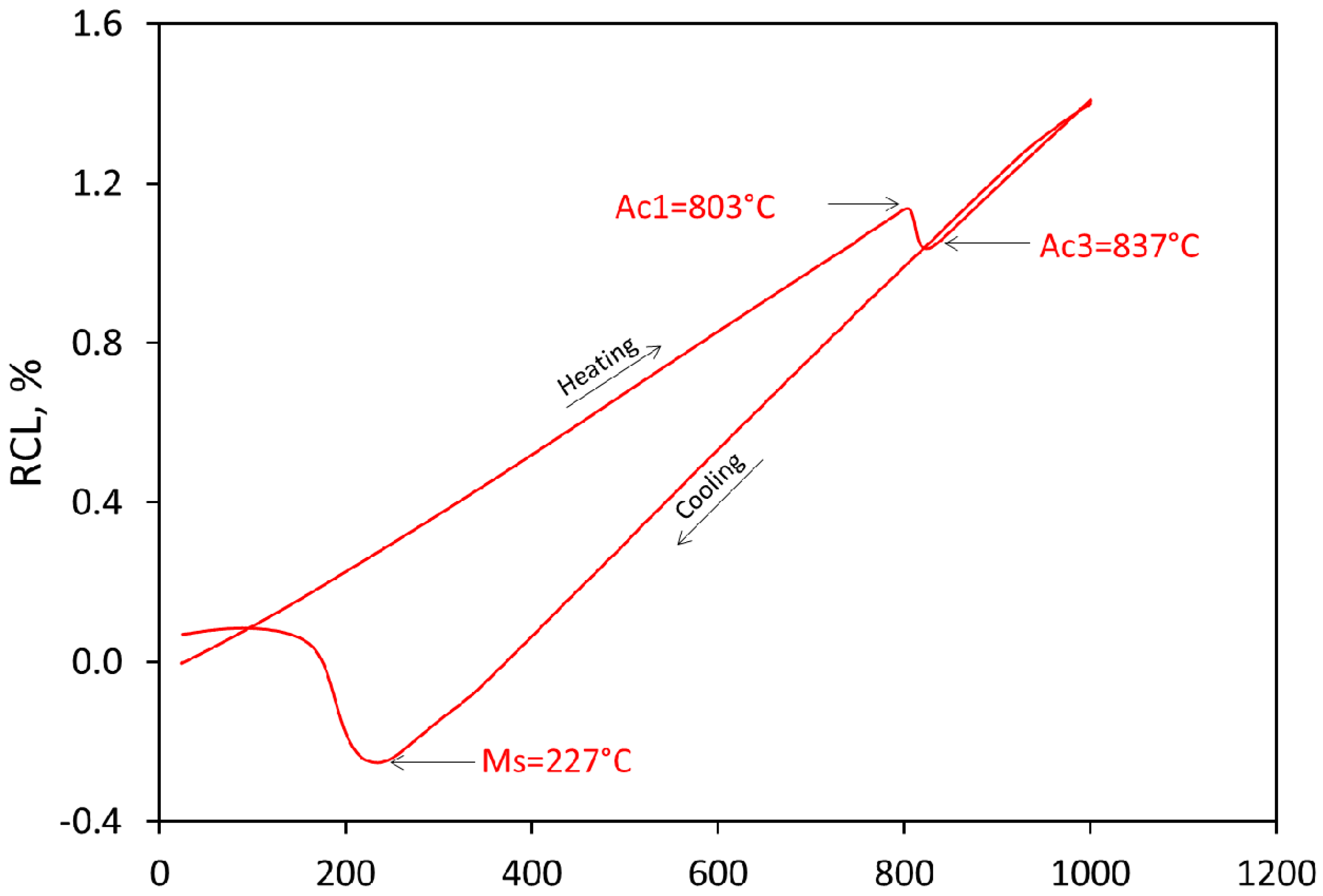
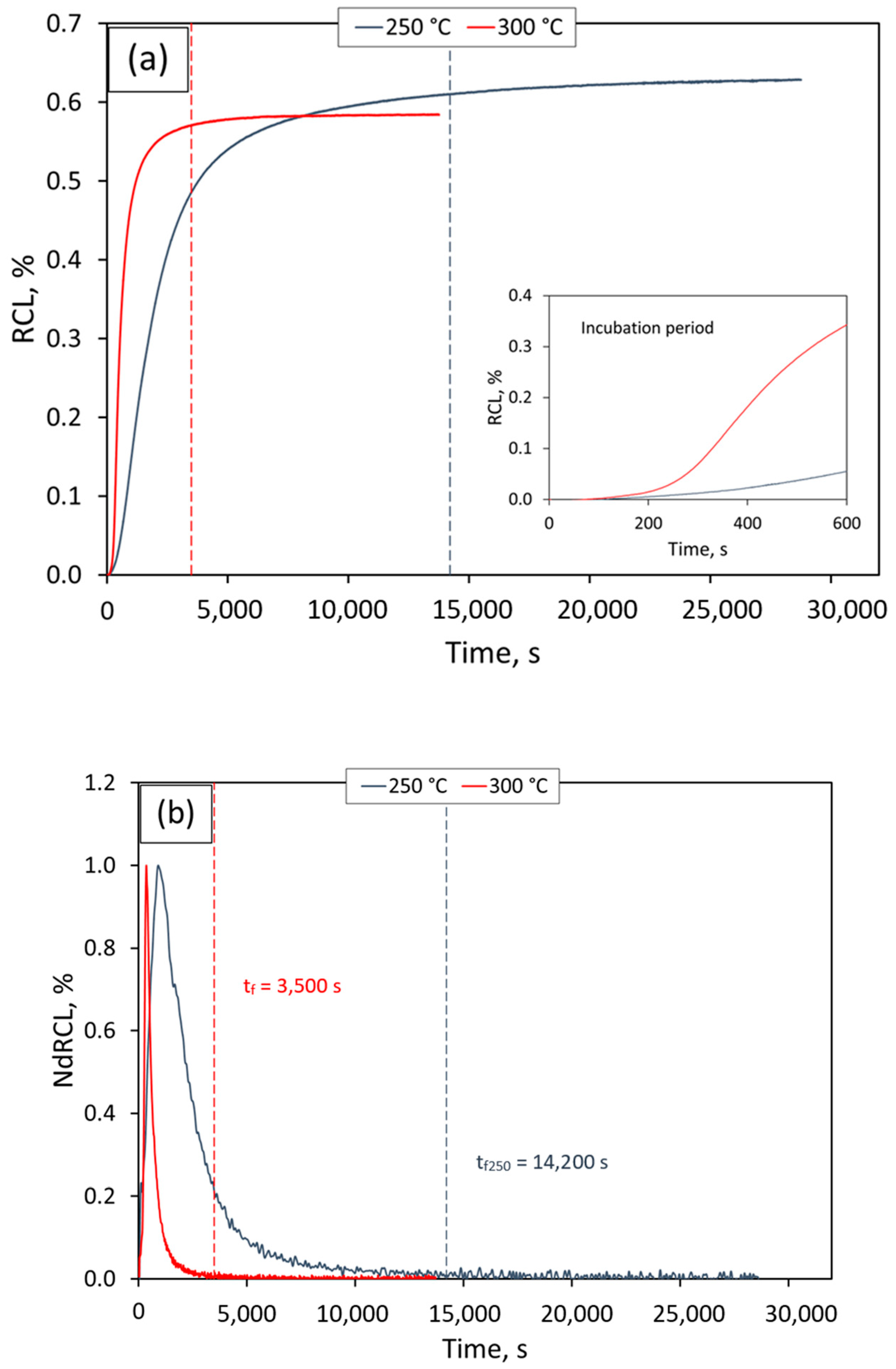
3.1. Establishing Heat Treatment Conditions

A first set of dilatometric measurements using specific heating and cooling rates, determined from previous experiences in steels with similar compositions [11,15,17], were performed to obtain the critical transformation temperatures and to establish the austenitizing conditions and cooling rate to Tiso. Figure 1 shows the relative change in length (RCL) of the dilatometric sample as a function of temperature, during a thermal cycle that consisted of heating at 5 °C/s to 1000 °C, holding for 10 min, and cooling down at 35 °C/s to room temperature. From this figure, we determined values of 803 and 837 °C for Ac1 and Ac3, respectively. Notice that during cooling from the austenitization temperature, only the beginning of the martensitic transformation was detected at 227 °C. The absence of changes on the cooling curve before this temperature indicates that no intermediate transformations that can interfere with the bainitic reaction can take place at the chosen cooling rate. Additionally, the Bs temperature was calculated as 447 °C using the equation given in ref. [29].
An austenitization T-t of 900 °C for 10 min followed by cooling at 35 °C/s down to Tiso were selected for the study of the bainitic transformation considering the previous results. The chosen Tiso (Ms < Tiso < Bs) values were 250 and 300 °C, and the holding time was adapted according to previous experiences in wrought steels as 8 and 4 h respectively, to ensure that the transformation finished [11,15,17]. Notice that the selected Tiso values were close to Ms in order to promote the refinement of the microstructure. The RCL curves of Figure 2a show the typical sigmoidal shape, with a first part corresponding to the incubation period, where no transformation takes place or it is undetectable (RCL approximately 0), of 120 and 80 s for the isothermal treatments at 250 and 300 °C, respectively. Then, the curve shows a characteristic steady increase in RCL, which indicates the continuous decomposition of the parent austenite into bainitic ferrite. Finally, a steady state is reached (RLC approximately constant), indicating that no further transformation is occurring. The time for the end of the transformation, tf, must be contained within such a steady region, and it has been determined from the normalized first derivative of RCL curves, NdRCL, as the time where the transformation rate reached a value of zero [30]. Figure 2b shows NdRCL at 250 °C and 300 °C and the corresponding tf at 14,200 and 3500 s, respectively. Vertical dotted lines indicate tf in Figure 2a,b.
The dilatometric results shown in Figure 2 are completely aligned with the displacive and difussionless theory that describes bainitic transformation [7]; i.e., when Tiso decreases, a higher fraction of bainitic ferrite is formed (>RCL), but the kinetic of the transformation is slower. As no martensite was detected on the cooling curve after isothermal transformation under any of the conditions, the expected final microstructure should be composed mainly by bainitic ferrite and dispersed retained austenite.
At this point, it has to be remarked that the obtained results show that the kinetics of the transformation are far faster for the studied cast steel than for similar reported wrought steels in similar treatment conditions, see for example ref. [10]. Although it is not the aim of this paper, it is speculated that such acceleration could be associated with local variations on chemical composition associated to microsegregation during casting solidification, which have been previously reported [37], favoring a fast transformation in certain regions and generating a concomitant catalytic effect on the overall bainitic reaction. In addition, the presence of a greater amount of non-metallic inclusion in cast steels would increase the number of site for the heterogeneous nucleation of bainitic ferrite in other places than austenite grain boundaries [38,39,40,41]. However, further research to explain this issue would be required.
As already mentioned, to test the robustness of the process, two different times were chosen for the isothermal bainitic transformation: one corresponding approximately to tf and the other twice its value (2 × tf). Thus, specimens for microstructural characterization, tensile, and charpy tests were then austenitized at 900 °C during 45 min and isothermally treated according to the parameters given in the next section.

3.2. Microstructural Characterization

Microstructural characterization after isothermal transformation at 250 °C for 4 h (tf) and 8 h (2 × tf) and at 300 °C for 1 h (tf) and 2 h (2 × tf) confirms the dilatometric results previously reported. As shown in Figure 3, the microstructure consist of a bainitic ferrite (αb) matrix that included some films of C-enriched retained austenite (γf). There are also some blocks (γb) of retained austenite (few microns) between the bainitic sheaves. With the characterization techniques used in this work, the presence of cementite has not been detected in any of the studied cases, and as pointed out earlier, its presence should be restricted due to the high Si concentration in the alloy.
A decrease of the holding temperature, Tiso, used for the bainitic transformation produces finer microstructures with a higher volume fraction of bainitic ferrite. Figure 4 shows the distribution histograms of the thickness of bainitic ferrite and the size of retained austenite. The average thickness and size of the phases are included in Figure 4 and show that both isothermal temperatures lead to nanoscale microstructures. The accumulated frequency curves show that in all cases, more than 80% of the bainitic ferrite is thinner than 120 nm and 100% is thinner than 300 nm. Regarding retained austenite, 80% or more is smaller than 120 nm, while less than 4% is larger than 300 nm. Although a higher isothermal temperature should produce coarser bainitic ferrite and austenite plates, these figures does not always show this trend. A limited reliability on the plate thickness of both phases can be inferred from the large standard deviation observed, which may be attributed to the inherent microsegregation present in cast alloys.
The results of the Rietveld refinement performed on XRD patterns obtained after isothermal treatments at 250 and 300 °C are summarized in Table 1. Figure 5 displays the representative XRD peak profile for selected isothermal conditions at 300 °C and 250 °C. The results in Table 1 show that the increase of the holding time beyond that strictly necessary to complete the transformation (2 × tf) has a very limited effect on the final microstructure, as revealed in Figure 3 and Figure 4. On the other hand, we observed a lower amount of αb in the sample treated at 300 °C, which is in agreement with the dilatometric results in Figure 2a previously discussed. As recently reported, bainitic ferrite presents a tetragonal crystal structure that is associated with a higher content of carbon in solid solution than those expected by the paraequilibrium phase boundaries [42]. The c/a ratio of bainitic ferrite is maintained upon the holding time and decreases slightly at 300 °C, which is in accordance with previous results [43]. Table 1 also shows the presence of two populations of austenite characterized by a different C concentration, of which one should correspond to the γb, and the other should correspond to the γf between bainitic ferrite subunits. Although it is expected, according to the bainitic transformation theory, that a higher austenite C enrichment is attained as the treatment temperature is lowered, this is not the case. At 300 °C, it can be seen that the level of enrichment is slightly higher than that obtained at 250 °C. This behavior has been previously observed and has been justified by a greater presence of dislocations at lower temperatures that act as traps for the C atoms that migrate from the C supersaturated ferrite to the austenite [42].
Peak broadening analysis of austenite could be associated only to microstrain for the C poor austenite (γb) and to the crystallite size effects for the C-enriched austenite (γf). As shown in Table 1, the value for microstrain in bainitic ferrite and retained austenite almost is not dependent on the holding time, and they are slightly lower at 300 °C. In addition, the microstrain is larger for austenite, indicating that this phase can accommodate a larger amount of the plastic deformation induced by the bainitic transformation [7]. This table also includes the value of the crystallite size for the austenite films. Although the crystallite size and phase thickness may be equivalent, in low-temperature bainitic microstructures, the structural effect of plastic deformation generated during the transformation, such as the dislocations network, stacking faults and twins, may subdivide the thickness of both austenite and bainitic ferrite into coherent domains smaller in size, which do not induce any observable contrast in SEM or transmission electron microscopy (TEM) observations [33].

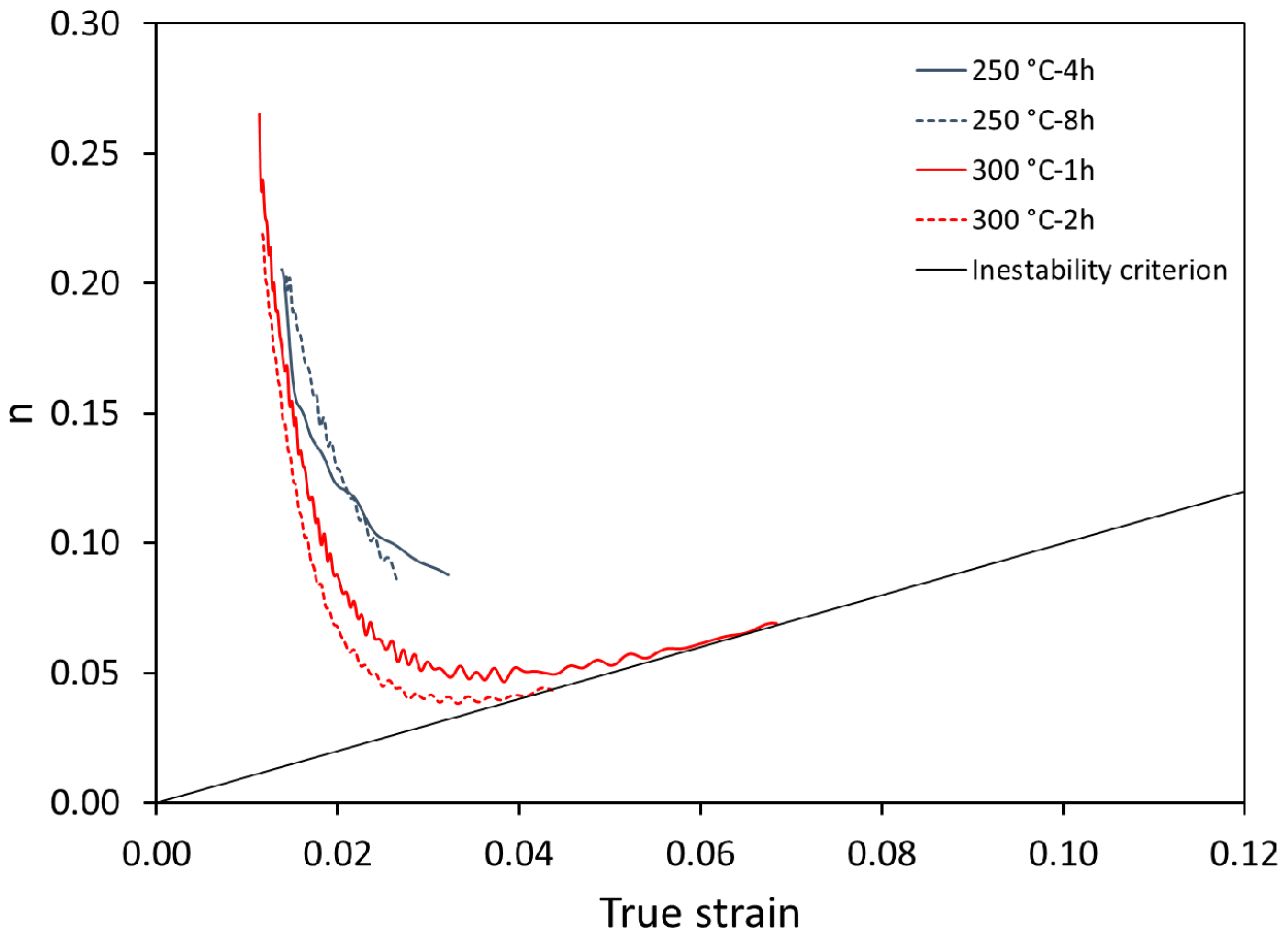
3.3. Mechanical Properties

Table 2 lists hardness, tensile properties, and impact toughness as a function of isothermal heat treatment conditions. Considering the standard deviation associated to these values, it can be concluded that the mechanical properties depend on the isothermal temperature but not on the holding time. This behavior was expected due to the very subtle differences found in the microstructures as the treatment time changed from tf to 2 × tf, highlighting again the robustness of the process. It is evident that a higher fraction of bainitic ferrite and the higher value for the microstain in the austenite observed in Table 1 for the samples treated at 250 °C lead to higher values for HRC, YS, and UTS, but to lower elongation to failure and impact toughness. The higher ductility and impact toughness found in the samples treated at 300 °C is associated to a higher amount of retained austenite with a better capacity of accommodating plastic deformation than bainitic ferrite, as shown in Table 1.
Figure 6 reveals examples of representative engineering stress–strain curves, which are characterized by a continuous yielding typical of microstructures containing mobile dislocations, in this particular case introduced during the isothermal transformation to bainite [7,15,44]. From the same figure, it is also evident that a good portion of plastic deformation is uniformly distributed along the gauge length of the samples, showing little or no necking; in other words, most or all of the total elongation achieved is uniform elongation.
Figure 7 shows the work hardening rate as a function of true strain. According to Considère’s instability criterion, necking in uniaxial tensile test starts when the corresponding true plastic strain is equal to the work hardening exponent, n. As observed in Figure 7, the condition of necking is only reached in the samples isothermally treated at 300 °C, and therefore, the samples treated at 250 °C failed in a brittle way without the onset of necking. For the four conditions tested, it can be observed in Figure 7 that strain-hardening is characterized by a sharp decrease in n, but only in the samples treated at 300 °C was there found an inflection at about 0.03 true strain, which leads to an increase in n up to failure. This work-hardening behavior is common observed in low stacking fault energy (SFE) alloys that exhibit secondary deformation mechanisms such as mechanical twinning or martensitic transformation (transformation or twinning-induced plasticity, TWIP or TRIP effect) [45]. As austenite is often characterized by a low value of SFE, plasticity can be achieved by either of those two deformation mechanisms [46]. When these strain-induced features are preferentially formed during deformation at a certain position of the tensile sample, it produced an intensive local strain hardening of this region that delays the occurrence of the onset of necking and results in larger uniform elongations.
Thus, the higher plasticity found in samples isothermally treated at 300 °C can be effectively argued by the strain-hardening capability of the microstructure, which is twofold, the TRIP effect and the composite-like nature of the microstructures [47]. The TRIP effect, i.e., retained austenite resistance to transform to martensite when subjected to an external mechanical load, is strongly related to its mechanical stability, and intrinsic features of the phase such as the chemical composition, size, and morphology of the features, and the presence of defects in the crystallographic lattice, controls it. It is clear from Table 1 that C in γb is one of the main differences between the 250 and 300 °C microstructures, and it is by far the element with the strongest influence in enhancing the mechanical stability of austenite [48,49,50].
Related to the composite-type nature of the microstructure, properties depending on both the bainitic ferrite matrix and the retained austenite, such as the relative mechanical properties of the phases and the geometry of the composite-type material, have a strong influence on the strain-hardening response, since it influences the way strain/stress partitions between the phases [51,52,53]. It is known that in this type of microstructures, where the bainitic ferrite matrix is harder than the retained austenite [54], a small mechanical mismatch between the phases is also behind the improved ductility [19,20,21,22,23,24,25,26,27,28,29,30,31,32,33,34,35,36,37,38,39,40,41,42,43,44,45,46,47,48,49,50,51,52,53,54,55]. In this particular case, there seems to be, on one hand, a tendency to reduce the strength of the bainitic ferrite as the treatment temperature increases from 250 to 300 °C, which can be justified by a lower C content, i.e., smaller tetragonality, and a lower content of defects, microstrain. On the other hand, the higher observed C content of retained austenite as the treatment temperature increases might contribute to enhance its strength, which becomes closer to the bainitic ferrite values [56].
Finally, it is worth noticing that although the reported YS and impact toughness values in this work fit well with those obtained in similar wrought steels [10,57], the UTS and ductility values are lower, which is most probably due to microsegregation and non-metallic inclusions that can affect the mechanical response. Moreover, the mechanical response of the nanostructured bainite obtained in this study is comparable, or better, than those found in similar austempered high-silicon cast steels, i.e., 0.6-0.9 C-2.3 Si and 0.3 Mo (in wt %) [22] and 0.9 C-2.3 Si and 0.3 Mn (in wt %) [25], which helps understanding the advantage of searching for nanometric structures in bainitic steels (see Figure 8).

4. Conclusions

In this work, it is shown how, in a specially designed cast steel, it has been possible to select the optimum heat treatment parameters to achieve a nano-bainitic microstructure. The microstructures obtained at the two selected low isothermal temperatures are essentially identical to those widely characterized in wrought steels, and the differences in properties that have been detected could be explained in terms of the inherent microsegregation of castings. Moreover, in the forecast of future industrial implementations of this type of heat treatment in cast steels, the robustness of the microstructure and its properties, when submitted to a treatment twice as long as that strictly necessary has been evaluated, and it can be concluded that the extension of the treatment has not introduced significant changes.

Author Contributions

Conceptualization, A.F.S.-L., C.G.-M., and R.A.-S.; Investigation, A.F.S.-L. and O.R.-D.; Project administration, R.A.-S.; Supervision, J.A.J., C.G.-M. and R.A.-S.; Writing—original draft, A.F.S.-L., O.R.-D.; J.A.J., C.G.-M., and R.A.-S.; Writing—review and editing, A.F.S.-L., O.R.-D., J.A.J., C.G.-M., and R.A.-S. All authors have read and agreed to the published version of the manuscript.

Funding

This research received no external funding.

Acknowledgments

The authors want to acknowledge the CENIM (National Center for Metallurgical Research-Madrid-Spain) and the Casting Laboratory of the Universidad de Antioquia in Medellín Colombia.

Conflicts of Interest

The authors declare no conflict of interest.

References

  1. Folgarait, P.; Saccocco, A.; De Ro, A.; Eisenkolb, B. Bainitic steels for new rail materials; Publications Office of the EU: Luxemburg, 2006; ISSN 1018-5593.
  2. Caballero, F.; Santofimia, M.; Capdevila, C.; Garcia de Andres, C.; Zajac, S.; Allain, S.; Iung, T.; Couturier, A.; Drillet, J.; Quidort, D.; et al. Novel high strength, high toughness carbide-free bainitic steels. In Technical Steel Research Publications; Publications Office of the EU: Luxembourg, 2007; p. 137, ISSN 1018-5593. [Google Scholar]
  3. Caballero, F.; Garcia-Mateo, C.; Cornide, J.; Allain, S.; Puerta, J.; Crouvizier, M.; Mastrorillo, T.; Jantzen, L.; Vuorinen, E.; Lindgren, L.; et al. New advanced ultra-high strength bainitic steels: Ductility and formability. In Research Found for Coal and Steel, Technical Steel Research; Publications Office of the EU: Luxembourg, 2013; p. 123, ISSN 1831-9424. [Google Scholar]
  4. Sourmail, T.; Smanio, V.; Ziegler, C.; Heuer, V.; Kuntz, M.; Caballero, F.; Garcia-Mateo, C.; Cornide, J.; Elvira, R.; Leiro, A.; et al. Novel nanostructured bainitic steel grades to answer the need for high-performance steel components (Nanobain). In Research Found for Coal and Steel, Technical Steel Research; Publications Office of the EU: Luxembourg, 2013; p. 123, ISSN 1831-9424. [Google Scholar]
  5. Janisch, R.; Rementiera, R.; Caballero, F.; Garcia-Mateo, C.; Danoix, F.; Pizarro-Sanz, R.; Sampath, S.; Morales-Rivas, L.; Sourmail, T.; Kuntz, M.; et al. Understanding basic mechanism to optimize and predict in service properties of nanobainitic steels (MECBAIN). In Research Found for Coal and Steel, Technical Steel Research; Publications Office of the EU: Luxembourg, 2017; p. 167, ISSN 1831-9424. [Google Scholar] [CrossRef]
  6. Pujante, J.; Casellas, D.; Sourmail, T.; Caballero, F.; Rementeria, R.; Soto, A.; Llanos, J.; Vuorinen, E.; Prakash, B.; Hardell, J.; et al. Novel Nano-Structured Bainitic Steels for Enhanced Durability of Wear Resistant Components: Microstructural Optimisation through Simulative Wear and Field Tests (BAINWEAR). In Research Found for Coal and Steel, Technical Steel Research; Publications Office of the EU: Luxembourg, 2019; p. 147, ISSN 1831-9424. [Google Scholar] [CrossRef]
  7. Bhadeshia, H. Bainite in Steels: Theory and Practice; Maney Publishing: Leeds, UK, 2015. [Google Scholar]
  8. Garcia-Mateo, C.; Sourmail, T.; Caballero, F. Bainitic Steel: Nanostructured. In Encycplopedia of Iron Steel and Their Alloys; CRC Press Inc: Boca Raton, FL, USA, 2016; pp. 271–290. [Google Scholar] [CrossRef]
  9. Cornide, J.; Garcia-Mateo, C.; Capdevila, C.; Caballero, F. An assessment of the contributing factors to the nanoscale structural refinement of advanced bainitic steels. J. Alloy. Compd. 2013, 577, S43–S47. [Google Scholar] [CrossRef]
  10. Garcia-Mateo, C.; Caballero, F. Nanocrystalline Bainitic Steels for Industrial Applications. In Nanotechnology for Energy Sustainability; Wiley-VCH: Weinheim, Germany, 2017; pp. 707–724. [Google Scholar] [CrossRef]
  11. Garcia-Mateo, C.; Sourmail, T.; Caballero, F.; Smanio, V.; Kuntz, M.; Ziegler, C.; Leiro, A.; Vuorinen, E.; Elvira, R.; Teeri, T. Nanostructured steel industrialization: Plausible reality. Mater. Sci. Technol. 2014, 30, 1071–1078. [Google Scholar] [CrossRef] [Green Version]
  12. Garcia-Mateo, C.; Caballero, F.; Bhadeshia, H. Development of hard bainite. ISIJ Int. 2003, 43, 1238–1243. [Google Scholar] [CrossRef] [Green Version]
  13. Avishan, B.; Yazdani, S.; Caballero, F.; Wang, T.; Garcia-Mateo, C. Characterization of microstructure and mechanical properties in two different nanostructured bainitic steels. Mater. Sci. Technol. 2015, 31, 1508–1520. [Google Scholar] [CrossRef] [Green Version]
  14. Garcia-Mateo, C.; Caballero, F. Ultra-high-strength bainitic steels. ISIJ Int. 2005, 45, 1736–1740. [Google Scholar] [CrossRef] [Green Version]
  15. Garcia-Mateo, C.; Caballero, F. Advanced High Strength Bainitic Steels. In Comprehensive Materials Processing; Elsevier Ltd: Amsterdam, The Netherland, 2014; Chapter 9; pp. 165–190. [Google Scholar]
  16. Garcia-Mateo, C.; Caballero, F.; Sourmail, T.; Kuntz, M.; Cornide, J.; Smanio, V.; Elvira, R. Tensile behaviour of a nanocrystalline bainitic steel containing 3 wt% silicon. Mater. Sci. Eng. A 2012, 549, 185–192. [Google Scholar] [CrossRef] [Green Version]
  17. Garcia-Mateo, C.; Caballero, F.; Sourmail, T.; Smanio, V.; Garcia de Andres, C. Industrialized nanocrystalline bainitic steels. Design approach. Int. J. Mater. Res. 2014, 105, 725–734. [Google Scholar] [CrossRef] [Green Version]
  18. Morales-Rivas, L.; Garcia-Mateo, C.; Sourmail, T.; Kuntz, M.; Rementeria, R.; Caballero, F. Ductility of Nanostructured Bainite. Metals 2016, 6, 302. [Google Scholar] [CrossRef]
  19. Morales-Rivas, L.; Yen, h.; Huang, B.; Kuntz, M.; Caballero, F.; Yang, J.; Garcia-Mateo, C. Tensile Response of Two Nanoscale Bainite Composite-Like Structures. J. Miner. Met. Mater. Soc. 2015, 67, 2223–2235. [Google Scholar] [CrossRef]
  20. Leiro, A.; Vuorinen, E.; Sundin, K.; Prakash, B.; Sourmail, T.; Smanio, V.; Caballero, F.; Garcia-Mateo, C.; Elvira, R. Wear of nano-structured carbide-free bainitic steels under dry rolling-sliding conditions. Wear 2013, 298, 42–47. [Google Scholar] [CrossRef] [Green Version]
  21. Rementeria, R.; Aranda, M.; Garcia-Mateo, C.; Caballero, F. Improving wear resistance of steels through nanocrystalline structures obtained by bainitic transformation. Mater. Sci. Technol. 2016, 32, 308–312. [Google Scholar] [CrossRef]
  22. Voigt, R.; Bendaly, R.; Janowak, J.; Park, Y. Development of Austempered High Silicon Cast Steels. AFS Trans. 1985, 93, 453–462. [Google Scholar]
  23. Putatunda, S. Austempering of a Silicon Manganese Cast Steel. Mater. Manuf. Process. 2001, 16, 743–762. [Google Scholar] [CrossRef]
  24. Chen, X.; Li, Y. Effects of Ti, V, and rare earth on the mechanical properties of austempered high silicon cast steel. Met. Mater. Trans. A 2006, 37, 3215–3220. [Google Scholar] [CrossRef]
  25. Son, J.; Kim, J.; Kim, W.; Ye, B. Effects of austempering conditions on the microstructures and mechanical properties in Fe-0.9%C-2.3%Si-0.3%Mn steel. Met. Mater. Int. 2010, 16, 357–361. [Google Scholar] [CrossRef]
  26. Xiang, C.; Yanxiang, L. Microstructure and mechanical properties of a new type of austempered boron alloyed high silicon cast steel. China Foundry 2013, 10, 156–161. [Google Scholar]
  27. Caballero, F.; Capdevila, C.; Garcia De Andrés, C. Modelling of kinetics of austenite formation in steels with different initial microstructures. ISIJ Int. 2000, 41, 1093–1102. [Google Scholar] [CrossRef] [Green Version]
  28. Sourmail, T.; Smanio, V. Determination of Ms temperature: Methods, meaning and influence of slow start phenomenon. Mater. Sci. Technol. 2013, 29, 883–888. [Google Scholar] [CrossRef]
  29. Trzaska, J. Empirical Formula for the calculation of austenite supercooled transformation temperatures. Arch. Met. Mater. 2015, 60, 181–185. [Google Scholar] [CrossRef]
  30. Santajuana, M.; Eres-Castellanos, A.; Ruiz-Jimenez, V.; Allain, S.; Geandier, G.; Caballero, F.; Garcia-Mateo, C. Quantitative Assessment of the Time to End Bainitic Transformation. Metals 2019, 9, 925. [Google Scholar] [CrossRef] [Green Version]
  31. ASTM E8/E8M-16ae1. Standard Test Methods for Tension Testing of Metallic Materials; ASTM International: West Conshohocken, PA, USA, 2016; Available online: www.astm.org (accessed on 10 October 2019). [CrossRef]
  32. ASTM E23–18. Standard Test Methods for Notched Bar Impact Testing of Metallic Materials; ASTM International: West Conshohocken, PA, USA, 2018; Available online: www.astm.org (accessed on 9 August 2019). [CrossRef]
  33. Garcia-Mateo, C.; Jimenez, J.; Lopez-Ezquerra, B.; Rementeria, R.; Morales-Rivas, L.; Kuntz, M.; Caballero, F. Analyzing the scale of the bainitic ferrite plates by XRD, SEM and TEM. Mater. Charact. 2016, 122, 83–89. [Google Scholar] [CrossRef]
  34. Singh, B.; Bhadeshia, H. Estimation of bainite plate-thickness in low-alloy steels. Mater. Sci. Eng. A 1998, 245, 72–79. [Google Scholar] [CrossRef]
  35. Garcia-Mateo, C.; Caballero, F.; Miller, M.; Jimenez, J. On measurement of carbon content in retained austenite in a nanostructured bainitic steel. J. Mater. Sci. 2012, 47, 1004–1010. [Google Scholar] [CrossRef]
  36. Balzar, D.; Audebrand, N.; Daymond, M.R.; Fitch, A.; Hewat, A.; Langford, J.I.; Le Bail, A.; Louer, D.; Masson, O.; McCowan, C.N.; et al. Size-Strain Line-Broadening Analysis of the Ceria Round-Robin Sample. J. Appl. Cryst. 2004, 37, 911–924. [Google Scholar] [CrossRef]
  37. Tenaglia, N.E.; Massone, J.M.; Boeri, R.E.; Speer, J.G. Effect of microsegregation on carbide-free bainitic transformation in a high-silicon cast steel. Mater. Sci. Tech. 2020, 36, 690–698. [Google Scholar] [CrossRef]
  38. Strangwood, M.; Bhadeshia, H. The mechanism of acicular ferrite formation in steel weld deposits. In Advances in Welding Science and Technology; ASM International: Park, OH, USA, 1987; pp. 209–213. [Google Scholar]
  39. Yang, J.; Bhadeshia, H. Thermodynamics of the acicular ferrite transformation in alloy-steel weld deposits. In Advances in Welding Science and Technology; ASM International: Metals Park, OH, USA, 1987; pp. 187–191. [Google Scholar]
  40. Zhang, S.; Hattori, N.; Enomoto, M.; Tarui, T. Ferrite nucleation at ceramic/austenite interfaces. ISIJ Int. 1996, 36, 1301–1309. [Google Scholar] [CrossRef]
  41. Sarma, D.; Karasev, A.; Jönsson, P. On the role of non-metallic inclusions in the nucleation of acicular ferrite in steels. ISIJ Int. 2009, 49, 1063–1074. [Google Scholar] [CrossRef] [Green Version]
  42. Garcia-Mateo, C.; Jimenez, J.; Yen, H.; Miller, M.; Morales-Rivas, L.; Kuntz, M.; Ringer, S.; Yang, J.; Caballero, F. Low temperature bainitic ferrite: Evidence of carbon super-saturation and tetragonality. Acta Mater. 2015, 91, 162–173. [Google Scholar] [CrossRef] [Green Version]
  43. Santajuana, M.A.; Rementeria, R.; Kuntz, M.; Jimenez, J.A.; Caballero, F.G.; Garcia-Mateo, C. Low-temperature bainite: A thermal stability study. Met. Mater. Trans. A 2018, 49, 2026–2036. [Google Scholar] [CrossRef]
  44. Garcia-Mateo, C.; Caballero, F. Understanding the Mechanical Properties of Nanostructured Bainite. Handb. Mech. Nanostructuring 2015, 1, 35–65. [Google Scholar]
  45. Pierce, D.T.; Jiménez, J.A.; Bentley, J.; Raabe, D.; Wittig, J.E. The influence of stacking fault energy on the microstructural and strain-hardening evolution of Fe-Mn-Al-Si steels during tensile deformation. Acta Mater. 2015, 100, 178–190. [Google Scholar] [CrossRef]
  46. Bäumer, A.; Jiménez, J.A.; Bleck, W. Effect of temperature and strain rate on strain hardening and deformation mechanisms of high manganese austenitic steels. Int. J. Mater. Res. 2010, 101, 705–714. [Google Scholar] [CrossRef]
  47. Jacques, P.J.; Girault, E.; Harlet, P.; Delanny, F. The developments of cold-rolled trip-assisted multiphase steels. Low silicon trip-assisted multiphase steels. ISIJ Int. 2001, 41, 1061–1067. [Google Scholar] [CrossRef]
  48. Chatterjee, S.; Wang, H.S.; Yang, J.R.; Bhadeshia, H. Mechanical stabilization of austenite. Mater. Sci. Technol. 2006, 22, 641–644. [Google Scholar] [CrossRef]
  49. Bhadeshia, H.K.D.H.; Edmonds, D.V. The bainite transformation in a silicon steel. Met. Mater. Trans. A 1979, 10, 895–907. [Google Scholar] [CrossRef]
  50. Sherif, M.Y.; Garcia-Mateo, C.; Sourmail, T.; Bhadeshia, H.K.D.H. Stability of retained austenite in TRIP-assisted steels. Mater. Sci. Technol. 2004, 20, 319–322. [Google Scholar] [CrossRef] [Green Version]
  51. Stringfellow, R.G.; Parks, D.M.; Olson, G.B.A. Constitutive model for transformation plasticity accompanying strain-induced martensitic transformations in metastable austenitic steels. Acta Met. Mater. 1992, 40, 1703–1716. [Google Scholar] [CrossRef]
  52. Lani, F.; Furnemont, Q.; Van Rompaey, T.; Delannay, F.; Jacques, P.J.; Pardoen, T. Multiscale mechanics of TRIP- assisted multiphase steels: II micromechanical modelling. Acta Mater. 2007, 55, 3695–3705. [Google Scholar] [CrossRef]
  53. Caballero, F.G.; Morales-Rivas, L.; Garcia-Mateo, C. Retained Austenite: Stability in a Nanostructured Bainitic Steel. In Encyclopedia of Iron, Steel, and Their Alloys; CRC Press Inc: Boca Raton, FL, USA, 2016; pp. 3077–3087. [Google Scholar] [CrossRef]
  54. Hu, F.; Wu, K. Isothermal transformation of low temperature super bainite. Adv. Mater. Res. 2011, 146–147, 1843–1848. [Google Scholar] [CrossRef]
  55. Morales-Rivas, L.; Garcia-Mateo, C.; Kuntz, M.; Sourmail, T.; Caballero, F.G. Induced martensitic transformation during tensile test in nanostructured bainitic steels. Mater. Sci. Eng. A 2016, 662, 169–177. [Google Scholar] [CrossRef] [Green Version]
  56. Morales-Rivas, L.; Gonzalez-Orive, A.; Garcia-Mateo, C.; Hernandez-Creus, A.; Caballero, F.G.; Vazquez, L. Nanomechanical characterization of nanostructured bainitic steel: Peak force microscopy and nanoindentation with AFM. Sci. Rep. 2015, 5, 17164. [Google Scholar] [CrossRef] [PubMed] [Green Version]
  57. García-Mateo, C.; Caballero, F. The Role of Retained Austenite on Tensile Properties of Steels with Bainitic Microstructures. Mater. Trans. 2005, 46, 1839–1846. [Google Scholar] [CrossRef] [Green Version]
Figure 1. Results of high-resolution dilatometry testing to establish the austenitizing temperature and Ms.
Metals 10 00612 g001
Figure 2. High-resolution dilatometry testing to study the bainitic transformation of the cast steel: (a) relative change in length (RCL); (b) normalized first derivative of RCL curves (NdRCL).
Metals 10 00612 g002
Figure 3. SE-SEM micrographs of samples isothermally treated at: (a) 250 °C-4 h, (b) 250 °C-8 h, (c) 300 °C-1 h, and (d) 300 °C-2 h. γf: austenite films, γb: austenite blocks, αb: bainitic ferrite.
Metals 10 00612 g003
Figure 4. Size distributions: (a) Bainitic ferrite thickness at 250 °C, (b) retained austenite size at 250 °C, (c) bainitic ferrite thickness at 300 °C, and (d) retained austenite size at 300 °C.
Metals 10 00612 g004
Figure 5. XRD peak profile for microstructures obtained after isothermal transformation at 300 °C-1 h and 250 °C-4 h.
Metals 10 00612 g005
Figure 6. Representative engineering stress (σeng) vs. strain (εeng) curves.
Metals 10 00612 g006
Figure 7. Incremental work hardening exponent, n, vs. true strain.
Metals 10 00612 g007
Figure 8. Comparison between tensile properties of similar wrought steels data from [10,57] and cast steels data from [22,25] with those reported in this study.
Metals 10 00612 g008
Table 1. Results of the Rietveld refinement of XRD patterns.
Tiso, °C250300
Time, h4 (tf)8 (2 × tf)1 (tf)2 (2 × tf)
Bainitic ferrite, αbTetragonality, c/a1.00881.00851.00831.0077
Volume %, ± 3%86.287.383.685.5
Microstrain, εα, %0.00220.00230.00220.0021
Blocks of austenite, γbLattice parameter, Å3.6103.6133.6163.620
Carbon concentration, wt %, ± 0.12%0.941.031.121.24
Volume %, ± 3%6.85.17.76.6
Microstrain, εγ, %0.00310.00290.00210.0020
Austenite films, γfLattice parameter, Å3.6323.6313.6333.632
Carbon concentration, wt %, ± 0.12%1.601.571.631.60
Volume %, ± 3%7.07.68.77.9
Crystallite size, Dγ, nm881112
Table 2. Hardness, ultimate tensile strength (UTS), yield strength (YS), total elongation (TE), and impact toughness (IT) of nanobainitic cast steels.
Tiso, °CTime, hHardness, HRCUTS, MPaYS, MPaTE, %IT, J
2504 (tf)55.2 ± 0.71897 ± 831807 ± 473 ± 19.8 ± 1.7
8 (2 × tf)55.4 ± 0.41918 ± 1211859 ± 852 ± 18.6 ± 0.6
3001 (tf)51.6 ± 0.31786 ± 181618 ± 37 ± 217.7 ± 0.6
2 (2 × tf)51.5 ± 0.31749 ± 61629 ± 129 ± 317.4 ± 2.1

