Article

Metallurgical Effects of Niobium in Dual Phase Steel

1
NiobelCon BV, B-2970 Schilde, Belgium
2
Department of Materials Engineering (MTM), KU Leuven, Kasteelpark Arenberg 44, B-3001 Heverlee, Belgium
3
Department of Materials Science and Engineering, National Taiwan University, Taipei 106, Taiwan
4
voestalpine Stahl GmbH, voestalpine-Strasse 3, 4020 Linz, Austria
*
Author to whom correspondence should be addressed.
Metals 2020, 10(4), 504; https://doi.org/10.3390/met10040504
Submission received: 12 February 2020 / Revised: 3 April 2020 / Accepted: 10 April 2020 / Published: 12 April 2020
(This article belongs to the Special Issue Advanced Multiphase Steels)

Abstract

:
Dual phase (DP) steels are widely applied in today’s automotive body design. The favorable combination of strength and ductility in such steels is in first place related to the share of ferrite and martensite. The pronounced work hardening behavior prevents localized thinning and allows excellent stretch forming. Niobium microalloying was originally introduced to dual phase steel for improving bendability by refining the microstructure. More recently developed “high ductility” (HD) DP steel variants provide increased drawability aided by a small share of austenite retained in the microstructure. In this variant niobium microalloying produces grain refinement and produces a dispersion of nanometer-sized carbide precipitates in the steel matrix which additionally contributes to strength. This study investigates the microstructural evolution and progress of niobium precipitation during industrial processing of high-ductility DP 980. The observations are interpreted considering the solubility and precipitation kinetics of niobium. The influences of niobium on microstructural characteristics and its contributions to strength and formability are discussed.

1. Introduction

In today’s car bodies, dual phase (DP) steels play a prominent role for manufacturing components that require high strength and efficient crash energy absorption. In terms of strength, dual phase steels are bridging the gap between the conventional high-strength low-alloy (HSLA) steels and the recently much used hot stamping steels. DP steels are stronger and better cold formable than HSLA steels. Hot stamping steels are extremely strong yet have low residual ductility. While the initial use of DP steel focused mainly on grade DP590, applications using grades DP780 and DP980 were growing rapidly during recent years.
Related to the DP microstructure consisting of a hard phase (martensite) dispersed in soft phase (ferrite), a good compromise of strength and ductility is achieved. The balance of these properties is in first place adjusted by the volume fraction of either share. Typically, 10–15%, 20–30%, and 40–50% martensite are required for DP grades 590, 780, and 980, respectively. DP steel shows continuous yielding with a high work hardening rates upon straining. By intensive work hardening, the steel is protected against excessive local necking during press forming operations. However, early applications of grade DP780 identified forming issues in the case of highly localized straining such as sharp bending or stretching of sheet edges. Root cause for these issues is the sharp soft-hard gradient at the ferrite-martensite interface leading to strain partitioning to the ferrite phase followed by interfacial void formation and finally crack propagation [1]. The increased martensite fraction in DP780 intensifies the problem especially when martensite islands are large-sized and/or clustered. In that regard a pronouncedly banded hot strip microstructure is critical. The severity of the problem could be alleviated by generally refining the microstructure and better dispersing the martensite phase. This was achieved with the aid of niobium microalloying [2,3]. Later, more elaborate concepts for DP steels with edge cracking resistance have been developed, some using low carbon levels (<0.10%) and introducing tertiary phases such as bainite or tempered martensite for reducing hardness gradients in the microstructure [1,4]. In all these steel variants, it became evident that niobium adds to the strength thus making industrial processing more robust.
Regarding the further development of advanced high strength steels, the automotive industry has a strong interest in having higher strength with additional forming capacity to extend the application range and facilitate press forming performance [5]. This led to the development of new grades such as high ductility DP grades as well as TRIP-assisted bainitic ferrite (TBF) and quench and partitioning (Q&P) steels (Figure 1). The microstructural design of high ductility DP steel utilizes the TRIP (transformation-induced plasticity) effect providing some extra strain hardening rate at higher deformation levels and thus enhancing homogenous elongation [6]. Enabling the TRIP effect requires a small share of austenite to be stabilized at room temperature after the final annealing cycle. This is facilitated by increasing the carbon content towards 0.2%. Increased manganese and silicon addition have a stabilizing effect on austenite and by preventing cementite precipitation from the metastable austenite, respectively. In HD DP steels microstructural refinement and homogenization should be definitely considered an asset providing additional strength and improved performance under localized deformation. Again, this role can be attributed to niobium microalloying. Accordingly, the present study investigates the metallurgical functionality of niobium microalloying in such HD DP steel in detail to allow further optimization of the interaction between alloy and process.

2. Materials and Methods

The steel investigated in this study originated from industrial production of high-ductility DP980 grade at voestalpine Stahl, Linz, Austria. This DP steel variant has higher carbon, manganese, chromium and silicon additions as compared with standard DP steel chemistry (Table 1). Niobium is microalloyed to an amount of approximately 0.03 mass%. Slabs of such steel are being soaked at 1240 °C. Hot rolling is finished at above 900 °C with a strip gage of 3.5 mm which is coiled at around 600 °C. For avoiding overloading of the cold rolling mill with this comparably rich alloyed steel grade, the as-hot rolled coil is softened in a batch annealing furnace where it is held for 10 h at around 580 °C. The annealed hot strip is then cold rolled with approximately 70% reduction to a final gage of 1 mm. The cold rolled strip is continuously annealed in a hot-dip galvanizing line reaching a soaking temperature of 850 °C. The final DP microstructure is adjusted by controlled slow cooling and rapid cooling before passing the zinc bath.
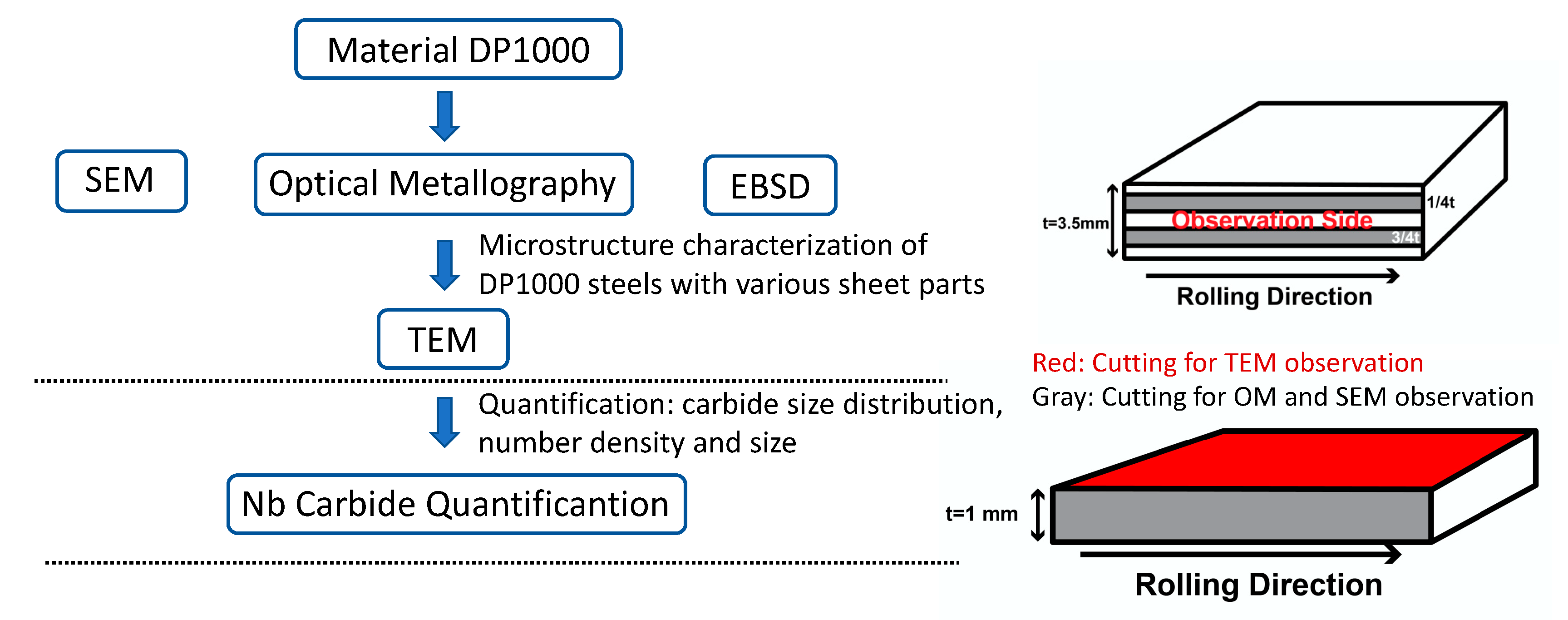
The sampling was done for three different process stages: in the as-hot rolled state, after batch annealing (580 °C/10 h) before cold rolling, and in the finished product. For detecting microstructural variations over the coil length and width, samples were taken at the head and tail of the coils, each in the strip center and at the strip edge. Sample preparation and the applied characterization techniques are shown in Figure 2.
Specimens for optical metallography (OM) and scanning electron microscopy (SEM) were mechanically polished and then etched with 3% Nital solution. Transmission electron microscopy specimens were prepared by cutting discs from the specimens. After being mechanically thinned to 0.06 mm, specimens were twin-jet electro-polished to perforation using a mixture of 5% perchloric acid, 15% glycerol, and 80% ethanol at a potential of 32 V and −2 °C. Transmission electron microscopy (TEM) observations were conducted using a Tecnai F30 field emission gun scanning transmission electron microscope (FEG-STEM) equipped with an energy dispersive spectrometer (EDS) and a Gatan 2001 energy filter (FEI Company, Hillsboro, OR, USA). The thickness of the TEM foil was calculated by electron energy loss spectroscopy (EELS). The microstructure of strip samples was observed in STEM mode and conventional TEM mode. The specimens for electron backscatter diffraction (EBSD) were prepared in the same way as the TEM specimens but with a shortened polishing time (i.e., without perforation). Observations were conducted with a FEI Tecnai Nova 450 field emission gun scanning microscope (FEG-SEM) equipped with an EDAX EBSD detector (FEI Company, Hillsboro, OR, USA). Step sizes of 150 nm were employed for the current experiments, and the EBSD acquisition areas were 50 × 50 µm2. The EBSD data were analyzed using the OIM Analysis 6.2 software (EDAX Inc., Mahwah, NJ, USA), which contains the built-in phase map functions necessary for the current research.
The phase percentages of ferrite, martensite and austenite were estimated by using OM and EBSD. To obtain reliable quantitative microstructural analysis, at least 10 EBSD maps were produced for each sample. The quality of the EBSD image was used to identify ferrite and martensite, and then to quantify the volume fraction of ferrite and martensite by the difference of their IQ (image quality) value. The austenite phase (FCC) was easily differentiated from ferrite and martensite (both BCC) and could be directly quantified by EBSD images. The grain size of each sample was determined by using OM images. The evaluation of NbC-carbide particle count and size was done by transmission electron microscopy. At least 5 TEM foils were analyzed for each condition. The carbide particles in the matrix were imaged using the STEM technique. The carbide number density was calculated for at least 2000 particles for each processing condition in strip positions.

3. Results

An initial screening of samples from different strip positions and processing stages is given in Figure 3. A large deviation of hardness in the as-hot rolled condition is observed at the tail-edge position. The value of around 300 HV is markedly higher than in the other positions (225–245 HV). This could be caused by a higher cooling rate at the tail-edge position. Spheroidizing annealing reduces the hardness to values slightly below the as-hot rolled stage and reduces the difference between the strip positions. Final annealing and rapid cooling into the dual phase microstructure increase the hardness to around 300 HV with little scattering over the various strip positions.

3.1. Characterization of As-Hot Rolled Condition

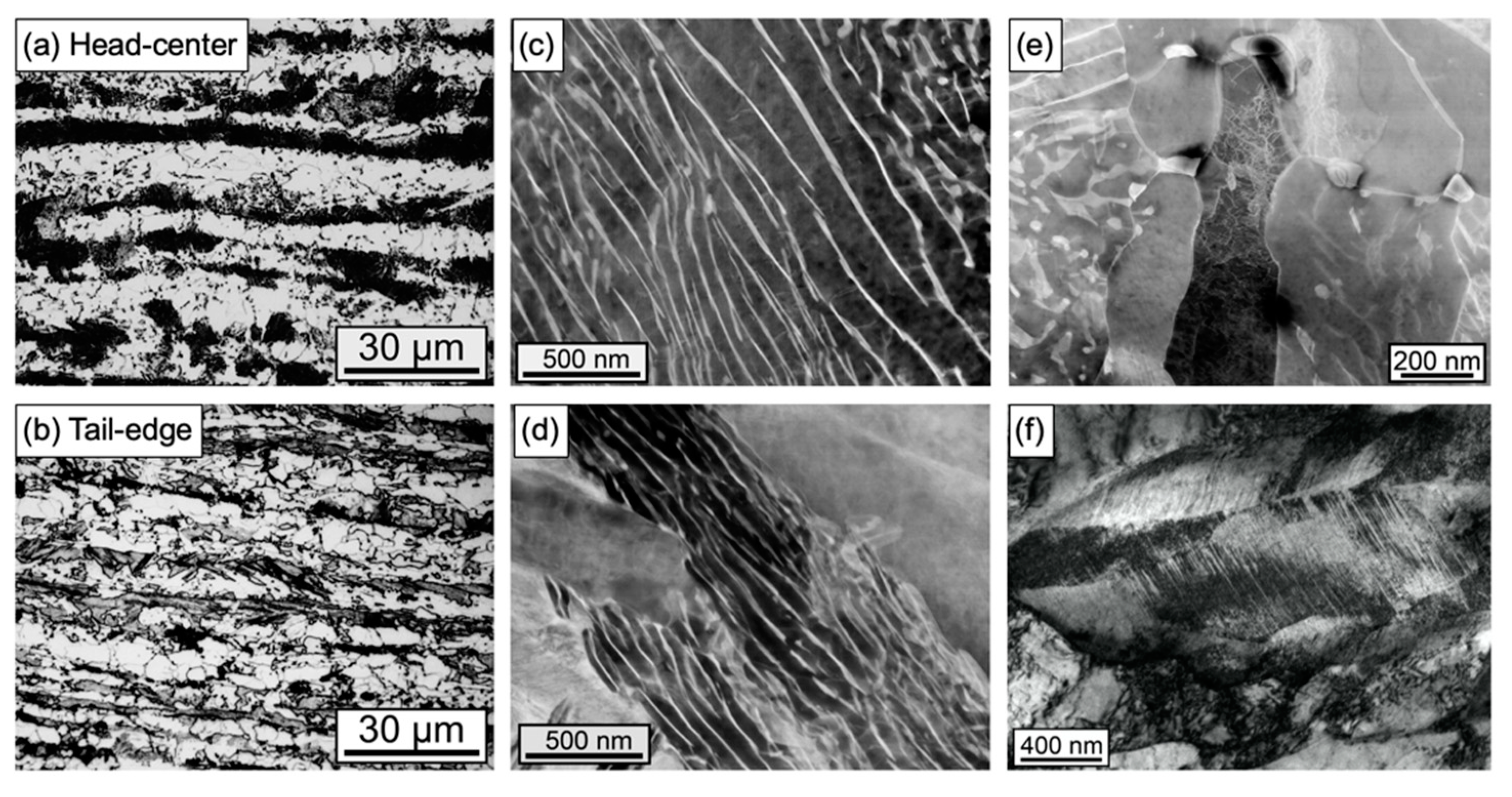
Light optical microscopy of the as-hot rolled material reveals at most of the strip positions a banded microstructure consisting of ferrite and pearlite (Figure 4a). The thickness of the ferrite and pearlite bands is in the range of 5–10 µm. The size of the ferrite grains is rather fine. Most of the ferrite grains are equiaxed having sizes in the range of 3–6 µm. Fewer grains have an elongated shape reaching sizes up to 15 µm along the rolling direction. The microstructure of material from the tail of the strip at the edge position is rather different (Figure 4b). Most of the bands that were pearlite at other strip positions appear to be martensite at the tail-edge position while only a few pearlite colonies are visible. At the head-center position of the strip pearlite lamella spacing is in the order of 200 nm (Figure 4c). Some areas show presence of degenerated pearlite as well as highly dislocated grains which are identified as lath martensite (Figure 4e). The pearlite found in the tail-edge position has finer lamella spacing (Figure 4d). Much of the carbon-rich phase is identified as twinned martensite adjacent to lath martensite (Figure 4f). These microstructural characteristics indicate that the coil cooling rate at the tail-edge position was higher than in the strip center and head positions. This also reflects in the measured hardness at the various strip positions (Figure 3).

3.2. Characterization of Batch Annealed Condition

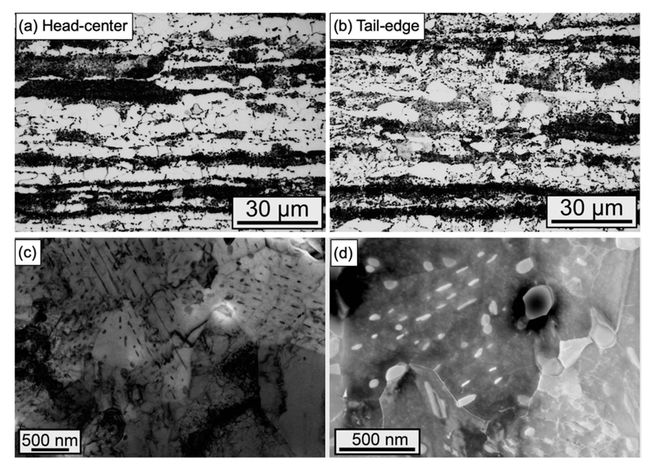
The microstructure in batch annealed condition necessarily comprises the same banded structure as the as-hot rolled strip (Figure 5a,b). However, the lamellar pearlite decomposes into spheroidal cementite (Figure 5c). The martensite region exhibits precipitates fine cementite particles in the tail-edge position (Figure 5d). However, some tempered martensite is maintained after annealing. This is reflected in a moderately higher hardness (230 HV) as compared to other strip positions (Figure 3) where the hardness is uniformly low at 210 HV.

3.3. Characterization of Final Condition

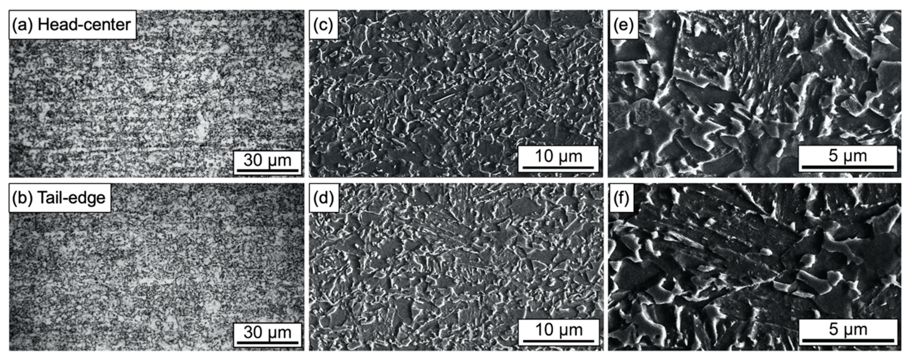
Final annealing and quenching in the galvanizing line produced an extremely fine-grained and homogeneous dual phase microstructure. Light optical microscopy shows the microstructure being nearly identical at all strip positions (Figure 6a,b). Occasionally, line-marking boundaries of ferrite grains along the rolling direction can be seen (Figure 6a), yet generally the distribution of phases is mostly balanced. While most of the ferrite grains have sizes in the range of 1–3 µm, few ferrite grains are around 5–7 µm in size. Scanning electron microscopy reveals that the hard phase is even finer appearing with a size of not more than 1 µm for the largest part, yet some martensite islands reach 3–4 µm of size (Figure 6c–f). The martensite islands are located along the boundary of ferrite grains as well as inside ferrite grains without forming banded agglomerations despite the rather large volume fraction of martensite phase.
Transmission electron microscopy identifies two types of martensite being formed, namely high- carbon twinned martensite and low-carbon lath martensite (Figure 7a). The lath martensite appears with a needle-like morphology, whereas the twin martensite has a blocky morphology in which lots of parallel streaking platelets can be identified. The appearance of twinned martensite is related to areas of high carbon as the present steel aims to produce retained austenite during processing. If carbon partitioning is not high enough to stabilize austenite down to room temperature, carbon-rich martensite will be formed. It is also possible that retained austenite has transformed into martensite during sample preparation. The interface between martensite and ferrite is decorated with a layer of geometrically necessary dislocations (Figure 7b).
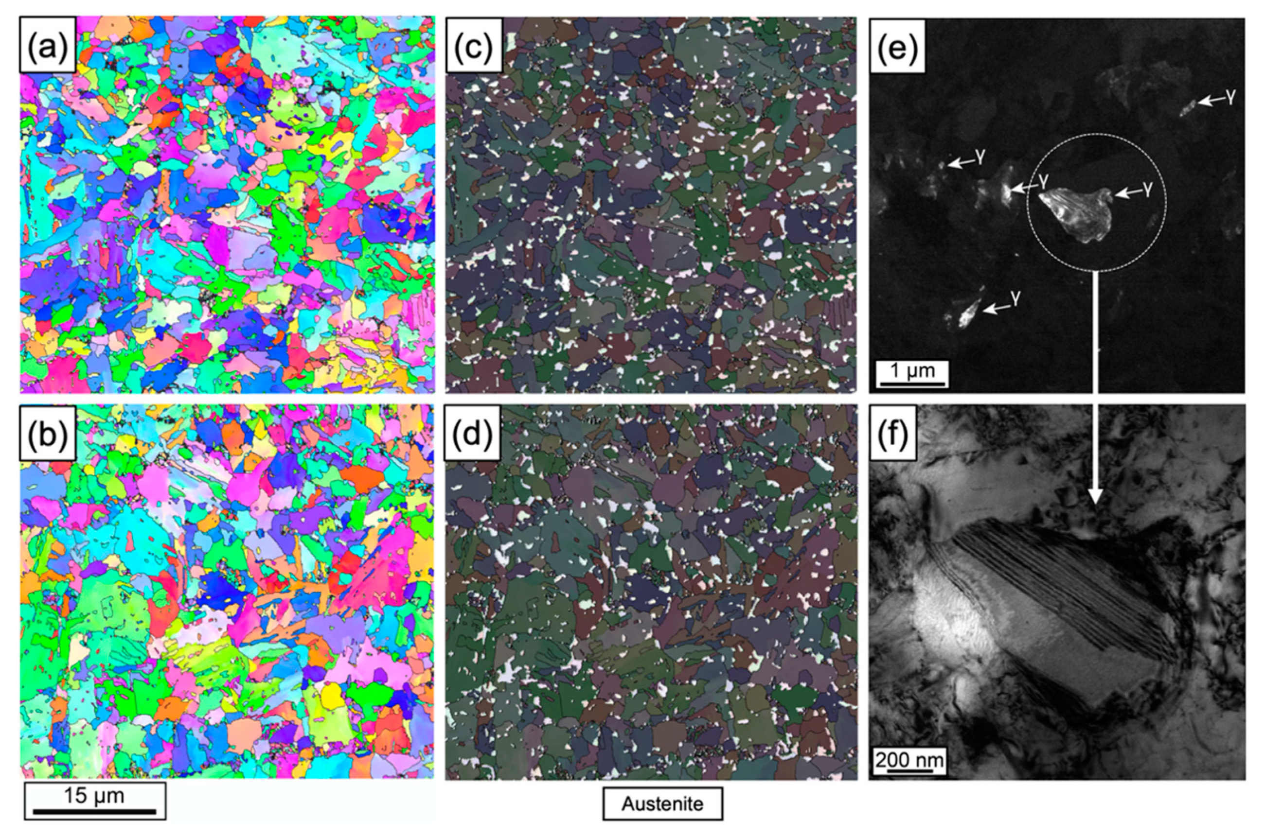
Electron backscattering diffraction (EBSD) analysis as shown in Figure 8a–d was used to identify the morphology and distribution of austenite phases in the microstructure. It appears that the austenite islands are well dispersed mostly at the grain boundaries and to a smaller part inside grains of the bcc phase. Figure 8e,f highlights details of individual austenite grains by high-resolution TEM. Their size is mostly below 1 µm. For all strip positions, the volume share of austenite phase was determined to range between 6% and 9%. It is feasible that the actual austenite share in the as-produced steel is somewhat higher since part of it is likely to transform into martensite during EBSD sample preparation. Table 2 summarizes the distribution of all phases at the different strip positions. The amounts of ferrite and martensite are nearly equal at around 45%. Only the tail-edge position comprises a little more martensite phase, which accounts for the marginally higher hardness observed in Figure 3.

3.4. Evolution of Niobium Precipitation

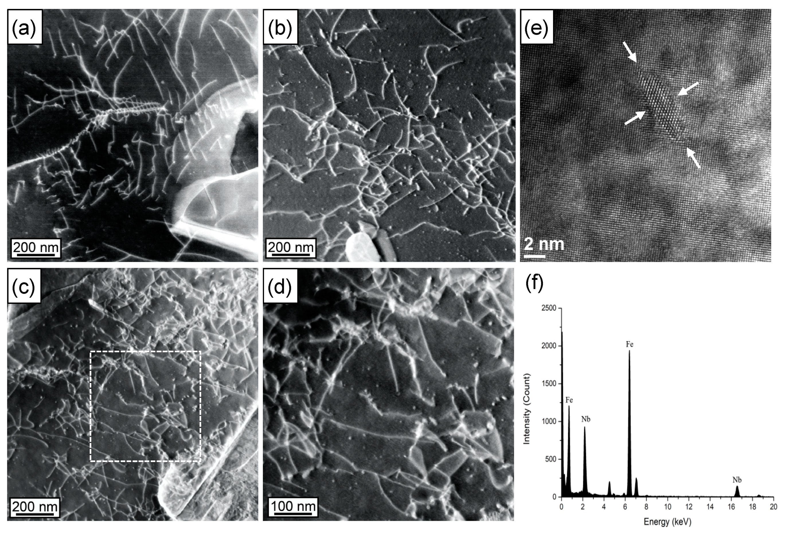
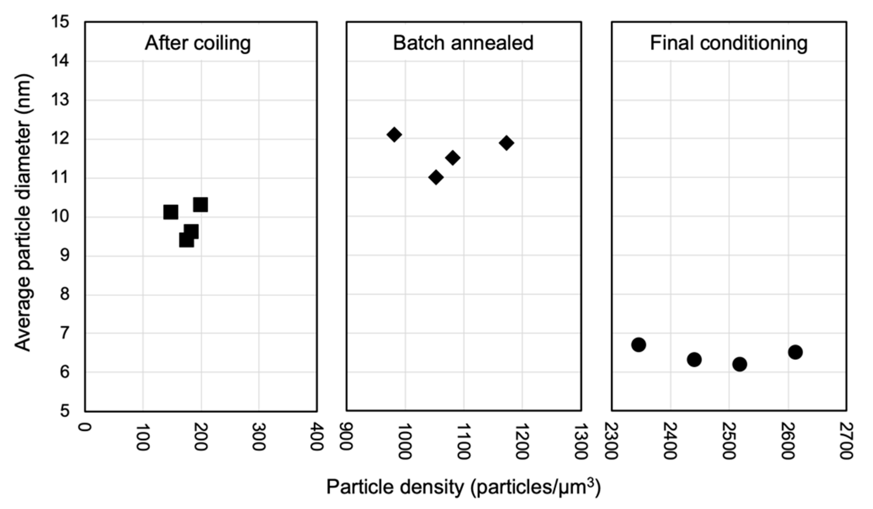
A main objective of the present work was tracing the precipitation status of Nb after the various treatment stages. The evaluation of particle count and size was done by transmission electron microscopy. Figure 9 exemplarily demonstrates the TEM precipitate analysis at the three processing stages. In the as hot-rolled stage, carbide particles were found in the ferrite phase (Figure 9a) and the particle amount is low. After batch annealing the particle density in the ferrite phase is significantly increased (Figure 9b). NbC precipitates were not found in the pearlite region neither in the as hot-rolled stage nor after batch annealing. In the final dual-phase microstructure particle density has further increased and also the dislocation density is larger (Figure 9c,d). Carbide particles were found in both martensite and ferrite grains. The high-resolution image of a NbC precipitate formed in the ferrite matrix after batch annealing (Figure 9e) indicates a high aspect ratio of the particle morphology. The EDX spectrum (Figure 9f) indicates a high level of Nb in the precipitates. Because the size of NbC is nanometer scaled, the electron beam spreads into matrix, causing the spectrum to show a high content of iron. Based on numerous samplings at the different strip positions the average particle size and particle density were evaluated as displayed in Figure 10. After any stage, the average particle size is not bigger than 12 nm. The low particle density having an average size of around 10 nm in the as-hot rolled condition is nearly identical at all strip positions despite the different cooling rate particularly at the tail-edge position. Long-term isothermal holding during batch annealing increases the particle density by roughly a factor of five. The average particle size appears to be slightly increased towards 12 nm. After the final short-term annealing process at higher temperature the particle density approximately doubles and the average size drops markedly to below 7 nm. The variation in the particle characteristics at various strip positions is very similar after either annealing treatment.
Table 3 summarizes the average particle size and density over the four strip positions. With these values, the particle volume fraction and the mass fraction of niobium bound by precipitation can be calculated. The density of NbC1-x depends on the Nb:C stoichiometry and varies between 7.73 and 7.80 g/cm3 [7]. For the present calculation the value of 7.80 g/cm3 was used. Regarding the particle volume, the particle shape was assumed to be spherical. However, this assumption leads to invalid results for the batch annealed condition as in this case particle morphology is typically lens- or disc-shaped. The particle count in batch-annealed condition is less than 50% of the final particle count, yet the particle size is largest. A volume estimation based on the particle morphology shown in Figure 9e suggests that around 70% of the available niobium is precipitated in this stage. After final annealing, practically all added niobium is indeed precipitated. The hot rolling and coiling conditions practiced in the production of this steel allow only about 10% of the niobium to precipitate.

4. Discussion

Niobium added to steel can contribute to both, microstructural refinement as well as precipitation strengthening. It is metallurgically active in solute as well as precipitate states. Depending on the processing conditions, a large discrepancy between equilibrium solubility and actual amount of solute niobium is possible, related to the kinetics of niobium precipitation. These effects will be discussed in the following.

4.1. Solubility Considerations and Precipitation Kinetics

Niobium added to steel typically precipitates as niobium carbonitride (Nb(C,N)) during or after solidification of the slab. For activating the metallurgical functionality of niobium, these Nb(C,N) precipitates need to be dissolved before hot rolling. The respective solubility product defined by Irvine et al. [8] as:
log [Nb][C + 12/14N] = 2.26 − 6770/T
where T is the absolute temperature, predicts a soluble niobium content [Nb] of almost exactly 300 mass ppm at a soaking temperature of 1240 °C considering the actual carbon and nitrogen content in the present DP steel. At a lower soaking temperature of for instance 1150 °C the soluble niobium content reduces to only 160 mass ppm. The significant amounts of manganese, silicon and chromium alloyed to the present DP steel have an influence on the carbon and nitrogen activities, thus also influence the niobium solubility. This can be accounted for by using respective interaction coefficients as defined by Sharma et al. [9]. It turns out that the solubility enhancing effect of Mn and Cr is quite well balanced out by the solubility reducing effect of Si. Accordingly, a soaking temperature of at least 1240 °C is required for the current steel chemistry to fully dissolve the contained amount of 0.03% Nb.
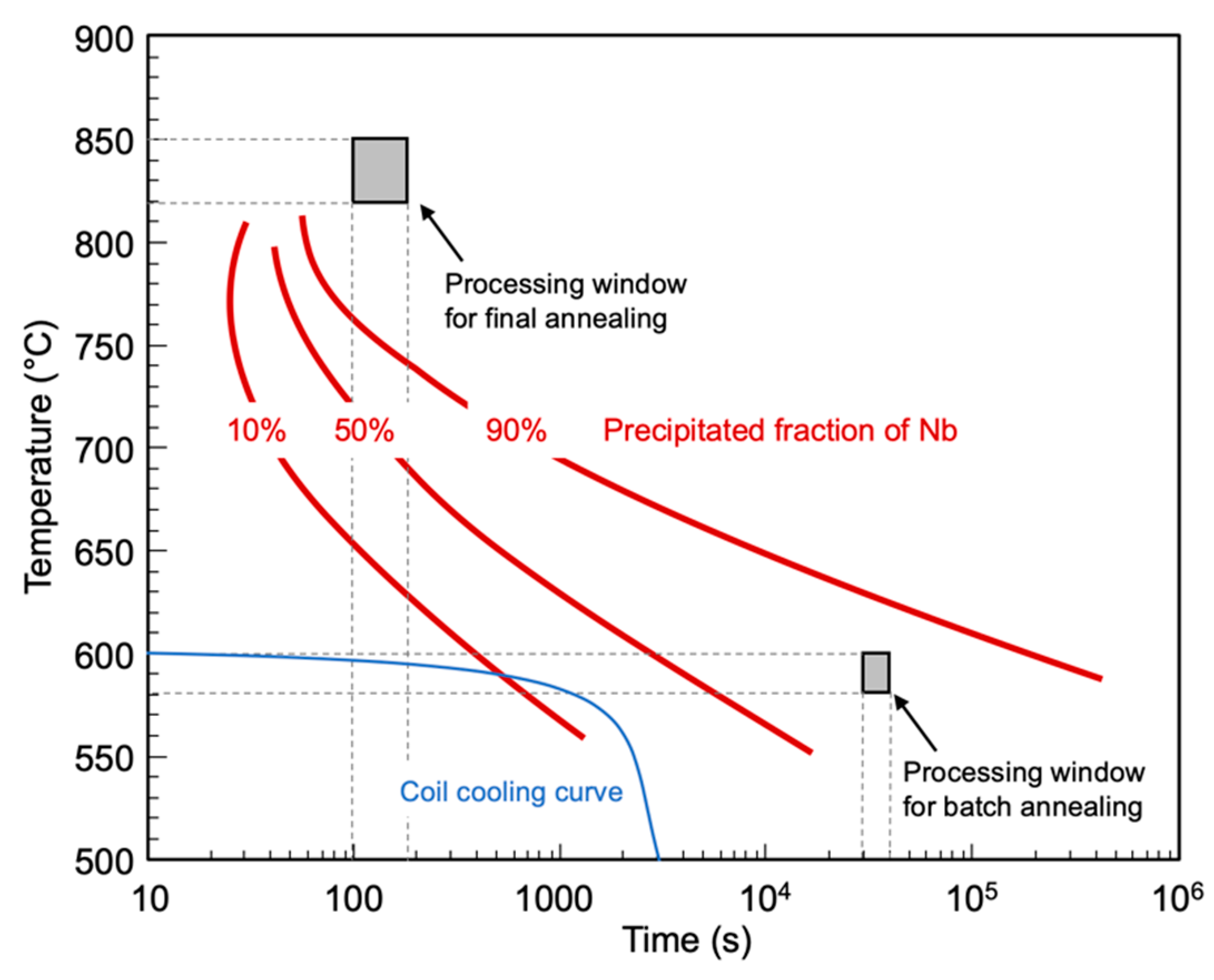
In the temperature range of finish hot rolling the solubility of niobium is drastically reduced to values below 30 mass ppm for temperatures below 950 °C. However, precipitation kinetics of NbC is rather sluggish due to the large mismatch in lattice constants of approximately 25% between the fcc niobium carbide and austenite impeding nucleation of the precipitate. Under the present rolling conditions in the hot strip mill with relatively high finishing temperature (above 900 °C), only a small fraction of strain induced NbC precipitates is expected. The quick cooling after finish rolling to a coiling temperature of around 600 °C barely provides a possibility for Nb precipitation on the run-out table of the hot strip mill. The solubility of niobium in ferrite is two orders of magnitude smaller than in the austenite phase at transformation temperature. Nucleation of precipitates is facilitated in ferrite as compared to austenite, since the precipitate can reduce lattice misfit by an orientation relationship with the host lattice. Danoix et al. [10] proposed a mechanism by which NbC particles form via metastable carbon-rich (Nb,Fe)C precursors. The slower diffusing Nb atoms replace iron atoms in those precursors with increasing ageing time achieving finally near-stoichiometric NbC [11]. Perrard et al. [12] performed detailed studies of the precipitation kinetics under comparable conditions, which are summarized in Figure 11. In a down-cooling coil diffusivity of Nb decreases with temperature reducing its diffusion range. Thus, the described precipitation mechanism will be interrupted. Coil cooling with a coiling temperature of 600 °C should allow precipitation in the order of 10 percent (Figure 11), which is in good agreement with the observations in the as-hot rolled steel (Table 3). Consequently, the hot rolled coil is highly super-saturated with solute Nb. According to the kinetics in Figure 11, the batch annealing treatment is expected to precipitate 60–70% of this solute Nb. Cold rolling heavily increases defect density in the steel so that niobium can efficiently diffuse and nucleate precipitates during the final annealing stage. The typical conditions of final annealing for DP steel in a continuous galvanizing line results in complete precipitation. These predictions are all in good agreement with the observations reported in Table 3.
Precipitates formed during batch annealing have an aspect ratio according to the observed particle morphology (Figure 9e). Niobium carbide precipitates (fcc) are known to adopt the Baker-Nutting orientation relationship in ferrite (bcc) [13] defined as (100)bcc // (100)fcc and [011]bcc // [010]fcc. The lattice misfit between the two phases is around 40% in the direction perpendicular to the (001) habit plane and around 10% in the direction parallel to the habit plane. Therefore, growth of the particle is facilitated along the low-misfit interface and obstructed in the normal direction. Ohnuma et al. [14] reported the presence of disc shaped NbC precipitates having a pronounced diameter-to-thickness aspect ratio after isothermal holding at 600 °C for several hours. The data of Perrard et al. [12] showed that the average aspect ratio of NbC precipitates formed during ageing treatment of ferrite is in the order of 2:1. With increasing precipitate diameter, they observed a large scatter in the aspect ratio reaching values up to 10:1. Particles observed in the present study have an aspect ratio of approximately 6:1 (Figure 9e).
At the onset of final annealing, the steel microstructure has a high defect density from the cold rolling process and part of the niobium is still available for precipitation. In the galvanizing line heating occurs with a fast rate reaching 850 °C, which is for the present alloy above the Ac3 temperature. Figure 11 indicates that, above 750 °C, precipitation kinetics becomes rather fast. One has to consider that in the intercritical temperature range ferrite and austenite coexist. In both phases the solubility of niobium is extremely low in that temperature range. However, the diffusivities of carbon and niobium as well as the driving force for NbC formation are considerably larger in ferrite than in austenite at the same temperature [15]. Furthermore, the defect density of newly formed austenite is low whereas ferrite depending on the progress of recrystallization has a higher defect density offering better nucleation conditions. For those reasons it can be expected that within the intercritical temperature range the remaining solute Nb preferentially precipitates in the ferrite phase. The partial lattice coherency of precipitates formed in the bcc lattice is lost upon transformation to austenite resulting in a completely incoherent interface with the matrix. The now incoherent disc-shaped precipitate can minimize its interfacial energy by spheroidization leading to a reduced particle diameter at constant volume. The large share of newly formed particles during the final annealing cycle of short duration typically have smaller diameters so that the average particle size decreases as appears from the data reported in Table 3.

4.2. Precipitation Strengthening

The population of ultrafine precipitates dispersed in the finished DP steel contributes to strength. Since the precipitates do not have a coherent interface with the matrix phase of the final DP steel, an Orowan-type mechanism is assumed to account for particle strengthening by which the passing dislocation bends around the particle leaving a dislocation loop behind. The strength increment by the conventional Orowan mechanism, σOrowan, [16] is described as:
σ Orowan = 0.8 · M · G · b L
where M is the Taylor factor, assumed having a value of 2.75 in the bcc lattice. The values of the shear modulus, G, and the Burgers vector, b, are 81.6 GPa and 0.248 nm, respectively. Assuming a random precipitate distribution, the average particle spacing, L, is related to the particle volume fraction f and average particle radius r as follows [17]:
  L = 2 π 3 f · r x
with x being the average cross-sectional diameter of the precipitate on the slip plane defined as:
  x = 2 2 3 · r
A modification of the conventional Orowan mechanism additionally takes into account the interaction between two dislocations with opposite signs in the vicinity of the particle. This so-called Ashby–Orowan mechanism [16] defines the strength increment as:
σ Ashby - Orowan = 0.8 · M · G · b 2 π · L 1 ν · ln ( x 2 b )
where the Poisson’s ratio, ν, for ferrite has a value of 0.29. The TEM measurements revealed an average particle diameter of 6.5 nm and an average particle count of 2480 µm−3 (Table 3) resulting in a particle volume fraction, f, of 0.034%, an average cross-sectional diameter, x, of 5.31 nm and an average particle spacing, L, of 248 nm. The calculated strength increment by precipitation assuming the conventional Orowan mechanism amounts to around 180 MPa (Equation (2)). Applying the modified Ashby–Orowan mechanism, the strength increase is calculated to be around 80 MPa (Equation (5)). During mass production of such DP steel it occasionally occurred that the effectively achieved slab soaking temperature was too low so that a considerable part of the contained niobium did not dissolve. DP steel produced from such “cold” slabs was observed to have their strength reduced by 60–80 MPa as compared to regular production average. This difference is well in the range predicted by the Ashby–Orowan mechanism (Equation (5)).

4.3. Microstructural Refinement and Homogenization

The transformation of the rather inhomogeneous initial microstructure of the as-hot rolled strip into a very homogeneous and fine-grained dual phase microstructure in the present steel is remarkable. Although a non-recrystallizing rolling schedule was not applied during hot rolling of this steel, the ferrite grain size is rather small. This is a consequence of the transformation retarding solutes such as manganese, chromium and niobium in the steel in combination with accelerated cooling from finish rolling to coiling temperature. The batch annealing results in spheroidization of the original pearlite and partial precipitation of niobium. Both features are highly relevant to the final annealing process. The cold rolling treatment is spreading the spheroidized cementite particles and introduces a high defect density acting as driving force for recrystallization.
During final annealing, several metallurgical processes occur sequentially or in competition with each other as described in detail by Huang et al. [18]. In conventional DP steel with low alloy content one can expect recrystallization to be nearly completed before austenite formation. A fast heating rate delays recrystallization and enhances the volume fraction of austenite at a given soaking temperature in the intercritcal region. Bunge et al. [19] remarked that the kinetics of ferrite recrystallization up to about 70 volume percent is governed by the kinetics of dissolution of fine iron carbide particles and the coarsening of larger ones. Thus, recrystallization proceeds ahead of austenite formation. Austenite nucleates preferably at the interface between recrystallized ferrite and spheroidized Fe3C [20]. When this process occurs at the ferrite grain boundary austenite grows in two directions, perpendicular to it (with a slower rate) and parallel to it (with a faster rate) resulting in a “necklace” of austenite grains around ferrite grains [18,21].
The DP steel discussed in the current study, however, is significantly different to conventional DP steel. First, the population of very stable niobium carbide particles produced by the prior batch annealing is nearly insoluble at the temperatures of final annealing, as discussed before. Particle coarsening is not occurring, and new particles of smaller size are being formed in situ (Figure 11). Therefore, ferrite recrystallization will be strongly obstructed. Secondly, the transformation proceeds at lower temperature due to the present high level of Mn. Upon the start of transformation, recrystallization is blocked, and the recrystallized ferrite fraction is diminished. These circumstances cause that austenitizing commences at an early stage of recrystallization, which is otherwise only possible at extremely high heating rate [18]. Many austenite nuclei can be formed not only at the grain boundary but also in the interior of grains due to high defect density in unrecrystallized ferrite. The many simultaneously growing austenite grains obstruct each other resulting in a limited size. Additionally, the stable NbC particle population exerts strong austenite grain boundary pinning limiting austenite grain growth.
At the practiced annealing temperature of 850 °C, the investigated steel should be fully austenitic. Schemmann et al. [22] however reported that a 0.2%C-1.5%Mn-0.25%Si DP steel showed incomplete austenitization although it was also nominally annealed above Ac3 temperature (840 °C). They explained the observation by ferrite being kinetically stabilized in Mn depleted regions existing in the steel. For coiling temperatures resulting in pearlitic-ferritic hot strip microstructure, as was the case in the present study, Mn is partitioning to carbides (cementite) after coiling. The steel of the present study containing a high Mn level (>2.2%) provides conditions for Mn partitioning to cementite not only during coiling but also during the batch annealing treatment. Schemmann et al. [22] further argued that Mn does not completely homogenize after cementite dissolution in the final annealing treatment. The Mn enriched regions promote austenite stabilization during rapid cooling. Consequently, the retained austenite distribution should be related to that of former cementite particles. Figure 5a,b reveals that, after batch annealing, cementite particles are present not only in the area of pearlite colonies, but also within ferrite bands due to the cold reduction treatment applied to this microstructure. The retained austenite distribution in Figure 8c,d comprises aligned clusters of larger austenite islands likely representing areas of former pearlite colonies as well as smaller scattered austenite islands originating from individual cementite particles located within the former ferrite bands. Following the argumentation of [22] it is reasonable to assume that the vicinity of these austenite islands is Mn-depleted and Si-enriched, which preserve kinetically stabilized ferrite during final annealing without depending on nucleation of new ferrite upon slow cooling. This is concluded being the reason for the observed homogeneous distribution of ferrite and martensite islands the final DP microstructure.

4.4. Microstructural Implications on Mechanical Properties

The steel described in this investigation is industrially produced material belonging to the family of “cold rolled dual phase steels with improved formability” according to industry standard VDA239-100. The specified mechanical properties of such grades are listed in Table 4. The typically achieved values of this product also reported in Table 4 indicates that this steel excellently fulfils the requirements for grade CR700Y-980T-DH. The total elongation (A80) is markedly better than specified. Figure 12a shows representative stress-strain curves obtained from the present steel. The values for yield strength (Rp0.2), tensile strength, homogeneous elongation and total elongation are 721 MPa, 1051 MPa, 12.5% and 16.7%, respectively. The work hardening behavior, derived from the stress-strain data is demonstrated in Figure 12b. The strain hardening exponent (n-value) is extraordinarily high at the very beginning of deformation followed by a rapid decrease to values between 0.12 and 0.14. The work hardening rate increases again at higher strain when the transformation induced plasticity (TRIP) effect is activated reaching a maximum value of around 0.18 after which a continuous decrease proceeds until the Considère criterion is met at a true strain of approximately 0.125.
The mechanical properties of the present DP steel are related to the described microstructural characteristics in the following ways:
  • Grain refinement is known to raise strength and toughness simultaneously. In conventional high strength steels with ferritic, ferritic-pearlitic or bainitic matrix grain refinement has a stronger effect on yield than on tensile strength. Thus, the cold working potential is diminished, and uniform elongation is reduced. In DP steel the influence of grain refinement however is opposite [24,25]. Consequently, the work hardening potential will be enhanced by refining the microstructure. The Hall–Petch coefficients for yield and tensile strength in DP steels related to ferrite grain size were determined by Ramazani et al. [26] as being 3.98 and 8.39 MPa∙mm−1/2, respectively. Accordingly, the strengthening contribution resulting from ferrite grain size in the present steel is estimated to be in the order of 70 and 150 MPa for yield and tensile strength, respectively. In comparison to typically coarser grained conventional DP steel with similar martensite volume fraction, the tensile strength increment by grain refinement is expected to reach up to 100 MPa [24,25].
  • Precipitation strengthening in the ferrite phase [27] in combination with grain refinement results in more homogeneous strain distribution within the microstructure with the potential of postponing plastic instability or necking of the material towards higher strains, i.e., an improved strength-ductility balance can be expected.
  • The very fine martensite size and the good separation of martensite islands from each other in the present steel is expected reducing void nucleation and growth along ferrite/martensite interfaces as well as obstructing cleavage fracture in martensite islands.
  • The nano-sized niobium carbides dispersed within ferrite phase are expected to significantly increase dislocation density in the very beginning of deformation leading to large instant work-hardening. The dislocation loops formed around the precipitates reduce the effective mean-free path length (parameter L in Equation (5)) between particles with increasing Ashby-Orowan strengthening, i.e., work hardening as a consequence. With the progress of deformation, cross-slip on secondary slip planes can be activated in the vicinity of particles resulting in dynamic recovery [28]. Differential strain hardening analysis by Suppan et al. [6] on a similar high-ductility DP steel indeed observed such recovery behavior after initial straining. The work hardening behavior observed in the present steel (Figure 12b) reveals the same phenomenon after the initial very high strain hardening rate.
  • The sequence of instant strain hardening by precipitates, followed by increasing dislocation pile-up against grain or phase boundaries, and finally retained austenite transformation provides a continuously high strain hardening rate over a wide deformation range. In this steel the strain hardening coefficient varies between 0.12 and 0.18 until homogeneous elongation is reached. It guarantees high strength in a formed component irrespective of the actual degree of strain in local areas of the part.

5. Conclusions

This investigation has shown that niobium microalloying to dual phase steels significantly contributes to strength by precipitation of ultrafine particles as well as by microstructural refinement. In addition, properties relevant to formability are being improved.
It can be concluded that the pronounced refinement of the DP microstructure is related to a strong recrystallization delay of the cold rolled ferrite matrix by niobium carbide precipitates in the final annealing cycle leading to austenite formation before recrystallization is completed. The precipitates further restrict grain growth during the soaking phase of the final annealing cycle.
The batch annealing treatment practiced before cold rolling has a remarkable metallurgical significance in addition to original intention of softening the as-hot rolled steel. This intermediate annealing treatment produces a very fine-sized niobium carbide precipitate population and results in pearlite spheroidization. Both features are relevant to microstructural refinement and homogeneous phase distribution in the final DP steel.
Niobium must be completely dissolved during slab reheating for fully activating its metallurgical functionality. The current steel chemistry with addition of 0.03%Nb requires a soaking temperature of at least 1240 °C. With the typical hot rolling schedules applied for theses steel grades, a large share of niobium remains solute in the as-hot rolled strip.
With 0.03% niobium being metallurgically active and applying the described sequence of batch and continuous annealing processes, a combined tensile strength contribution of up to 180 MPa as compared to Nb-free steel can be expected. The effects related to niobium microalloying are very similar at all investigated strip positions and are thus rather insensitive to temperature variations occurring along and across the hot rolled strip during coiling.

Author Contributions

Conceptualization, H.M. and T.H.; methodology, J.-R.Y.; investigation, Y.-W.C.; writing—original draft preparation, H.M.; writing—review and editing, H.M.; J.-R.Y.; J.R.; T.H. All authors have read and agreed to the published version of the manuscript.

Funding

This research received no external funding.

Conflicts of Interest

The authors declare no conflict of interest.

References

  1. Hasegawa, K.; Kawamura, K.; Urabe, T.; Hosoya, Y. Effects of Microstructure on Stretch-flange-formability of 980 MPa Grade Cold-rolled Ultra High Strength Steel Sheets. ISIJ Int. 2004, 44, 603–609. [Google Scholar] [CrossRef]
  2. Pichler, A.; Traint, S.; Hebesberger, T.; Stiaszny, P.; Werner, E. Processing of thin sheet multiphase steel grades. Steel Res. Int. 2007, 78, 216–223. [Google Scholar] [CrossRef]
  3. Mohrbacher, H.; Klinkenberg, C. The Role of Niobium in Lightweight Vehicle Construction. Mater. Sci. Forum 2007, 537–538, 679–685. [Google Scholar] [CrossRef]
  4. Flaxa, V.; Kluge, S. Microalloyed Low-Carbon Multiphase Steels. Steel Res. Int. 2016, 87, 1264–1273. [Google Scholar] [CrossRef]
  5. Bouaziz, O.; Zurob, H.; Huang, M. Driving Force and Logic of Development of Advanced High Strength Steels for Automotive Applications. Steel Res. Int. 2013, 84, 937–947. [Google Scholar] [CrossRef]
  6. Suppan, C.; Hebesberger, T.; Pichler, A.; Rehrl, J.; Kolednik, O. On the microstructure control of the bendability of advanced high strength steels. Mater. Sci. Eng. A 2018, 735, 89–98. [Google Scholar] [CrossRef]
  7. Ordan’yan, S.S.; Avgustinik, A.I.; Kudryasheva, L.V. Densification of nonstoichiometric Niobium-carbide phases. Powder Metall. Met. Ceram. 1968, 7, 612–618. [Google Scholar]
  8. Irvine, K.J.; Pickering, F.B.; Gladman, T. Grain-refined C-Mn steels. J. Iron Steel Inst. 1967, 205, 161–182. [Google Scholar]
  9. Sharma, R.C.; Lakshmanan, V.K.; Kirkaldy, J.S. Solubility of Niobium Carbide and Niobium Carbonitride in Alloyed Austenite and Ferrite. Metall. Trans. A 1984, 15, 545–553. [Google Scholar] [CrossRef]
  10. Danoix, F.; Bémont, E.; Maugis, P.; Blavette, D. Atom Probe Tomography I. Early Stages of Precipitation of NbC and NbN in Ferritic Steels. Adv. Eng. Mater. 2006, 8, 1202–1205. [Google Scholar] [CrossRef]
  11. Hin, C.; Bréchet, Y.; Maugis, P.; Soisson, F. Kinetics of heterogeneous dislocation precipitation of NbC in alpha-iron. Acta Mater. 2008, 56, 5535–5543. [Google Scholar] [CrossRef]
  12. Perrard, F.; Deschamps, A.; Bley, F.; Donnadieu, P.; Maugis, P. A small-angle neutron scattering study of fine-scale NbC precipitation kinetics in the a-Fe–Nb–C system. J. Appl. Cryst. 2006, 39, 473–482. [Google Scholar] [CrossRef] [Green Version]
  13. Baker, R.G. Nutting, J. Precipitation Processes in Steels. J. Iron Steel Inst. Spec. Rep. 1959, 64, 1–22. [Google Scholar]
  14. Ohnuma, M.; Suzuki, J.; Wie, F.-G.; Tsuzaki, K. Direct observation of hydrogen trapped by NbC in steel using small-angle neutron scattering. Scr. Mater. 2008, 58, 142–145. [Google Scholar] [CrossRef]
  15. Nöhrer, M.; Mayer, W.; Primig, S.; Zamberger, S.; Kozeschnik, E.; Leitner, H. Influence of Deformation on the Precipitation Behavior of Nb(CN) in Austenite and Ferrite. Metall. Mater. Trans. A 2014, 45A, 4210–4219. [Google Scholar] [CrossRef]
  16. Ashby, M.F. Physics of Strength and Plasticity; Argon, A.S., Ed.; MIT Press: Cambridge, MA, USA, 1969; p. 113. [Google Scholar]
  17. Guo, Z.; Sha, W. Quantification of Precipitation Hardening and Evolution of Precipitates. Mater. Trans. 2002, 43, 1273–1282. [Google Scholar] [CrossRef] [Green Version]
  18. Huang, J.; Poole, W.J.; Militzer, M. Austenite Formation during Intercritical Annealing. Metall. Mater. Trans. A 2004, 35A, 3363–3375. [Google Scholar] [CrossRef]
  19. Bunge, H.J.; Vlad, C.M.; Kopp, H.-H. Recrystallization kinetics of a cold rolled dual-phase steel sheet. Arch. Eisenhüttenwesen 1984, 55, 163–168. [Google Scholar] [CrossRef]
  20. Garcia, C.I.; DeArdo, A.J. Formation of Austenite in 1.5 Pct Mn Steels. Metall. Trans. A 1981, 12A, 521–530. [Google Scholar] [CrossRef]
  21. Nakada, N.; Arakawa, Y.; Park, K.-S.; Tsuchiyama, T.; Takaki, S. Microstructural Control of Dual Phase Structure formed by Partial Reversion from cold-deformed Martensite. Mater. Sci. Forum 2013, 753, 191–194. [Google Scholar] [CrossRef]
  22. Schemmann, L.; Zaefferer, S.; Raabe, D.; Friedel, F.; Mattissen, D. Alloying effects on microstructure formation of dual phase steels. Acta Mater. 2015, 95, 386–398. [Google Scholar] [CrossRef]
  23. Available online: www.vda.de/en/services/Publications/vda-239-100.html (accessed on 1 February 2020).
  24. Park, K.-T.; Lee, Y.K.; Shin, D.H. Fabrication of Ultrafine Grained Ferrite/Martensite Dual Phase Steel by Severe Plastic Deformation. ISIJ Int. 2005, 45, 750–755. [Google Scholar] [CrossRef] [Green Version]
  25. Calcagnotto, M.; Ponge, D.; Raabe, D. Effect of grain refinement to 1 µm on strength and toughness of dual-phase steels. Mater. Sci. Eng. A 2010, 527, 7832–7840. [Google Scholar] [CrossRef]
  26. Ramazan, A.; Mukherjee, K.; Prahl, U.; Bleck, W. Transformation-Induced, Geometrically Necessary, Dislocation-Based Flow Curve Modeling of Dual-Phase Steels: Effect of Grain Size. Metall. Trans. A 2012, 43A, 3850–3869. [Google Scholar] [CrossRef]
  27. Kamikawa, N.; Hirohashi, M.; Sato, Y.; Chandiran, E.; Miyamoto, G.; Furuhara, T. Tensile Behavior of Ferrite-martensite Dual Phase Steels with Nano-precipitation of Vanadium Carbides. ISIJ Int. 2015, 55, 1781–1790. [Google Scholar] [CrossRef] [Green Version]
  28. Kamikawa, N.; Abe, Y.; Miyamoto, G.; Funakawa, Y.; Furuhara, T. Tensile Behavior of Ti, Mo-added Low Carbon Steels with Interphase Precipitation. ISIJ Int. 2014, 54, 212–221. [Google Scholar] [CrossRef] [Green Version]
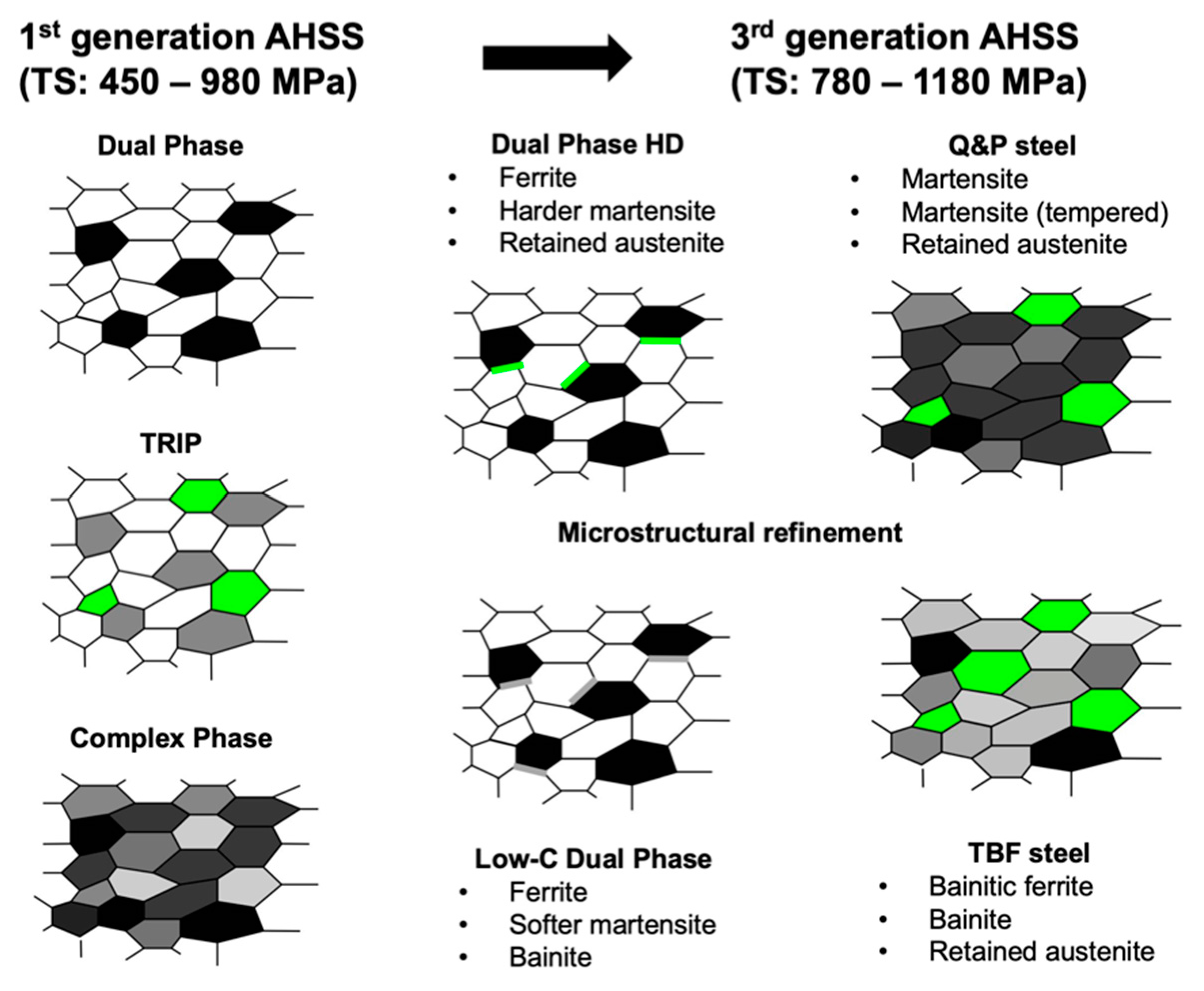
Figure 1. Microstructural evolution of advanced high strength steels for automotive applications (white: ferrite, black: martensite, green: retained austenite, grey: bainite and tempered martensite).
Metals 10 00504 g001
Figure 2. Methods and sample preparation for microstructural characterization.
Metals 10 00504 g002
Figure 3. Hardness measurements (HV1) at various coil positions and treatment stages in the hot rolling mill (HRM), cold rolling mill (CRM) and continuous galvanizing line (CGL); hardness-relevant metallurgical influences of intermediate processes are indicated by arrows.
Metals 10 00504 g003
Figure 4. Microstructure in as hot rolled condition: (a,b) light optical microscopy; (c,d) TEM (Transmission electron microscope) details of lamellar pearlite; (e,f) TEM details of martensitic phases.
Metals 10 00504 g004
Figure 5. Microstructure of as-hot rolled steel in batch annealed condition: (a,b) light optical microscopy; (c,d) transmission electron microscopy.
Metals 10 00504 g005
Figure 6. Microstructure of cold rolled steel after final conditioning: (a,b) light optical microscopy; (c,d) scanning electron microscopy; (e,f) SEM (scanning electron microscopy) higher magnification.
Metals 10 00504 g006
Figure 7. Identification of microstructural details after final conditioning by TEM: (a) co-existence of lath (L) and twinned (T) martensite; (b) geometrically necessary dislocations (GND) at boundary between ferrite and martensite; (c,e) twinned martensite; (d,f) lath martensite.
Metals 10 00504 g007
Figure 8. EBSD characterization of final DP microstructure: (a,c) head-center, (b,d) tail-edge and identification of the retained austenite phase (white colored grains on the EBSD background (c,d)); TEM characterization of austenite grains: (e) dark field image, (f) bright field image of detail in (e).
Metals 10 00504 g008
Figure 9. Evolution of niobium precipitation during processing stages characterized by TEM: (a) as hot rolled; (b) after batch annealing; (c) after hot dip galvanizing; (d) higher magnification of dashed area marked in (c); (e) representative high-resolution image of NbC precipitate in ferrite matrix after batch annealing; (f) EDX spectrum indicating a high level of Nb in the precipitates.
Metals 10 00504 g009
Figure 10. Size and particle density analysis of niobium precipitates for the different processing conditions at four strip positions.
Metals 10 00504 g010
Figure 11. Precipitation kinetics of niobium in the ferrite phase; various time-temperature scenarios applied during processing of DP steel in the current study are indicated.
Metals 10 00504 g011
Figure 12. (a) Stress-strain curve obtained from uniaxial tensile test; (b) evolution of strain hardening exponent in function of true strain (dashed line represents the Considère criterion).
Metals 10 00504 g012
Table 1. Chemical composition and main processing temperatures of DP980 HD (high ductility) steel.
Alloy (Mass%)CMnSiCrNbTiB
DP980 HD:≈0.22.2–2.60.5–1.0<0.70.03<0.02<0.003
Processing StageSlab SoakingFinish RollingCoilingBatch AnnealingContinuous Annealing
Temperature:1240 °C>900 °C≈600 °C580 °C/10 h850 °C
Table 2. Quantitative evaluation of phases at various positions in the col after hot-dip galvanizing.
Position in StripPhase Share (%)
FerriteMartensiteAustenite
Head-center44488
Head-edge46468
Tail-center45487
Tail-edge42526
Table 3. Quantitative evaluation of Nb precipitates at various processing stages (average values).
Processing StageParticle Size (nm)Particle Count (µm−3)Particle Volume Fraction (%)Amount (ppm)/Share (%) of Precipitated Nb
Hot rolled9.61880.00435/10%
Batch annealed11.610720.023~200/~70%1
Final conditioning6.524800.034303/100%
1 estimated value based on observed particle diameter-to-thickness ratio (Figure 9e).
Table 4. Specified mechanical properties (measured in longitudinal direction) of cold-rolled dual phase steels with improved formability acc. to standard VDA 239-100 [23].
Steel GradeYield Strength Rp0.2 (MPa)Tensile Strength Rm (MPa)Elongation at Fracture A80 (%)n-value
n4-6n10-20 / Ag
CR440Y780T-DH440–550780–900≥18≥0.18≥0.13
CR700Y980T-DH700–850980–1180≥13--
Current production (typical values)740103015≥0.14≥0.12