Article

Effect of Hybrid Ultrasonic and Mechanical Stirring on the Distribution of m-SiCp in A356 Alloy

1
CMEMS-Uminho, Department of Mechanical Engineering, University of Minho, 4800-058 Guimarães, Portugal
2
MEtRICs-UMinho, Department of Mechanical Engineering, University of Minho, 4800-058 Guimarães, Portugal
*
Author to whom correspondence should be addressed.
Metals 2020, 10(5), 610; https://doi.org/10.3390/met10050610
Submission received: 28 March 2020 / Revised: 17 April 2020 / Accepted: 6 May 2020 / Published: 8 May 2020
(This article belongs to the Special Issue The Use of Ultrasonic Technology in the Treatment of Light Alloys)

Abstract

:
The present study details the micro-scale silicon carbide particle (m-SiCp) homogeneous distribution in an A356 alloy through hybrid ultrasonic-stirring melt treatment under different operation conditions. Ultrasonically excited fluids were studied by particle image velocimetry to estimate the efficiency of the acoustic streaming in different distances to the sonotrode. Distinct particle approaches to introduce the melt and stirring techniques were performed to determine a successful route to promote a homogenous distribution of reinforcement particles. Results showed that the addition of m-SiCp in the semisolid state significantly improved particle wettability, preventing rapid sedimentation. The combination of ultrasonic induced streaming and mechanical stirring is an effective tool for the homogeneous distribution of m-SiCp along the casting specimen.

1. Introduction

In recent years, increasingly restrictive regulations regarding air pollution [1] have been imposing reductions on fuel consumption and emissions, thus leading to the demand for lightweight vehicle production [2]. As a result, the increasing trend in light alloy usage, namely Al and Mg-based, for the production of structural components underwent major developments [3]. Moreover, conventional alloys have reached their limits concerning their mechanical properties. Thus, finding effective and reliable solutions to develop new alloys as well as new technologies for their processing remains a demanding challenge.
Currently, different production techniques for metal matrix composites (MMCs) may be classified according to the matrix state such as (i) liquid; (ii) semi-solid processes; or (iii) solid [4]. Frequently, these methods use solid/semi-solid powder metallurgy approaches such as hot isostatic pressure [5] or plasma spark sintering [6]. Compared to these methods, the liquid route for Al-MMC processing presents the most promising evidence in terms of potential to be scalable to industrial levels, allowing competitiveness even with high processing volume. They may be explored through different techniques such as mechanical stirring [7,8,9,10], which may have gas injection [11,12], and ultrasonic vibration [13,14,15]. Regarding mechanical stirring, despite its attractive low cost and potential to be scalable [16], it has reported drawbacks such as non-homogeneous particle dispersion [17,18] and weak interface bonding between particles and the metal matrix [19,20]. This makes it an inefficient way to manufacture high performance micro-reinforced components, which commonly leads to the partial incorporation of the particles in the molten metal. On the other hand, ultrasonic vibration, which involves dipping and operation of an acoustic radiator in the melt, has been referred to as a more effective solution [21], thus promoting a more uniform distribution of reinforcements across the base matrix. The combination of ultrasonic vibration and stirring is expected to be a highly efficient route for particle dispersion/distribution, and a solution to overcome the referred drawbacks. During cavitation, the shock waves released by the implosion of bubbles break apart the particle clusters. Additionally, the developed acoustic streaming flow promotes the dispersion of particles throughout the liquid metal.
The present work studied the different approaches for particle integration and dispersion in A356 melts. Particle image velocimetry (PIV) was used to assess the ability of ultrasonic tools to disperse m-SiCp. This technique was combined with mechanical stirring to further enhance the particle movement and prevent sedimentation. Additionally, m-SiCp was added in semi-solid and liquid states to analyze the particle bonding within the A356 matrix.

2. Methodology

2.1. Particle Image Velocimetry Setup

2D particle image velocimetry (PIV) was used to analyze the distributional flow field imposed by the ultrasonic (US) excitation using a Ti6Al4V sonotrode while immersed in water with tracer particles. The experimental setup (Figure 1) consisted of a double pulse laser, which generates a laser sheet illuminating a 2D plan across the ultrasonicated flow in two short pulses, and a charge-coupled device camera (CCD-Hisense Zyla, Dantec Dynamics, Skovlunde, Denmark) that recorded the images of the flow field. m-SiCp powder, later used as a reinforcement particle, was used as a tracer particle, being homogeneously scattered in the medium and monitored by the overall laser/CCD system.
A CCD camera was placed facing the ultrasonic system, while the double pulse laser (Dantec Dynamics-145 mJ energy and 532 mm wavelength, Skovlunde, Denmark) was emitted in a perpendicular direction. The laser irradiates a light plane in the medium with a time interval (∆t) between pulses, thus allowing the sequential contrast of moving particles for the mean flow velocity magnitude and direction calculation. The CCD camera was equipped with a 50 mm Zeiss (Dantec Dynamics, Skovlunde, Denmark) with f-power set at 1.4. This implies that the overall pixel size was 6.5 μm with a pixel resolution of 2560 × 2160 (5.5 Megapixel). Dynamic Studio software was applied for data acquisition and image processing. The short time interval between images allowed for the capture of the seeding particle displacement from one image to another. The acquired images were divided into interrogation areas, from which velocity vectors were extracted by performing mathematical correlation analysis in each area between the two frames. In the end, the instantaneous velocity field of the flow was obtained so that the analysis of the velocity field in time could be conducted.

2.2. Ultrasonic Melt Stirring for Microparticles Dispersion

The experimental apparatus (Figure 2a) used to perform the dispersion of m-SiCp consisted of ultrasonic-stirring equipment that used a MMM (Multi-frequency, Multimode, Modulated technology) ultrasonic power supply unit developed by MPInterconsulting. The present system was composed of a 3 kW power piezoelectric transducer, a Ti6Al4V waveguide (Ø = 35 mm and L = 95 mm), and a Ti6Al4V acoustic radiator (Ø = 20 mm and L = 245 mm). The overall equipment was prepared to be lowered and positioned into a resistance furnace holding a 1 L SiC crucible. This technique and configuration are designed to not only disperse the m-SiCp, but also to simultaneously promote melt treatment through physical processing (e.g., degassing, grain refinement, and secondary phase modification) [22,23,24,25]. For tests resorting only to mechanical stirring, the following protocol was adopted (Figure 2b): (i) Axial (50 mm, full range up–down) movement with a 10 s period (5 mm/s) and (ii) translational motion with a 25 mm radius with a 20 rpm counterclockwise movement (~52 mm/s). This movement assures that the overall upper medium of the crucible is contemplated by a screw type movement due to the higher linear velocity in rotation, relative to the axial linear velocity. It is known that the rate of stirring has a significant effect on the inclusion of hydrogen and oxide bifilms [26], however, the use of a translation movement is able to avoid these issues. The absence of an impeller, thus high speed rotation in turbulent paddle rotation, is able to prevent known issues such as local vortices, sloshing, and axial flow from the impeller [26,27,28].
The m-SiCp particles used in this study were characterized considering their size distribution (Figure 3). It was observed that they had a typical angular/irregular shape and their mean size was 5.1 (±2.9) μm. It is highlighted that their size distribution was not normally distributed by the existence of a large probability of finding m-SiCp with sizes in the range of 1–2 μm.
The A356 alloy (composition in Table 1) was sectioned into 0.2 kg loads, being posteriorly degreased, dried, and placed in the pre-heated crucible (400 °C). To study the influence of pre-heated m-SiCp adding approaches and distribution in the alloy, 1% (in mass) of particles were introduced in the melt using different conditions (Table 2): (i) Condition 1: m-SiCp added after alloy melting considering a 30 min homogenization isothermal period at 700 °C, after which US vibration was imposed in the melt for 1 min; (ii) Condition 2: m-SiCp added in semisolid state and US vibration was performed for 1 min isothermally at 700 °C; and (iii) Condition 3: m-SiCp added in a semisolid state and US vibration and mechanical stirring were performed for 2 min isothermally at 700 °C. Subsequently to the US treatment, melts of all test conditions were poured into a pre-heated (300 °C) steel die.
When the particles are introduced in the semi-solid state (Conditions 2 and 3), an additional step has to be included in the melt processing. After the isothermal homogenization period, the melt was allowed to cool down to 595 °C, allowing the melt to be in a semi-solid state. This state was maintained for a 15 min period to allow a system temperature stabilization. Only then was the pre-heated m-SiCp added to the A356 alloy, and the temperature was once again raised to 700 °C and stirring was initiated right after alloy melting.

2.3. Microstructure Characterization

In each experiment, a cylindrical specimen (Ø = 25 mm and L = 70 mm) was cast into a steel die and used for microstructure characterization. Two different fields (samples position, (a) and (b)) were analyzed per condition and were collected from each cast specimen by sectioning the cylinders perpendicularly to its longitudinal axis, according to Figure 4. Samples were ultrasonically cleaned, ground using 1200 SiC paper, and polished up to 1 μm using diamond solution. Scanning electron microscopy and energy dispersive spectroscopy (SEM and Energy Dispersive Spectroscopy (EDS), respectively) analyses were performed using a high resolution environmental SEM (FEI Quanta 400 FEG ESEM/EDAX Genesis X4M, HillsBoro, OR, USA) with x-ray microanalysis and electron backscattered diffraction analysis. The error associated with element quantification was 0.2 at%, and 10 keV potential and a 100 s acquisition time were used for each evaluation.
A programmed routine was used for SEM image analysis to estimate the m-SiCp distribution and size quantification in the different fields (10 per condition). This routine consisted of the automatic thresholding of m-SiCp boundaries to eliminate user errors, being able to separate/count objects and calculate particle size (based on mean length). m-SiCp density in the fields was also determined by the ratio of particle counts and field area.

3. Results and Discussion

3.1. Ultrasonic Excitation and Particle Dispersion

Plotting velocity vectors of acoustic streaming avoid the complication of streaming measurement factors such as steady flow, sonication vibration, sturdy eddies, and cavitation bubbles [29,30]. Evidence of a generation of bubbles with small and large dimensions was observed during the sonication process at the cavitation zone. By tracing Figure 5, it can be deduced that among the cavitation bubbles, the large sized ones transferred faster than the tracer aluminum particles. This physical phenomenon results from translational and drag forces on bubbles during the sonication process, which are related to the bubble dimension [31,32]. Due to this observation, the correct measurement of velocity amplitudes can be interrupted. To diminish this effect, ultrasonic radiation was ceased and the PIV measurements were continued subsequent to the disappearance of the bubbles.
Figure 5 demonstrates the acoustic streaming velocity profile (velocity vector field and amplitude) of aluminum traces exposed by ultrasonic vibration at different moments of the entire sonication cycle. As can be seen in Figure 5, the amplitude of the particles’ average velocity achieved its maximum (23.9–27.4 mm/s) at the vicinity of the sonotrode tip. Furthermore, their velocity vectors were downward aligned at the centerline under the plane tip (cavitation zone). Considering the regions farthest from the boundaries of the cavitation zone, the tracer particles were streamed away wherein their velocity vectors had radial and inward motion. This was caused by swirling of the stream and turns over the flow, which generated a region devoid of downstream-flowing fluid under the sonotrode. Such effect led to the creation of eddy phenomena surrounding the sonotrode tip and the formation of cavitation at the centerline under the plane tip. High power ultrasonic transducer accelerates the fluid under the sonotrode tip and generates a higher concentration of bubbles at the cavitation zone [33,34]. Figure 5b depicts the downward time-averaged acoustic streaming flow of the tracer particles. However, the uniform flow velocity vector with large-scale eddies was observed, where at some distance away from the cavitation zone, the particle had an upward tendency. As the sonication procedure continues, the particles distribute evenly in the medium (Figure 5c), causing the disappearance of the dead zone wherein the velocity amplitude is extremely low.

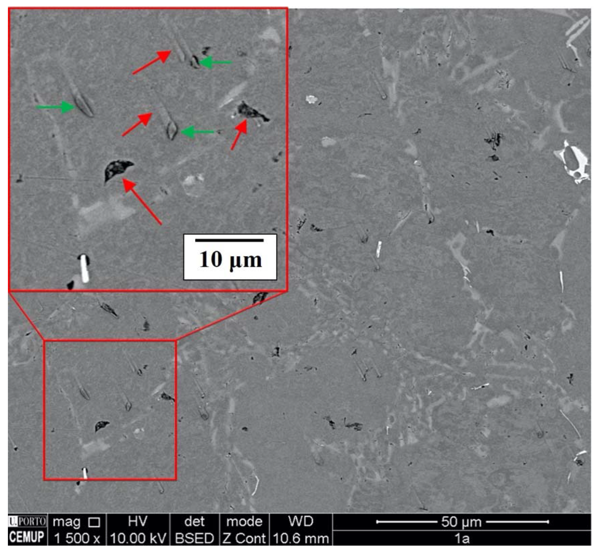
3.2. MMC Characterization

Figure 6 shows a representation of particle size and distribution in the different areas of the testing conditions (according to Figure 4). It may be observed that the different experimental protocols significantly influenced the overall integration of the m-SiCp within the A356 alloy. However, it is a common feature that ultrasonic treatment successfully degassed the melts (average of ρ = 2.64 ± 0.01 g/cm3) for all samples, and no significant porosity from melt treatment was observed.
m-SiCp size and distribution within the different fields in the tested samples were determined by image analysis (Figure 7). As evidenced, the approach in Condition 1 displayed lower values of m-SiCp size and density. It is hypothesized that the addition of particles after alloy melting promotes their decantation, especially in heavier particles. In this condition, the particles travel to the bottom of the crucible before the application of the US treatment and sediment. After their concentration in the lower part of the melt, they tended to re-agglomerate and the US excitation was only able to disperse light (i.e., lower sized) m-SiCp. This is evidenced by the observation of a well consolidated volume of m-SiCp in the crucible after melt pouring, the balance between the low values of particle size in both areas (Figure 6a and Figure 7a), and higher particle density in the bottom area (Figure 6b and Figure 7b).
According to the results in Figure 6 and Figure 7, it may be concluded that this issue can be addressed by the addition of particles in the semisolid state (Conditions 2 and 3, Table 2). As reported, the present approach is able to significantly increase the distribution of m-SiCp with coarse size and density in the alloy. The introduction of particles in the semi-solid state derive from MMC rheocasting techniques [35]. Due to the success of the integration of particles by these techniques, there has been a recent resurgence of current MMC casting techniques (e.g., stir casting) to integrate particles in the semi-solid state (e.g., [36,37]). It is hypothesized that the controllable viscosity in isothermal viscosity slurries promotes particle bonding with the matrix. The experimental data in this work corroborates this suggestion. These facts were introduced in the original manuscript [38,39].
However, it is highlighted in Figure 6c,d that the acoustic excitation of the US treatment alone was not able to promote a homogenized distribution of m-SiCp in terms of particle size. Figure 7a shows that the approach in Condition 2 had a lower concentration of larger m-SiCp in the bottom of the cast sample (area b). This means that, even though US power reaches the bottom of the crucible according to the PIV analysis in Figure 5, it struggles to displace larger particles and be active in the top of the crucible. Given that the material solidification in the bottom cast is initially composed by the melt in the top of the crucible, it has lower particle volume fraction. The higher distribution density of thinner m-SiCp in the middle section (area a, Figure 6c) also attests to this hypothesis.
Condition 3 is an optimized approach of the latter, in which mechanical stirring was used to promote the displacement and dispersion of coarser m-SiCp within the melt. In this case, it is proven by Figure 7a that this method is able to address coarse particle sedimentation, given that the mean particle size in the middle section (area a) is higher than the bottom section (area b). Additionally, this last method was able to generate a more elevated and homogenous density of particles within the tested areas (Figure 7b). These facts can also be observed in Figure 6e,f. It can also be emphasized that there were no traces of m-SiCp in the crucible after melt pouring (i.e., overall, the particles were diluted within the melt in that particular moment).
SEM analysis revealed that, especially in Condition 1 (Position 1b), there were defects within the α-Al grain, which could be observed in Figure 8a. While the EDS in Figure 8b identified Z1 as a m-SiCp, EDS tests in the identified defects (Z2 and Z3, Figure 8c,d) showed a profile that matched the α-Al matrix (Z4, Figure 8e). Thus, it can be seen that these defects are in fact cavities.
While initially this issue could be attributed to the gas entrapment in the melt, it is known that US melt treatment is a very effective degassing process. Furthermore, the shape of these cavities was not in accordance with the typical dissolved gas induced defect, as shown by their angular configuration. This means that these are indeed the sites that used to hold m-SiCp that were detached during the sample polishing process. In practical terms, this was already evidenced in the polishing process, in which samples from Condition 1 were more prone to polishing defects than the samples from Conditions 2 and 3 such as the tracking marks in the sample surface detailed in Figure 9. Such evidence implies that during the polishing process, hard m-SiCp particles were detached and scratched the soft α-Al matrix. Overall, this effect suggests that the introduction of m-SiCp after alloy melting (Condition 1) lowers their wettability relative to the melt.
Even though the overall particle density in Conditions 2 and 3 were significantly higher (Figure 7b), these issues were not observed. In fact, according to Figure 10, it is suggested that the m-SiCp themselves were well integrated and bonded to the α-Al matrix. This means that the addition of particles in the semi-solid state was able to enhance the wettability of the m-SiCp within the melt, which by itself can be considered a significant factor in preventing particle sedimentation, as shown by the results in Figure 6 and Figure 7. In fact, the benefit of ultrasonic melt excitation on the wettability of hard ceramic particles has already been predicted [40,41], while the presented results seem to corroborate this hypothesis.

4. Conclusions

The correlation of the studied variables allows for the establishment of some fundamental guidelines for the introduction of m-SiCp to promote a homogenous distribution of reinforcement particles in Al melt alloys. It has been proven that ultrasonic processing is able to generate the fluid displacement (i.e., mixing and distribution of particles within a fluid), however, the route used to introduce m-SiCp in the melt is fundamental to obtain successful melt processing and particle integration.
According to the results, it can be concluded that the addition of m-SiCp in the semi-solid state generates a better dispersion and volume fractions. This is in accordance with stir- and rheocasting approaches, suggesting that this method prevents fast particle sedimentation in the melt and cast sample. It is hypothesized that this may be attributed to an increase in wettability, evidenced by the integration and lack of particle detachment when the particles were added to the semi-solid alloy.
Particle image velocimetry showed that ultrasonic excitation is able to disperse m-SiCp, however, alone it may not be able to displace coarser particles. This was evidenced by the higher concentration of these particles at the bottom of the cast samples without mechanical stirring. This issue was addressed by performing simultaneous ultrasonic melt treatment and mechanical stirring, the results of which showed a homogenized distribution of particle density and size along the cast specimen.

Author Contributions

Conceptualization, V.H.C. and H.P.; Methodology, V.H.C., H.P., J.G., and S.D.T.; Validation, H.P.; Formal analysis, V.H.C. and J.G.; Resources, J.C.T. and F.V.B.; Data curation, V.H.C. and S.D.T.; Writing—original draft preparation, V.H.C. and H.P.; Writing—review and editing V.H.C., H.P., J.G., and S.D.T. All authors have read and agreed to the published version of the manuscript.

Funding

This work was supported by PTDC/EMEEME/30967/2017 and NORTE-0145-FEDER-030967, co-financed by the European Regional Development Fund (ERDF), the Operational Program for Competitiveness and Internationalization (COMPETE 2020), under Portugal 2020, and by the Fundação para a Ciência e a Tecnologia—FCT I.P. national funds. Additionally, this work was supported by the Portuguese FCT under the reference project UIDB/04436/2020 and the Stimulus of Scientific Employment Application CEECIND/03991/2017.

Conflicts of Interest

Authors declare no conflicts of interest.

References

  1. Koli, D.K.; Agnihotri, G.; Purohit, R. Advanced Aluminium Matrix Composites: The Critical Need of Automotive and Aerospace Engineering Fields. Mater. Today Proc. 2015, 2, 3032–3041. [Google Scholar] [CrossRef]
  2. Benedyk, J.C. 3—Aluminum Alloys for Lightweight Automotive Structures. In Materials, Design and Manufacturing for Lightweight Vehicles; Mallick, P.K., Ed.; Woodhead Publishing: Cambridge, UK, 2010; pp. 79–113. ISBN 978-1-84569-463-0. [Google Scholar]
  3. Peter, I.; Rosso, M. Light Alloys—From Traditional to Innovative Technologies. In New Trends in Alloy Development, Characterization and Application; Ahmad, Z., Ed.; IntechOpen: Rijeka, Croatia, 2015; pp. 3–37. [Google Scholar]
  4. Bodunrin, M.O.; Alaneme, K.K.; Chown, L.H. Aluminium matrix hybrid composites: A review of reinforcement philosophies; mechanical, corrosion and tribological characteristics. J. Mater. Res. Technol. 2015, 4, 434–445. [Google Scholar] [CrossRef] [Green Version]
  5. Li, W.; Yang, Y.; Li, M.; Liu, J.; Cai, D.; Wei, Q.; Yan, C.; Shi, Y. Enhanced mechanical property with refined microstructure of a novel γ-TiAl/TiB2 metal matrix composite (MMC) processed via hot isostatic press. Mater. Des. 2018, 144, 57–66. [Google Scholar] [CrossRef]
  6. Yuan, Z.; Tian, W.; Tian, W.; Li, F.; Fu, Q.; Hu, Y.; Wang, X. Microstructure and properties of high-entropy alloy reinforced aluminum matrix composites by spark plasma sintering. J. Alloys Compd. 2019, 806, 901–908. [Google Scholar] [CrossRef]
  7. Alizadeh, A.; Taheri-Nassaj, E.; Hajizamani, M. Hot extrusion process effect on mechanical behavior of stir cast Al based composites reinforced with mechanically milled B4C nanoparticles. J. Mater. Sci. Technol. 2011, 27, 1113–1119. [Google Scholar] [CrossRef]
  8. Hanizam, H.; Salleh, M.S.; Omar, M.Z.; Sulong, A.B. Optimisation of mechanical stir casting parameters for fabrication of carbon nanotubes–aluminium alloy composite through Taguchi method. J. Mater. Res. Technol. 2019, 8, 2223–2231. [Google Scholar] [CrossRef]
  9. Kumar, V.A.; Anil, M.P.; Rajesh, G.L.; Hiremath, V.; Auradi, V. Tensile and Compression Behaviour of Boron Carbide Reinforced 6061Al MMC’s processed through Conventional Melt Stirring. Mater. Today Proc. 2018, 5, 16141–16145. [Google Scholar] [CrossRef]
  10. Czerwinski, F. Modern Aspects of Liquid Metal Engineering. Metall. Mater. Trans. B 2017, 48, 367–393. [Google Scholar] [CrossRef]
  11. Czerwinski, F.; Birsan, G. Gas-Enhanced Ultra-High Shear Mixing: A Concept and Applications. Metall. Mater. Trans. B 2017, 48, 983–992. [Google Scholar] [CrossRef]
  12. Czerwinski, F.; Benkel, F.; Birsan, G. Gas-Enhanced Ultrahigh-Shear Mixing: An Application to Molten Aluminum Alloys. Metall. Mater. Trans. B 2020, 48, 1–9. [Google Scholar] [CrossRef]
  13. Poovazhagan, L.; Kalaichelvan, K.; Rajadurai, A.; Senthilvelan, V. Characterization of Hybrid Silicon Carbide and Boron Carbide Nanoparticles-Reinforced Aluminum Alloy Composites. Procedia Eng. 2013, 64, 681–689. [Google Scholar] [CrossRef] [Green Version]
  14. Meti, V.K.V.; Konaraddi, R.; Siddhalingeshwar, I.G. Mechanical and Tribological Properties of AA7075 Based MMC Processed through Ultrasound Assisted Casting Technique. Mater. Today Proc. 2018, 5, 25677–25687. [Google Scholar] [CrossRef]
  15. Li, X.; Yang, Y.; Cheng, X. Ultrasonic-assisted fabrication of metal matrix nanocomposites. J. Mater. Sci. 2004, 39, 3211–3212. [Google Scholar] [CrossRef]
  16. Thandalam, S.K.; Ramanathan, S.; Sundarrajan, S. Synthesis, microstructural and mechanical properties of ex situ zircon particles (ZrSiO4) reinforced Metal Matrix Composites (MMCs): A review. J. Mater. Res. Technol. 2015, 4, 333–347. [Google Scholar] [CrossRef] [Green Version]
  17. Rahman, M.H.; Rashed, H.M.M.A. Characterization of Silicon Carbide Reinforced Aluminum Matrix Composites. Procedia Eng. 2014, 90, 103–109. [Google Scholar] [CrossRef] [Green Version]
  18. Pramanik, A.; Islam, M.N.; Davies, I.J.; Boswell, B.; Dong, Y.; Basak, A.K.; Uddin, M.S.; Dixit, A.R.; Chattopadhyaya, S. Contribution of machining to the fatigue behaviour of metal matrix composites (MMCs) of varying reinforcement size. Int. J. Fatigue 2017, 102, 9–17. [Google Scholar] [CrossRef] [Green Version]
  19. Suresh, S.; Moorthi, N.S.V. Process Development in Stir Casting and Investigation on Microstructures and Wear Behavior of TiB2 on Al6061 MMC. Procedia Eng. 2013, 64, 1183–1190. [Google Scholar] [CrossRef] [Green Version]
  20. Hashim, J.; Looney, L.; Hashmi, M.S.J. The wettability of SiC particles by molten aluminium alloy. J. Mater. Proc. Technol. 2001, 119, 324–328. [Google Scholar] [CrossRef]
  21. Akbari, M.K.; Shirvanimoghaddam, K.; Hai, Z.; Zhuiykov, S.; Khayyam, H. Al-TiB2 micro/nanocomposites: Particle capture investigations, strengthening mechanisms and mathematical modelling of mechanical properties. Mater. Sci. Eng. A 2017, 682, 98–106. [Google Scholar] [CrossRef]
  22. Puga, H.; Carneiro, V.H.; Barbosa, J.; Soares, D. Effect of grain and secondary phase morphologies in the mechanical and damping behavior of Al7075 alloys. Metals Mater. Int. 2016, 22, 863–871. [Google Scholar] [CrossRef]
  23. Puga, H.; Barbosa, J.; Azevedo, T.; Ribeiro, S.; Alves, J.L. Low pressure sand casting of ultrasonically degassed AlSi7Mg0.3 alloy: Modelling and experimental validation of mould filling. Mater. Des. 2016, 94, 384–391. [Google Scholar] [CrossRef]
  24. Puga, H.; Carneiro, V.; Barbosa, J.; Vieira, V. Effect of Ultrasonic Treatment in the Static and Dynamic Mechanical Behavior of AZ91D Mg Alloy. Metals 2015, 5, 2210–2221. [Google Scholar] [CrossRef] [Green Version]
  25. Carneiro, V.H.; Puga, H. T6 Heat Treatment Impact on the Random Frequency Vibration Stress of Al–Si–Mg Alloys. Metals Mater. Int. 2019, 25, 880–887. [Google Scholar] [CrossRef]
  26. Ahmadpour, A.; Raiszadeh, R.; Doostmohammadi, H. Effect of stirring on behaviour of double oxide film defects in A356 aluminium melt. Int. J. Cast Metals Res. 2014, 27, 221–229. [Google Scholar] [CrossRef]
  27. Dispinar, D.; Akhtar, S.; Nordmark, A.; Di Sabatino, M.; Arnberg, L. Degassing, hydrogen and porosity phenomena in A356. Mater. Sci. Eng. A 2010, 527, 3719–3725. [Google Scholar] [CrossRef]
  28. Yamamoto, T.; Kato, W.; Kamorov, S.V.; Ishiwata, Y. Investigation on the Surface Vortex Formation During Mechanical Stirring with an Axial-Flow Impeller Used in an Aluminum Process. Metall. Mater. Trans. B 2019, 50, 2547–2556. [Google Scholar] [CrossRef]
  29. Kojima, Y.; Asakura, Y.; Sugiyama, G.; Koda, S. The effects of acoustic flow and mechanical flow on the sonochemical efficiency in a rectangular sonochemical reactor. Ultrason. Sonochem. 2010, 17, 978–984. [Google Scholar] [CrossRef]
  30. Trujillo, F.J.; Knoerzer, K. A computational modeling approach of the jet-like acoustic streaming and heat generation induced by low frequency high power ultrasonic horn reactors. Ultrason. Sonochem. 2011, 18, 1263–1273. [Google Scholar] [CrossRef]
  31. Mettin, R.; Akhatov, I.; Parlitz, U.; Ohl, C.D.; Lauterborn, W. Bjerknes forces between small cavitation bubbles in a strong acoustic field. Phys. Rev. E 1997, 56, 2924–2931. [Google Scholar] [CrossRef] [Green Version]
  32. Shen, Y.; Dimotakis, P.E. The Influence of Surface Cavitation on Hydrodynamic Forces. In Proceedings of the 22nd American Towing Tank Conference, St Jones, NL, Canada, 8–11 August 1989. [Google Scholar]
  33. Schenker, M.C.; Pourquié, M.J.B.M.; Eskin, D.G.; Boersma, B.J. PIV quantification of the flow induced by an ultrasonic horn and numerical modeling of the flow and related processing times. Ultrason. Sonochem. 2013, 20, 502–509. [Google Scholar] [CrossRef]
  34. Fang, Y.; Yamamoto, T.; Komarov, S. Cavitation and acoustic streaming generated by different sonotrode tips. Ultrason. Sonochem. 2018, 48, 79–87. [Google Scholar] [CrossRef] [PubMed]
  35. Jiang, J.; Xiao, G.; Che, C.; Wang, Y. Microstructure, Mechanical Properties and Wear Behavior of the Rheoformed 2024 Aluminum Matrix Composite Component Reinforced by Al2O3 Nanoparticles. Metals 2018, 8, 460. [Google Scholar] [CrossRef] [Green Version]
  36. Ramnath, V.; Elanchezhian, C.; Jaivignesh, M.; Rajesh, S.; Parswajinan, C.; Ghias, A.S.A. Evaluation of mechanical properties of aluminium alloy–alumina–boron carbide metal matrix composites. Mater. Des. 2014, 58, 332–338. [Google Scholar] [CrossRef]
  37. Huand, Q.; He, R.; Wang, C.; Tang, X. Microstructure, Corrosion and Mechanical Properties of TiC Particles/Al-5Mg Composite Fillers for Tungsten Arc Welding of 5083 Aluminum Alloy. Materials 2019, 12, 3029. [Google Scholar]
  38. Kim, G.-Y. Fabrication of Metal Matrix Composite by Semi-Solid Powder Processing. Ph.D. Thesis, Iowa State University, Ames, ID, USA, 2011. [Google Scholar]
  39. Malekan, A.; Emamy, M.; Rassizadehghani, J.; Malekan, M.; Huand, Q.; He, R.; Wang, C.; Tang, X. Effect of Isothermal Holding on Semisolid Microstructure of Al–Mg2Si Composites. Int. Sch. Res. Netw. 2012, 2012, 631096. [Google Scholar] [CrossRef]
  40. Yang, C.; Liu, Z.; Zheng, Q.; Cao, Y.; Dai, X.; Sun, L.; Zhao, J.; Xing, J.; Han, Q. Ultrasound assisted in-situ casting technique for synthesizing small-sized blocky Al3Ti particles reinforced A356 matrix composites with improved mechanical properties. J. Alloys Compd. 2018, 747, 580–590. [Google Scholar] [CrossRef]
  41. Tsunekawa, Y.; Suzuki, H.; Genma, Y. Application of ultrasonic vibration to in situ MMC process by electromagnetic melt stirring. Mater. Des. 2001, 22, 467–472. [Google Scholar] [CrossRef]
Figure 1. Particle image velocimetry (PIV): (1) US MMM transducer; (2) CCD camera, Hisense Zyla; (3) Double pulse laser; (4) illuminated water with m-SiCp tracer particles.
Metals 10 00610 g001
Figure 2. Schematics of (a) experimental apparatus: (1) US transducer; (2) and (3) support structure; (4) electric resistance furnace; (5) thermocouple controller; (6) US MMM generator; and (b) mechanical stirring process.
Metals 10 00610 g002
Figure 3. m-SiCp characterization: (a) Scanning electron microscope (SEM) imaging detailing size and morphology; (b) size distribution of m-SiCp.
Metals 10 00610 g003
Figure 4. Sample characterization of cast specimens and samples for microstructural characterization.
Metals 10 00610 g004
Figure 5. Streaming vectors and average velocity amplitude measured with 2D particle image velocimetry (PIV) below the sonotrode tip at: (a) t = 16 ms; (b) t = 48 ms; and (c) t = 80 ms.
Metals 10 00610 g005
Figure 6. Overview of m-SiCp distribution by SEM according to Figure 4. Condition 1: (a,b); Condition 2: (c,d); Condition 3: (e,f).
Metals 10 00610 g006
Figure 7. Results on m-SiCp (a) size and (b) distribution in different fields and testing conditions.
Metals 10 00610 g007
Figure 8. SEM characterization of the sample of Condition 1-Position (1b). (a) SEM micrograph; EDS in areas (b) Z1; (c) Z2; (d) Z3; and (e) Z4.
Metals 10 00610 g008
Figure 9. Detail of the scratching of the α-Al matrix by detached m-SiCp (Condition 1-Position 1a).
Metals 10 00610 g009
Figure 10. Detail of particle bonding in the α-Al matrix. (a) Condition 3-Position 3b; (b) Condition 3-Position 3a.
Metals 10 00610 g010
Table 1. Composition of the A356 alloy by optical emission spectrometry.
ElementSiFeMgCuMnZnAl
wt%7.440.130.580.070.070.05Bal.
Table 2. Testing conditions.
ConditionProcessParameters
Time (min)Power (w)Frequency (kHz)
1m-SiCp added after melting + US1300 (30% of 1000)19.8 ± 0.15
2m-SiCp added in semisolid state + US1
3m-SiCp added in semisolid state + US + Mechanical stirring2

