Bi-Material Micro-Part of Stainless Steel and Zirconia by Two-Component Micro-Powder Injection Molding: Rheological Properties and Solvent Debinding Behavior


Abstract

1. Introduction
2. Experimental
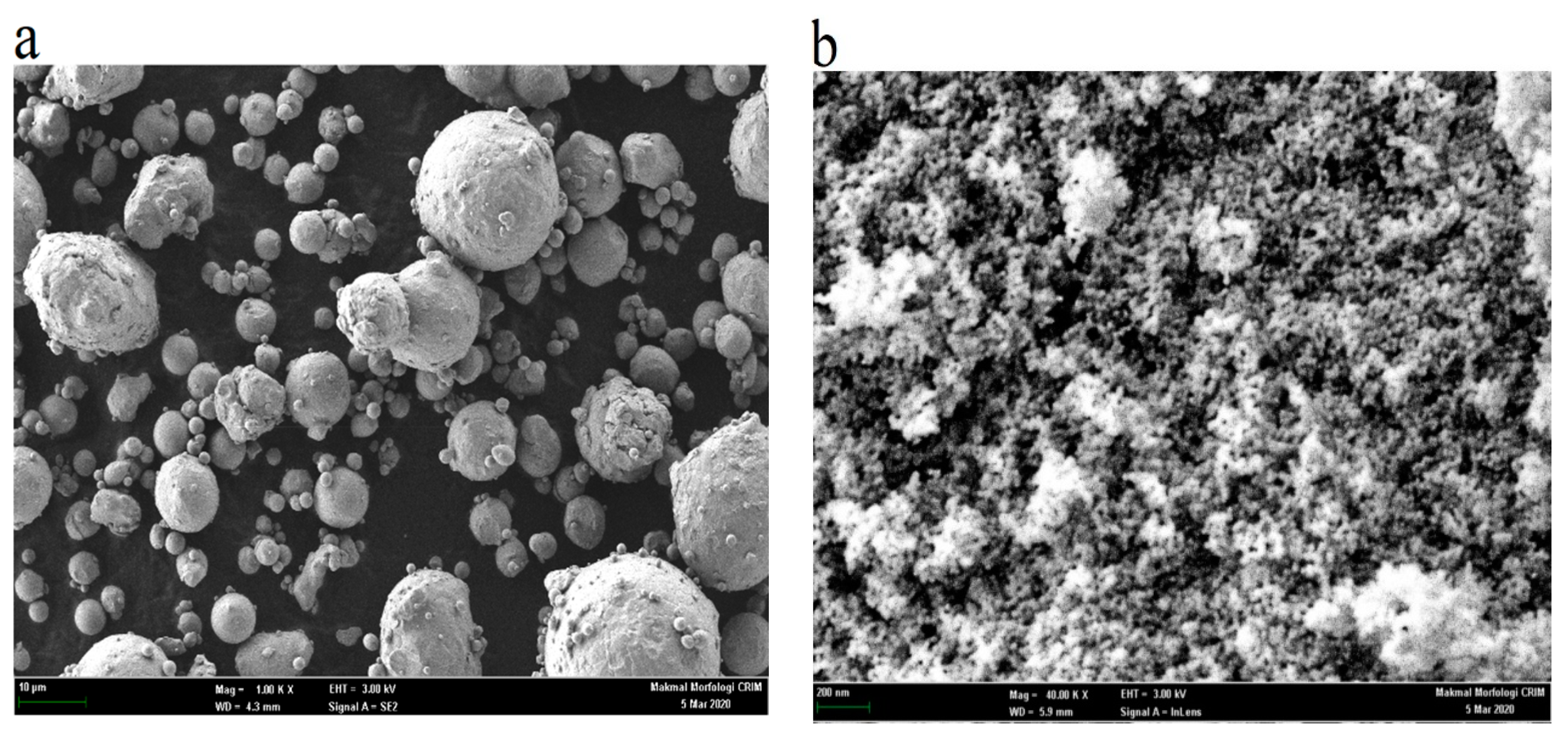
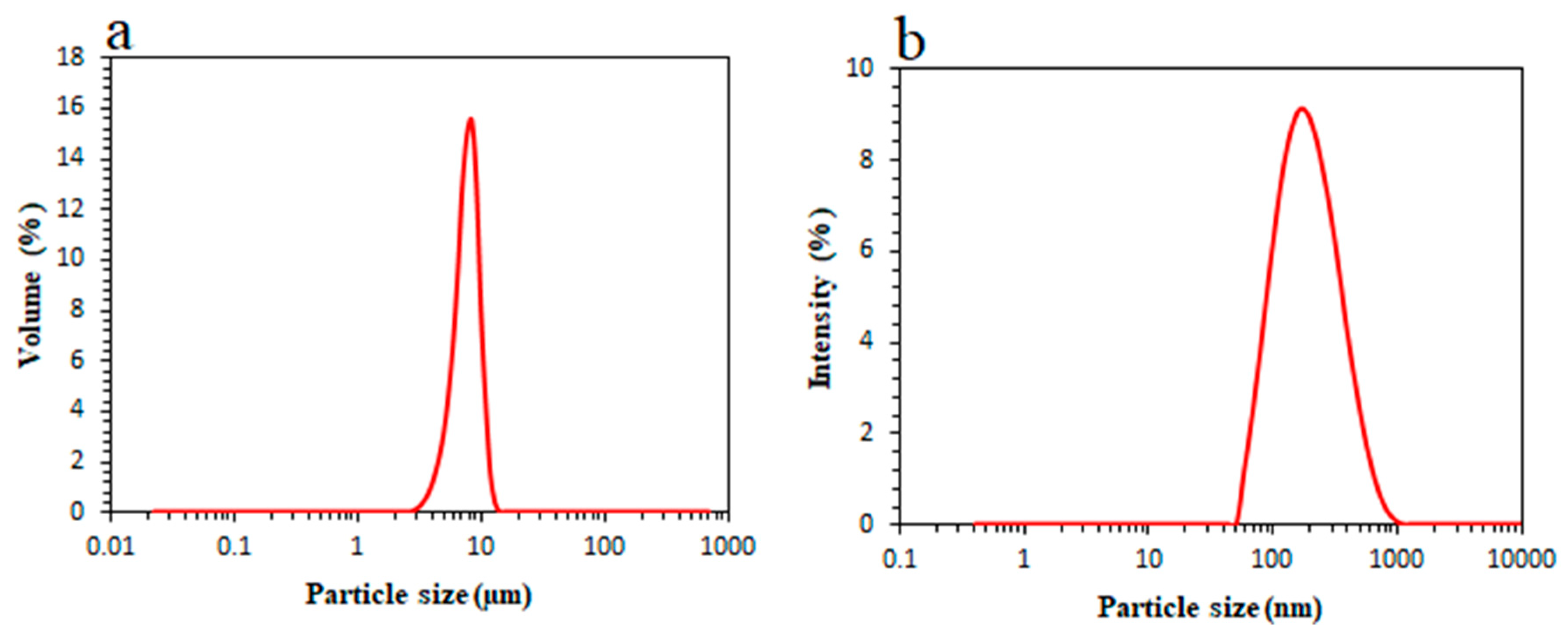
2.1. Materials
2.2. Experimental Procedures
2.2.1. Mixing
2.2.2. Rheological Analysis
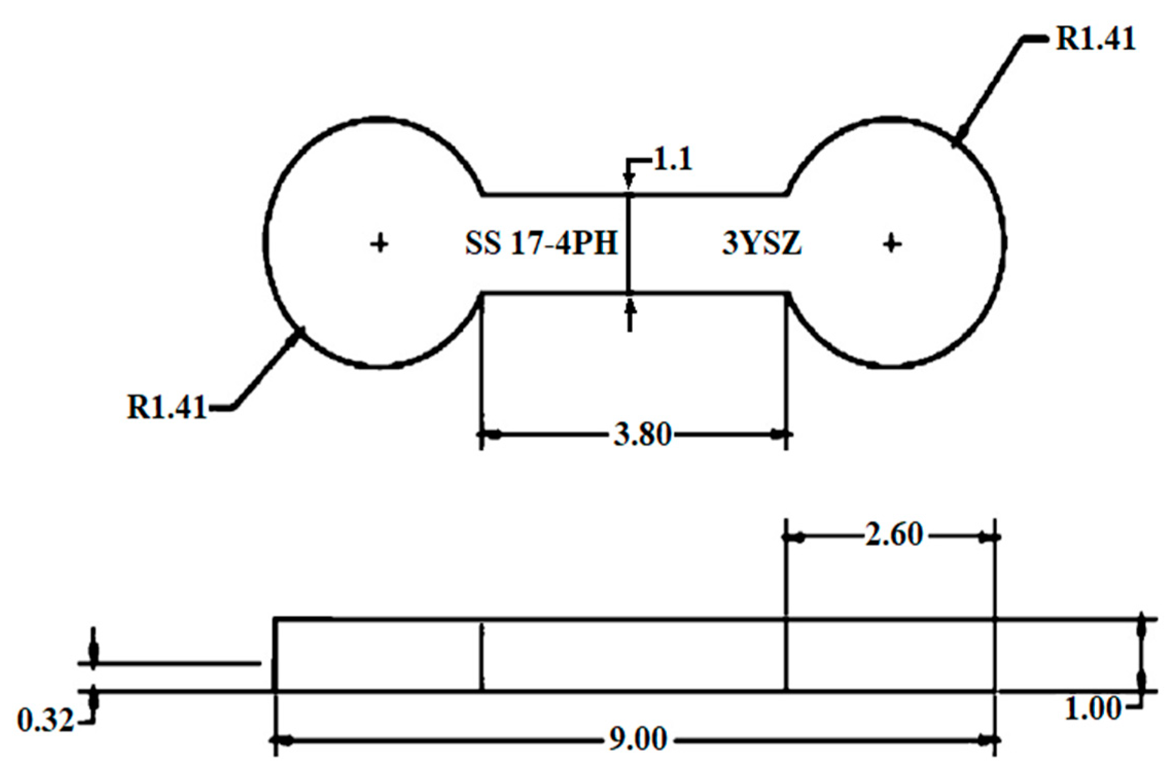
2.2.3. Bi-Material Micro-Powder Injection Molding
2.2.4. Solvent Debinding Process
3. Results and Discussion
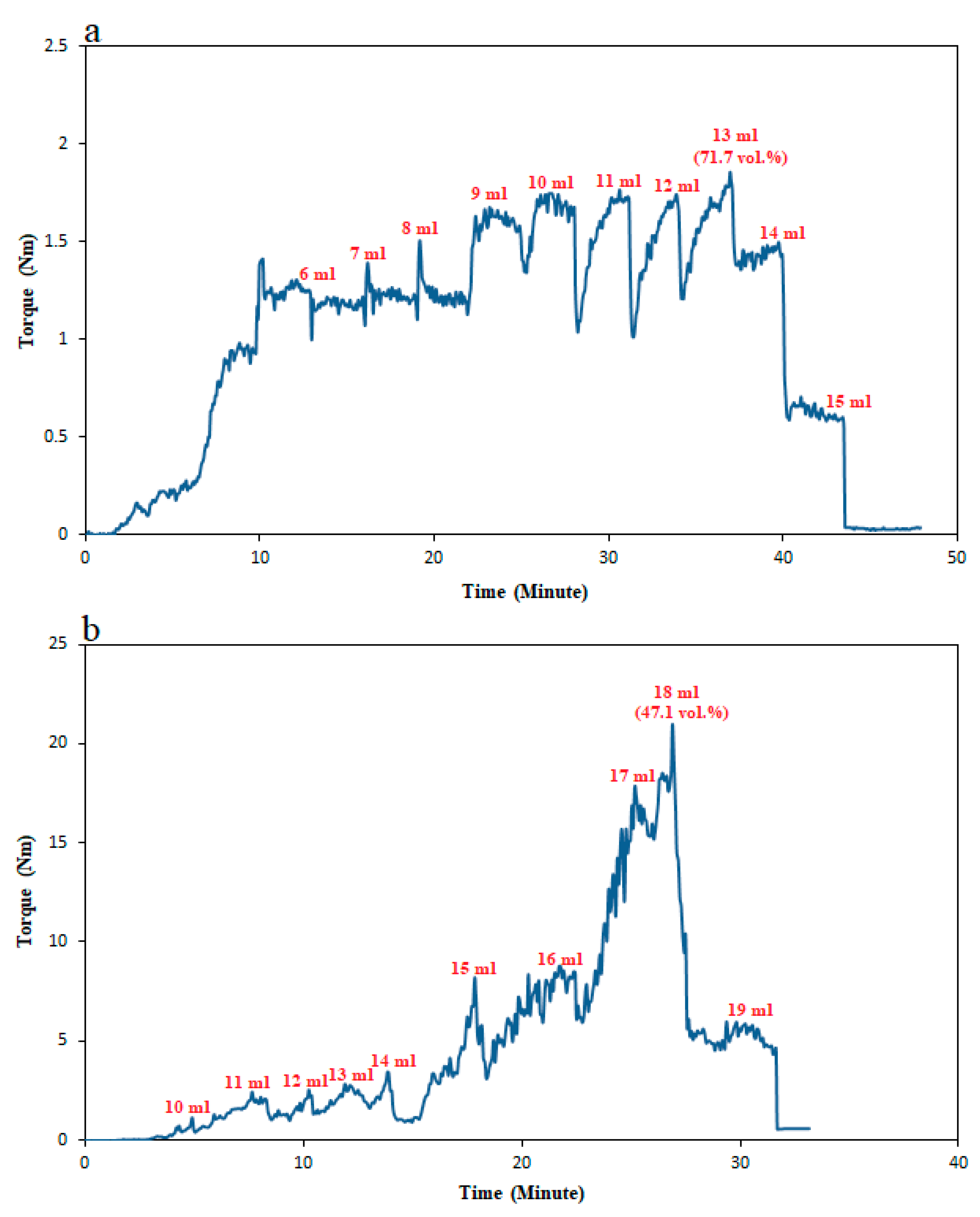
3.1. Optimal Powder Loading
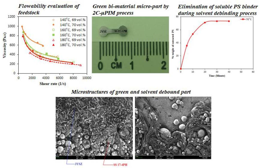
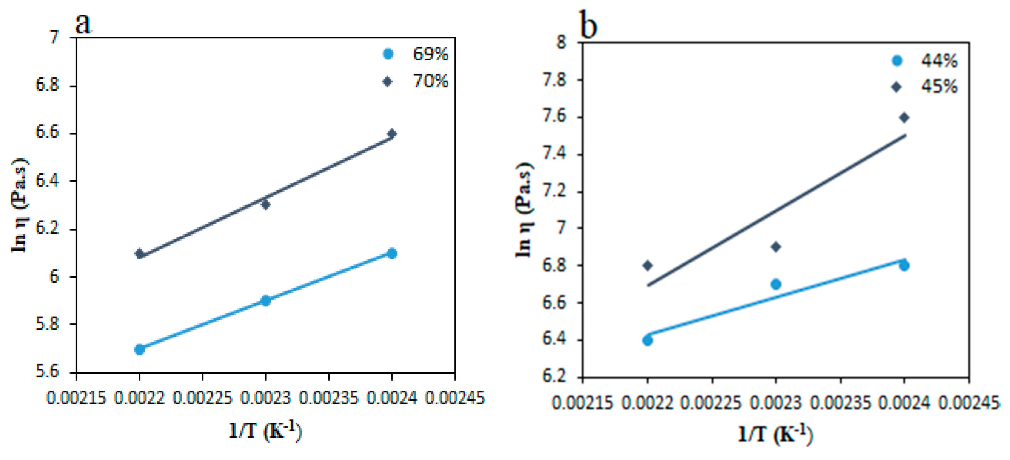
3.2. Rheology
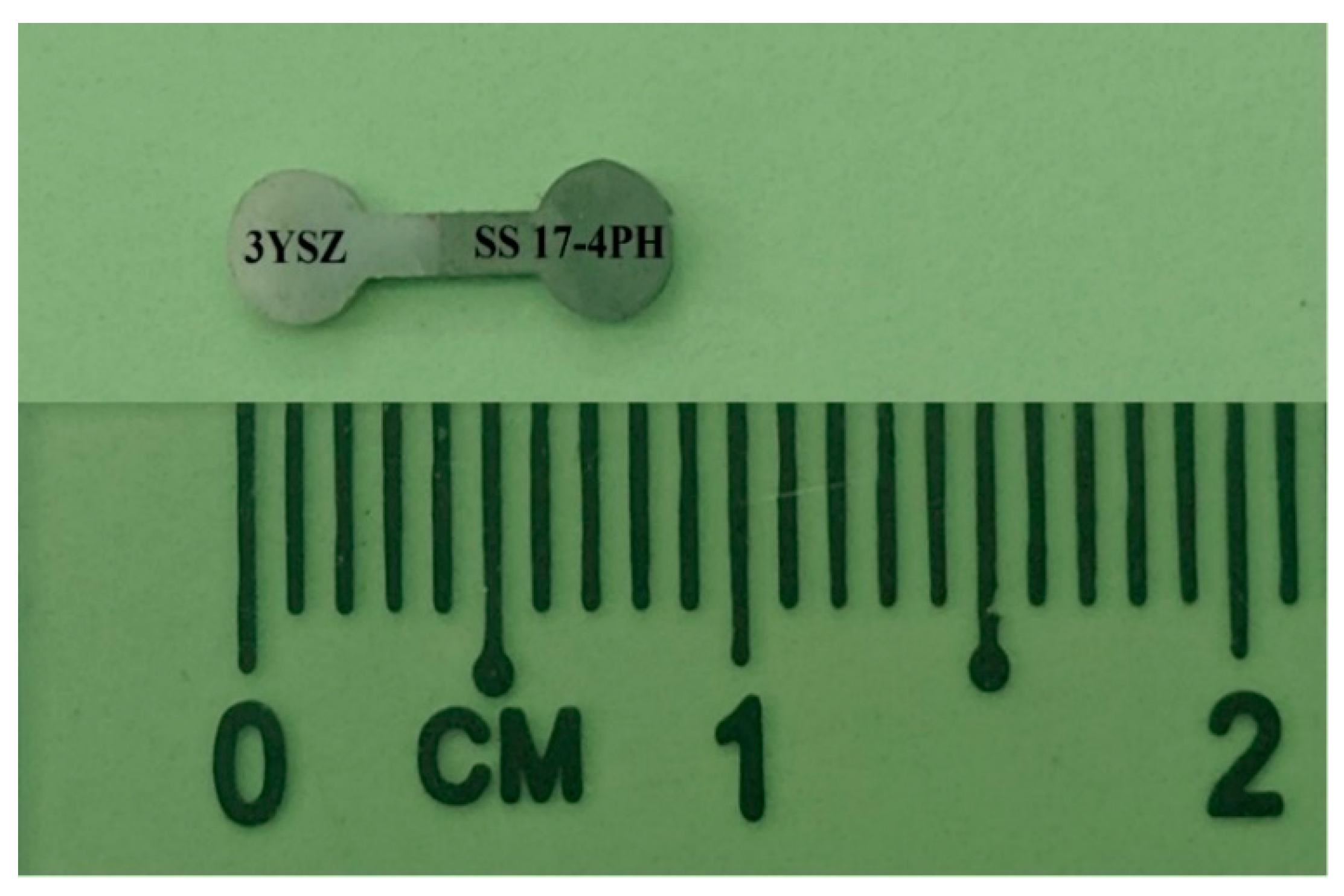
3.3. Injection Molding
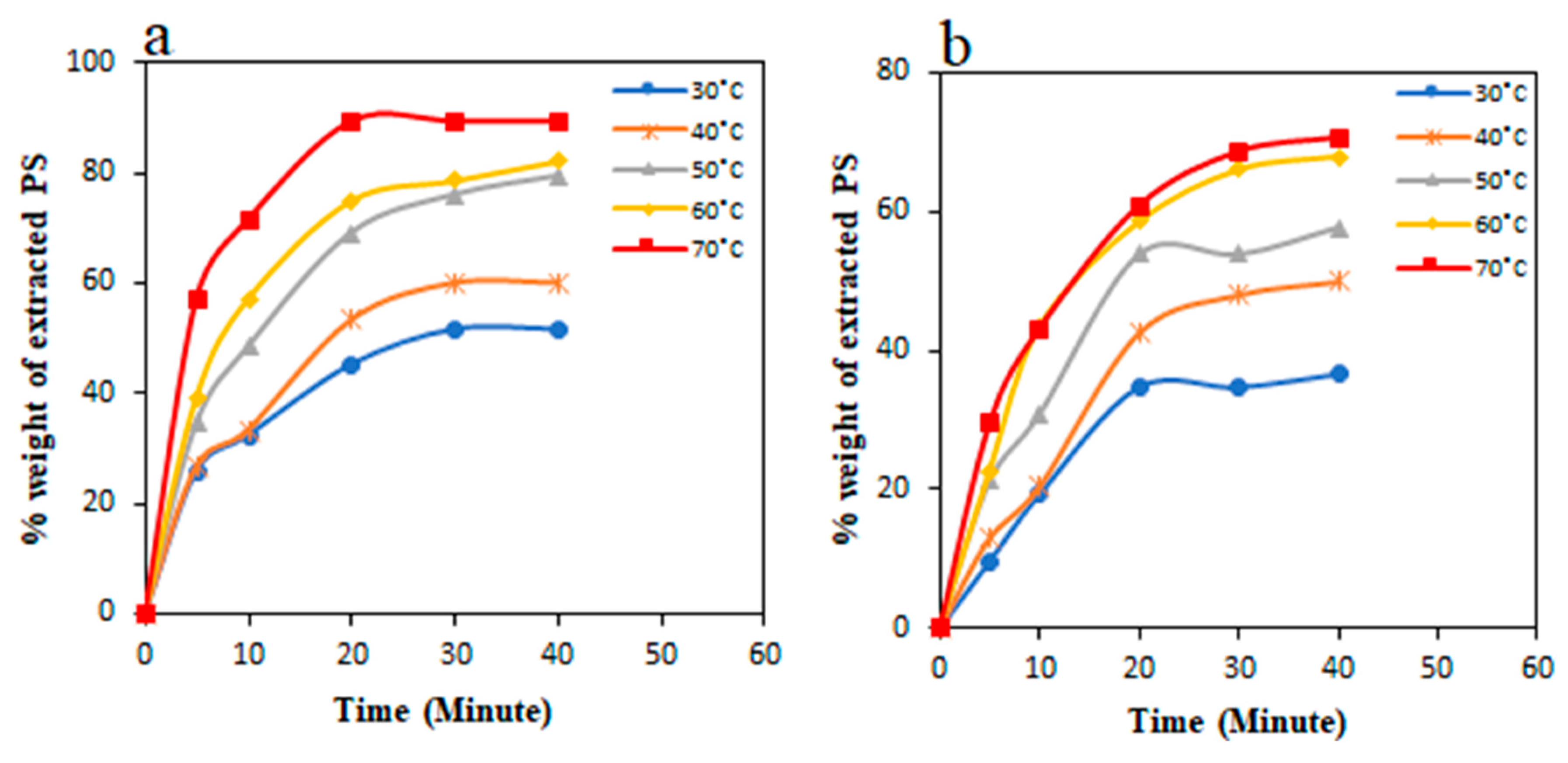
3.4. Solvent Debinding
4. Conclusions
Author Contributions
Funding
Acknowledgments
Conflicts of Interest
References
- Imgrund, P.; Rota, A.; Wiegmann, M. Getting better bonding at tiny interfaces. Met. Powder Rep. 2007, 62, 31–34. [Google Scholar] [CrossRef]
- Ruh, A.; Piotter, V.; Plewa, K.; Ritzhaupt-Kleissl, H.-J.; Hausselt, J. Development of two-component micropowder injection molding (2C-MicroPIM)—process development. Int. J. Appl. Ceram. Technol. 2011, 8, 610–616. [Google Scholar] [CrossRef]
- Checot-Moinard, D.; Rigollet, C.; Lourdin, P. Powder injection moulding PIM of feedstock based on hydrosoluble binder and submicronic powder to manufacture parts having micro-details. Powder Technol. 2011, 208, 472–479. [Google Scholar] [CrossRef]
- Escobar, C.F.; Santos, L.A.D. New eco-friendly binder based on natural rubber for ceramic injection molding process. J. Eur. Ceram. Soc. 2015, 35, 3567–3575. [Google Scholar] [CrossRef]
- German, R.M.; Bose, A. Injection Molding of Metals and Ceramics; Metal Powder Industries Federation: Princeton, NJ, USA, 1997. [Google Scholar]
- Lin, D.; Sanetrnik, D.; Cho, H.; Chung, S.T.; Kwon, Y.S.; Kate, K.H.; Hausnerova, B.; Atre, S.V.; Park, S.J. Rheological and thermal debinding properties of blended elemental Ti-6Al-4V powder injection molding feedstock. Powder Technol. 2017, 311, 357–363. [Google Scholar] [CrossRef]
- Emeka, U.B.; Sulong, A.B.; Muhamad, N.; Sajuri, Z. Solvent de-binding of Bi-material green component of two-component powder injection moulded stainless steel and zirconia. Int. J. Mech. Mechatron. Eng. 2018, 18, 96–104. [Google Scholar]
- Ramli, M.I.; Sulong, A.B.; Muhamad, N.; Muchtar, A.; Zakaria, M.Y. Effect of sintering on the microstructure and mechanical properties of alloy titanium-wollastonite composite fabricated by powder injection moulding process. Ceram. Int. 2019, 45, 11648–11653. [Google Scholar] [CrossRef]
- Emeka, U.B.; Sulong, A.B.; Muhamad, N.; Sajuri, Z.; Salleh, F. Two component injection molding of bi-material of stainless steel and yttria-stabilized zirconia – green part. J. Kejuruteraan 2017, 29, 49–55. [Google Scholar] [CrossRef]
- Tseng, W.J.; Hsu, C.-K. Cracking defect and porosity evolution during thermal debinding in ceramic injection moldings. Ceram. Int. 1999, 25, 461–466. [Google Scholar] [CrossRef]
- Raza, M.R.; Ahmad, F.; Omar, M.A.; German, R.M. Effects of cooling rate on mechanical properties and corrosion resistance of vacuum sintered powder injection molded 316L stainless steel. J. Mater. Process. Technol. 2012, 212, 164–170. [Google Scholar] [CrossRef]
- Choi, S.-H.; Kang, S.-D.; Kwon, Y.S.; Lim, S.G.; Cho, K.K.; Ahn, I.-S. The effect of sintering conditions on the properties of WC-10wt% Co PIM compacts. Res. Chem. Intermed. 2010, 36, 743–748. [Google Scholar] [CrossRef]
- Rajabi, J.; Zakaria, H.; Muhamad, N.; Sulong, A.B.; Fayyaz, A. Fabrication of miniature parts using nano-sized powders and an environmentally friendly binder through micro powder injection molding. Microsyst. Technol. 2015, 21, 1131–1136. [Google Scholar] [CrossRef]
- Torralba, J.M.; Hidalgo, J.; Jiménez-Morales, A. Powder injection moulding: Processing of small parts of complex shape. Int. J. Microstruct. Mater. Prop. 2013, 8, 87–96. [Google Scholar] [CrossRef]
- Aggarwal, G.; Smid, I.; Park, S.J.; German, R.M. Development of niobium powder injection molding. Part II: Debinding and sintering. Int. J. Refract. Met. Hard Mater. 2007, 25, 226–236. [Google Scholar] [CrossRef]
- Quinard, C.; Barriere, T.; Gelin, J.C. Development and property identification of 316L stainless steel feedstock for PIM and µPIM. Powder Technol. 2009, 190, 123–128. [Google Scholar] [CrossRef]
- Fayyaz, A.; Muhamad, N.; Sulong, A.B.; Yunn, H.S.; Amin, S.Y.M.; Rajabi, J. Micro-powder injection molding of cemented tungsten carbide: Feedstock preparation and properties. Ceram. Int. 2015, 41, 3605–3612. [Google Scholar] [CrossRef]
- Thavanayagam, G.; Pickering, K.L.; Swan, J.E.; Cao, P. Analysis of rheological behaviour of titanium feedstocks formulated with a water-soluble binder system for powder injection moulding. Powder Technol. 2015, 269, 227–232. [Google Scholar] [CrossRef]
- Li, Y.; Li, L.; Khalil, K.A. Effect of powder loading on metal injection molding stainless steels. J. Mater. Process. Technol. 2007, 183, 432–439. [Google Scholar] [CrossRef]
- Fayyaz, A.; Muhamad, N.; Sulong, A.B.; Rajabi, J.; Wong, Y.N. Fabrication of cemented tungsten carbide components by micro-powder injection moulding. J. Mater. Process. Technol. 2014, 214, 1436–1444. [Google Scholar] [CrossRef]
- Reddy, J.J.; Vijayakumar, M.; Tallapragada, R.M.R.; Ramakrishnan, P. Loading of solids in a liquid medium: Determination of CBVC by torque rheometry. J. Eur. Ceram. Soc. 1996, 16, 567–574. [Google Scholar] [CrossRef]
- Emeka, U.B.; Sulong, A.B.; Muhamad, N.; Sajuri, Z. The characterization and rheological investigation of materials for powder injection moulding. J. Mech. Eng. 2017, 3, 97–107. [Google Scholar]
- Foudzi, F.M.; Muhamad, N.; Sulong, A.B.; Zakaria, H. Yttria stabilized zirconia formed by micro ceramic injection molding: Rheological properties and debinding effects on the sintered part. Ceram. Int. 2013, 39, 2665–2674. [Google Scholar] [CrossRef]
- German, R.M. Sintering Theory and Practice; Wiley: New York, NY, USA, 1996. [Google Scholar]
- Luo, J.-S.; Yi, Z.-Z.; Xiao, B.; Gao, Y.; Xie, Z.-P.; Li, J.-B.; Huang, Y. Injection molding of ultra-fine zirconia (Y-TZP) powders. J. Ceram. Process. Res. 2006, 7, 14–19. [Google Scholar]
- He, J.; Shao, Z.; Khan, D.F.; Yin, H.; Elder, S.; Zheng, Q.; Qu, X. Investigation of inhomogeneity in powder injection molding of nano zirconia. Powder Technol. 2018, 328, 207–214. [Google Scholar] [CrossRef]
- Jabir, S.M.; Noorsyakirah, A.; Afian, O.M.; Nurazilah, M.Z.; Aswad, M.A.; Afiq, N.H.M.; Mazlan, M. Analysis of the rheological behavior of copper metal injection molding (MIM) feedstock. Procedia Chem. 2016, 19, 148–152. [Google Scholar] [CrossRef][Green Version]
- Choi, J.-P.; Park, J.-S.; Hong, E.-J.; Lee, W.-S.; Lee, J.-S. Analysis of the rheological behavior of Fe trimodal micro-nano powder feedstock in micro powder injection molding. Powder Technol. 2017, 319, 253–260. [Google Scholar] [CrossRef]
- Yang, W.-W.; Yang, K.-Y.; Hon, M.-H. Effects of PEG molecular weights on rheological behavior of alumina injection molding feedstocks. Mater. Chem. Phys. 2003, 78, 416–424. [Google Scholar] [CrossRef]
- Loebbecke, B.; Knitter, R.; Haußelt, J. Rheological properties of alumina feedstocks for the low-pressure injection moulding process. J. Eur. Ceram. Soc. 2009, 29, 1595–1602. [Google Scholar] [CrossRef]
- Huang, B.; Liang, S.; Qu, X. The rheology of metal injection molding. J. Mater. Process. Technol. 2003, 137, 132–137. [Google Scholar] [CrossRef]
- Heng, S.Y.; Raza, M.R.; Muhamad, N.; Sulong, A.B.; Fayyaz, A. Micro-powder injection molding (μPIM) of tungsten carbide. Int. J. Refract. Met. Hard Mater. 2014, 45, 189–195. [Google Scholar] [CrossRef]
- Ani, S.M.; Muchtar, A.; Muhamad, N.; Ghani, J.A. Fabrication of zirconia-toughened alumina parts by powder injection molding process: Optimized processing parameters. Ceram. Int. 2014, 40, 273–280. [Google Scholar] [CrossRef]


| Binders | Supplier | Chemical Formula | Meting Point (°C) | Density (g/cm3) | Content (wt.%) |
|---|---|---|---|---|---|
| PS | Sime Darby Kempas Sdn. Bhd., Malaysia | CH3(CH2)14COOH | 63 | 0.891 | 60 |
| LDPE | The Polyolefin Company (Singapore) Pte Ltd. | (C2H4) | 117.3 | 0.91 | 40 |
| Feedstocks | Optimal Powder Loadings (vol.%) | Temperature (°C) | Flow Behavior Index |
|---|---|---|---|
| SS 17-4PH | 69 | 140 | 0.672 |
| 160 | 0.498 | ||
| 180 | 0.457 | ||
| 70 | 140 | 0.742 | |
| 160 | 0.555 | ||
| 180 | 0.492 | ||
| 3YSZ | 44 | 140 | 0.534 |
| 160 | 0.514 | ||
| 180 | 0.467 | ||
| 45 | 140 | 0.612 | |
| 160 | 0.528 | ||
| 180 | 0.481 |
| Injection Parameters | Operating Process | |
|---|---|---|
| SS 17-4PH | 3YSZ | |
| Injection pressure | 10 bar | 10 bar |
| Compression pressure | 10 bar | 10 bar |
| Holding pressure | 10 bar | 10 bar |
| Melt temperature | 180 °C | 180 °C |
| Mold temperature | 45 °C | 65 °C |
| Injection time | 7 s | 7 s |
| Compression time | 7 s | 7 s |
| Holding time | 7 s | 7 s |
© 2020 by the authors. Licensee MDPI, Basel, Switzerland. This article is an open access article distributed under the terms and conditions of the Creative Commons Attribution (CC BY) license (http://creativecommons.org/licenses/by/4.0/).
Share and Cite
Basir, A.; Sulong, A.B.; Jamadon, N.H.; Muhamad, N. Bi-Material Micro-Part of Stainless Steel and Zirconia by Two-Component Micro-Powder Injection Molding: Rheological Properties and Solvent Debinding Behavior. Metals 2020, 10, 595. https://doi.org/10.3390/met10050595
Basir A, Sulong AB, Jamadon NH, Muhamad N. Bi-Material Micro-Part of Stainless Steel and Zirconia by Two-Component Micro-Powder Injection Molding: Rheological Properties and Solvent Debinding Behavior. Metals. 2020; 10(5):595. https://doi.org/10.3390/met10050595
Chicago/Turabian StyleBasir, Al, Abu Bakar Sulong, Nashrah Hani Jamadon, and Norhamidi Muhamad. 2020. "Bi-Material Micro-Part of Stainless Steel and Zirconia by Two-Component Micro-Powder Injection Molding: Rheological Properties and Solvent Debinding Behavior" Metals 10, no. 5: 595. https://doi.org/10.3390/met10050595
APA StyleBasir, A., Sulong, A. B., Jamadon, N. H., & Muhamad, N. (2020). Bi-Material Micro-Part of Stainless Steel and Zirconia by Two-Component Micro-Powder Injection Molding: Rheological Properties and Solvent Debinding Behavior. Metals, 10(5), 595. https://doi.org/10.3390/met10050595