Forming Complex Graded and Homogeneous Components by Joining Simple Presintered Parts of TRIP-Matrix Composite through Powder Forging


Abstract
1. Introduction
2. Materials and Methods
3. Results
4. Discussion
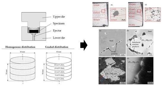
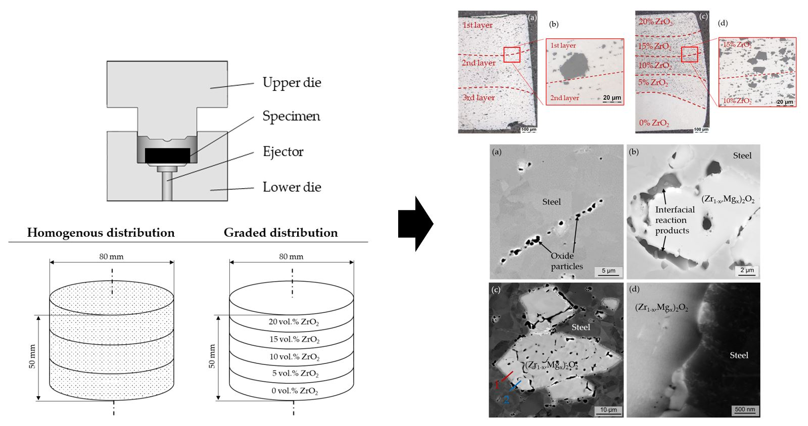
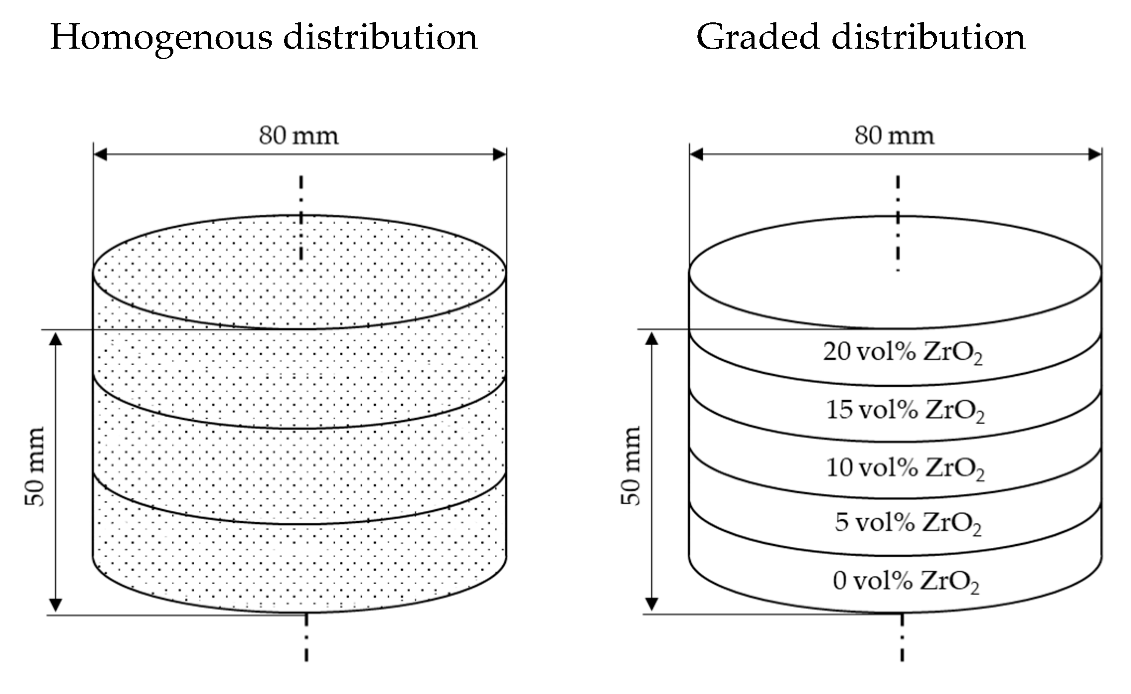
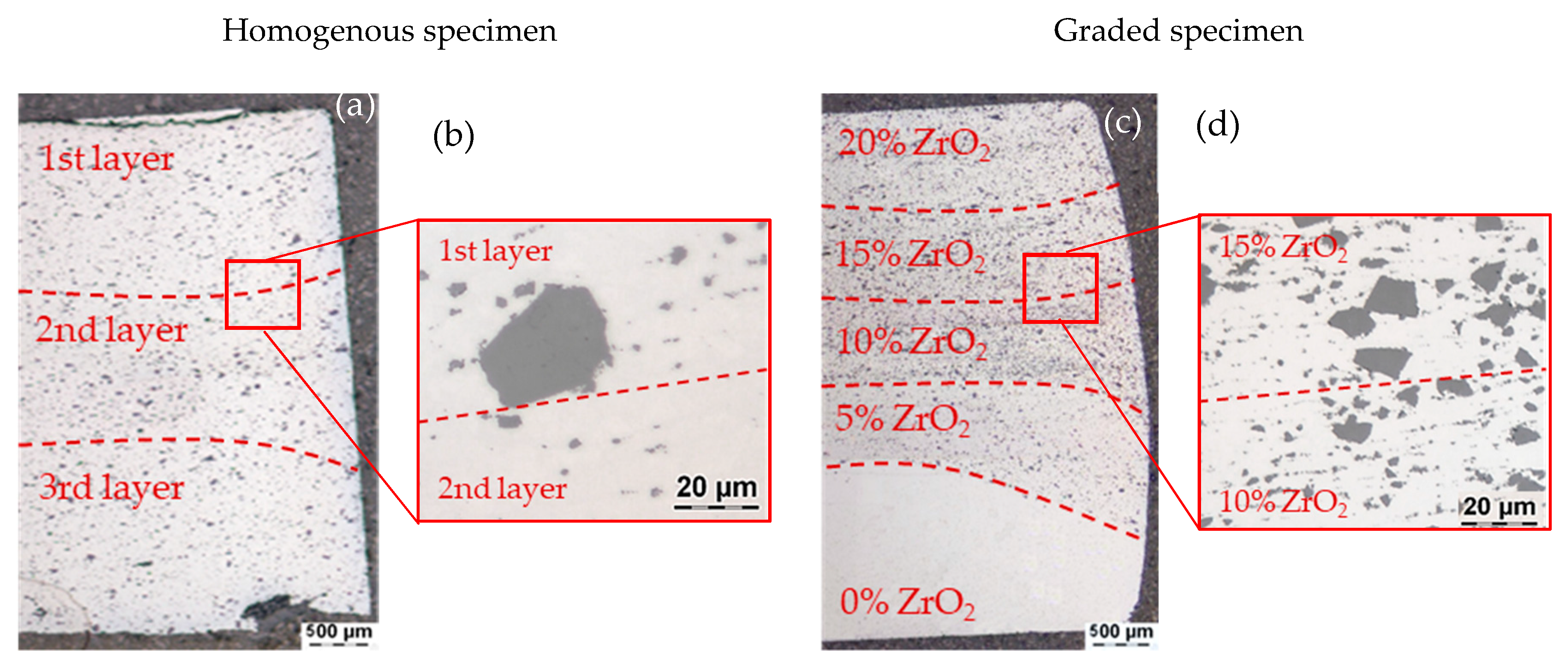
4.1. Light Microscopy Imaging
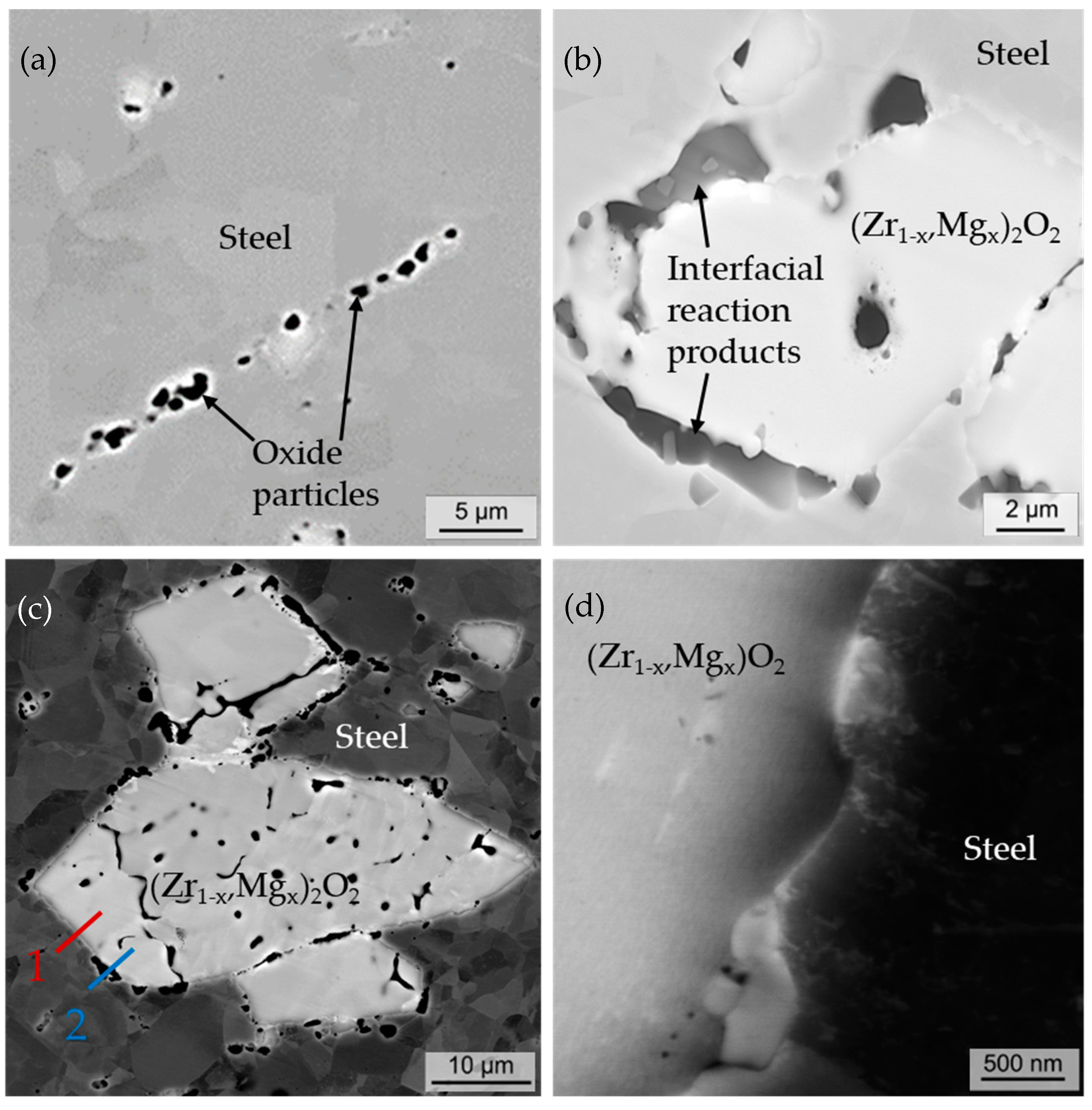
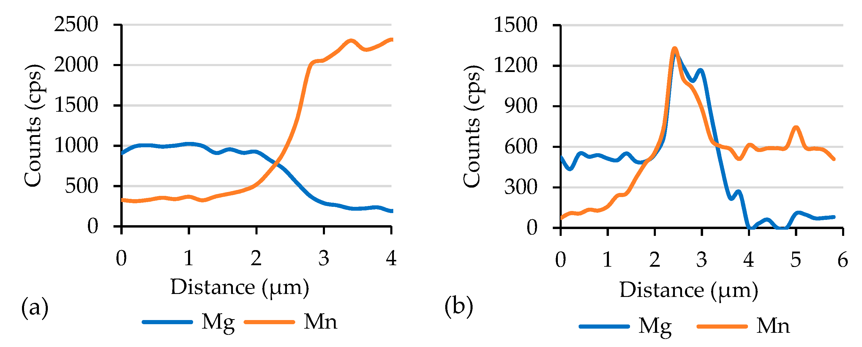
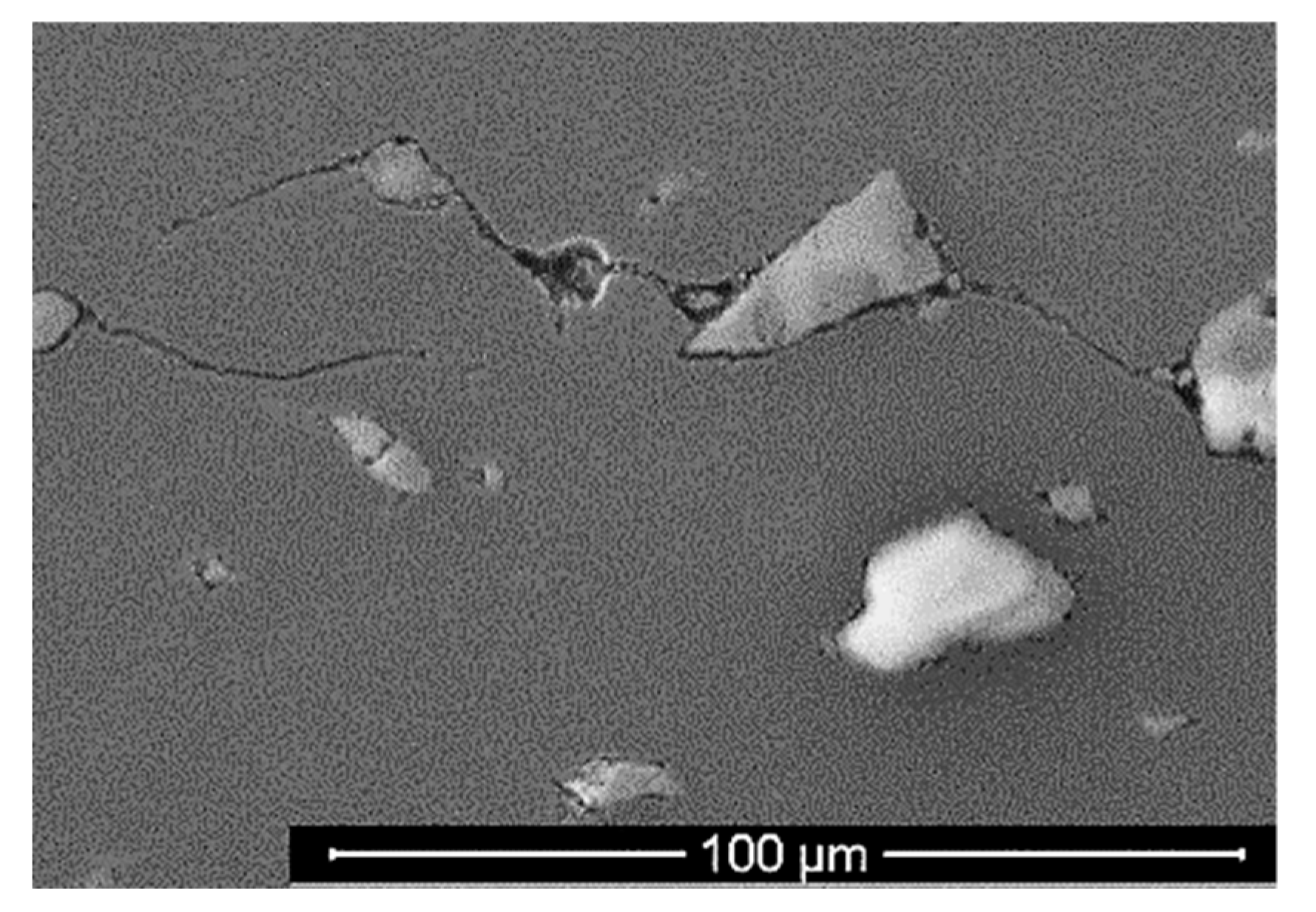
4.2. SEM Imaging
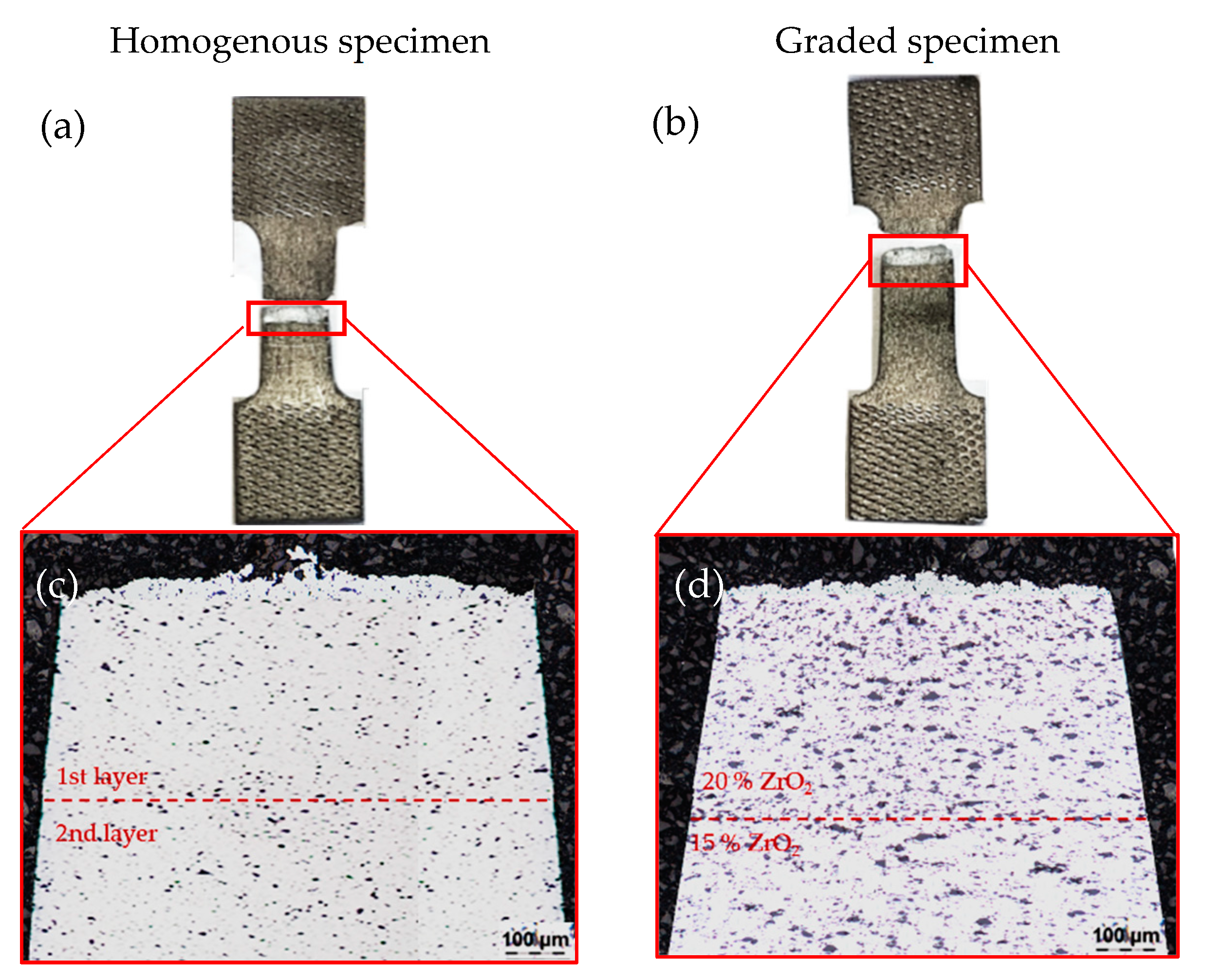
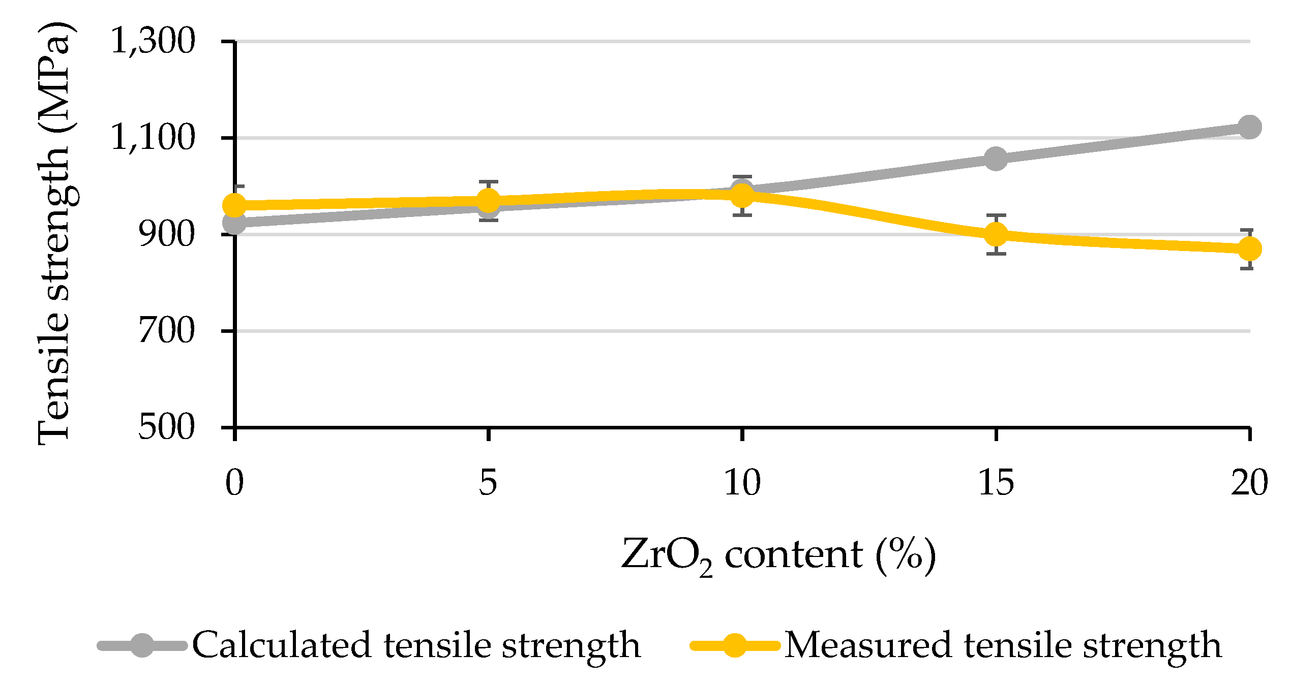
4.3. Tensile Tests
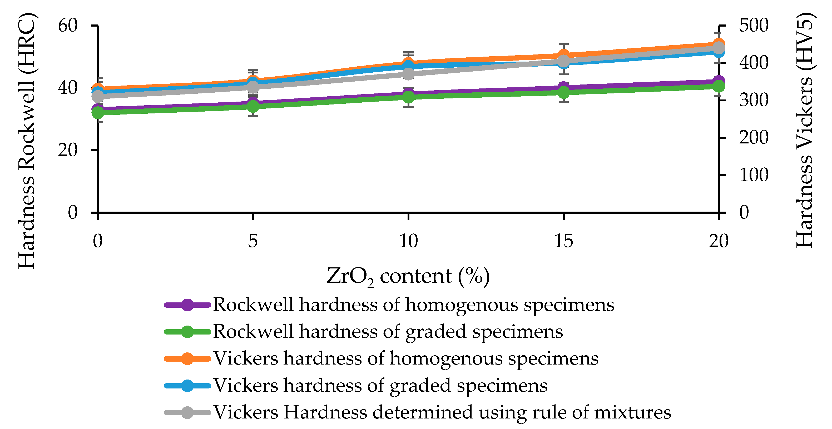
4.4. Hardness Tests
5. Conclusions
Author Contributions
Funding
Acknowledgments
Conflicts of Interest
References
- Liew, K.M.; Lei, Z.; Zhang, L.W. Mechanical analysis of functionally graded carbon nanotube reinforced composites: A review. Compos. Struct. 2015, 120, 90–97. [Google Scholar] [CrossRef]
- Pourmajidian, M.; Akhlaghi, F. Fabrication and Characterization of Functionally Graded Al/SiCp Composites Produced by Remelting and Sedimentation Process. J. Mater. Eng. Perform. 2014, 23, 444–450. [Google Scholar] [CrossRef]
- Birman, V.; Byrd, L.W. Modeling and Analysis of Functionally Graded Materials and Structures. Appl. Mech. Rev. 2007, 60, 195–216. [Google Scholar] [CrossRef]
- Raßbach, S. Grundlegende Untersuchungen zum Umformverhalten von Gradientenwerkstof-fen unter Anwendung von Druckformverfahren. PhD Thesis, TU Bergakademie Freiberg, Freiberg, Saxony, 2002. [Google Scholar]
- Elsner, P. Gradierte Werkstoffeigenschaften: Eine Herausforderung für die Fertigungs-technik. Futur 2005, 14, 16–18. [Google Scholar]
- Behrens, B.-A.; Vahed, N.; Brand, H. (Eds.) Pulvermetallurgische Herstellung gradierter Werkzeugwerkstoffe, 1st ed.; Leibniz Universität Hannover: Hannover, Germany, 2013. [Google Scholar]
- Kolaska, H. (Ed.) Fortschritte bei der Formgebung in Pulvermetallurgie und Keramik: Vorträge anlässlich des Symposiums am 28.29. November 1991 in Hagen; Verband Deutscher Ingenieure: Düsseldorf, Germany, 1991. [Google Scholar]
- Li, J.; Sun, W.; Ao, W.; Gu, K.; Xiao, P. Al2O3–FeCrAl composites and functionally graded materials fabricated by reactive hot pressing. Compos. Part A 2007, 28, 615–620. [Google Scholar] [CrossRef]
- He, Z.; Ma, J.; Tan, G. Fabrication and characteristics of alumina–iron functionally graded materials. J. Alloy. Compd. 2009, 486, 815–818. [Google Scholar] [CrossRef]
- Sahu, M.; Dargar, M.K.; Bartaria, V.N. The Effect of hot forging and heat treatment on tribologocal properties of Al alloy & nano composites. Int. J. Sci. Eng. Technol. 2013, 62, 649–661. [Google Scholar]
- Schiller, W. Neue Konzepte zum Kalibrieren von Sinterbauteilen. Master Thesis, Montanuniversität Leoben, Leoben, Austria, 2010. [Google Scholar]
- Zapf, G. Handbuch der Fertigungstechnik: Urformen; Carl Hanser Verlag: München, Germany, 1981. [Google Scholar]
- Vossen, K. Pulverschmieden von gerad- und schrägverzahnten Zylinderrädern. PhD Thesis, RWTH Aachen, Aachen, Germany, 1987. [Google Scholar]
- Kuhn, H.A.; Lynn, B. Powder forging. Powder Metall. 1990, 12, 13–19. [Google Scholar]
- Exner, H.E.; Danninger, H. Handbook of Inorganic Chemistry, Metallurgy of Iron: Powder Metallurgy of Steel, 10th ed.; Springer: Berlin/Heidelberg, Germany, 1992. [Google Scholar]
- Gillia, O.; Caillens, B. Fabrication of a material with composition gradient for metal/ceramic assembly. Powder Technol. 2011, 208, 355–366. [Google Scholar] [CrossRef]
- Chawla, N.; Shen, Y.-L. Mechanical Behavior of Particle Reinforced Metal Matrix Composites. Adv. Eng. Mater. 2001, 6, 357–370. [Google Scholar] [CrossRef]
- Kaczmar, J.; Pietrzak, K.; Włosiński, W. The production and application of metal matrix composite materials. J. Mater. Process. Technol. 2000, 106, 58–67. [Google Scholar] [CrossRef]
- Miracle, D. Metal matrix composites–From science to technological significance. Compos. Sci. Technol. 2005, 65, 2526–2540. [Google Scholar] [CrossRef]
- Biermann, H.; Aneziris, C.G.; Kolbe, A.; Martín, U.; Müller, A.; Schärfl, W.; Herrmann, M. Microstructure and compression strength of novel TRIP-steel/Mg-PSZ composites. Adv. Eng. Mater. 2010, 12, 1000–1006. [Google Scholar] [CrossRef]
- Glage, A.; Weigelt, C.; Räthel, J.; Biermann, H. Fatigue behaviour of hot pressed austenitic TWIP steel and TWIP steel/Mg-PSZ composite materials. Int. J. Fatigue 2014, 65, 9–17. [Google Scholar] [CrossRef]
- Ehinger, D.; Krüger, L.; Martin, U.; Weigelt, C.; Aneziris, C. Buckling and crush resistance of high-density TRIP-steel and TRIP-matrix composite honeycombs to out-of-plane compressive load. Int. J. Solids Struct. 2015, 66, 207–217. [Google Scholar] [CrossRef]
- Weigelt, C.; Jahn, E.; Berek, H.; Aneziris, C.G.; Eckner, R.; Krüger, L. Joining of Zirconia Reinforced Metal-Matrix Composites by a Ceramics-Derived Technology. Adv. Eng. Mater. 2015, 17, 1357–1364. [Google Scholar] [CrossRef]
- Zhou, Y.; Guo, Y.; Li, D. Effects of load mode on mechanical properties of ZrO2 (2Y)/TRIP steel composites. Trans. Nonferrous Met. Soc. China 2003, 13, 1086–1091. [Google Scholar]
- Guo, Y.; Zhou, Y.; Li, D. Microstructure and performance of 2Y-PSZ/TRIP steel composites. J. Mater. Sci. Technol. 2003, 19, 137–140. [Google Scholar]
- Weigelt, C.; Aneziris, C.; Ehinger, D.; Eckner, R.; Krüger, L.; Ullrich, C.; Rafaja, D. Effect of zirconia and aluminium titanate on the mechanical properties of transformation-induced plasticity-matrix composite materials. J. Compos. Mater. 2015, 49, 3567–3579. [Google Scholar] [CrossRef]
- Zackay, V.F.; Parker, E.R.; Fahr, D.; Busch, R. The enhancement of ductility in high-strength steels. Trans. Am. Soc. 1967, 60, 252–259. [Google Scholar]
- Tamura, I. Deformation-induced martensitic transformation and transformation-induced plasticity in steels. Met. Sci. 2013, 5, 245–253. [Google Scholar] [CrossRef]
- Kirschner, M. Beitrag zur Bewertung des Verdichtungsgrades mittels Visioplatsizität; Werkstoffwoche: Dresden, Germany, 2019. [Google Scholar]
- Kirschner, M.; Eckner, R.; Guk, S.; Krüger, L.; Kawalla, R.; Prahl, U. Deformation Behavior of Particle Reinforced TRIP Steel/MgPSZ Composite at Hot Working Temperatures. Steel Res. Int. 2019, 90, 1800334. [Google Scholar] [CrossRef]
- Kirschner, M.; Guk, S.; Kawalla, R.; Prahl, U. Further Development of Process Maps for TRIP Matrix Composites during Powder Forging. Mater. Sci. Forum 2019, 949, 15–23. [Google Scholar] [CrossRef]
- Biermann, H.; Aneziris, C.G. (Eds.) Austenitic TRIP/TWIP Steels and Steel-Zirconia Composites: Powder Forging of pre-sintered TRIP-Matrix Composites. (M. Kirschner, S. Guk, R. Kawalla, U. Prahl); Springer Series in Materials Science 298; Springer: Berlin/Heidelberg, Germany, 2020; Volume 1. [Google Scholar]
- Martin, S.; Berek, H.; Aneziris, C.G.; Martin, U.; Rafaja, D. Pitfalls of local and quantitative phase analysis in partially stabilized zirconia. J. Appl. Crystallogr. 2012, 45, 1136–1144. [Google Scholar] [CrossRef]
- Deutsches Institut für Normung. Bibl 1976, 10. [CrossRef]
- Meyer, R.J.; Pietsch, E. (Eds.) Eisen-Härteprüfverfahren: Beziehung zwischen Härte und Zugfestigkeit, Achte Völlig neu Bearbeitete Auflage. Fe. Eisen. Iron (System-Nr. 59), F-e/C/1; Springer: Berlin/Heidelberg, Germany, 1974. [Google Scholar]
- Pranke, K.; Guk, S. Material Flow in Mg-PSZ Particle Reinforced TRIP-Matrix-Composites due to Hot-Rolling. Key Eng. Mater. 2016, 684, 97–103. [Google Scholar] [CrossRef]
- Guk, S.; Pranke, K.; Müller, W. Flow Curve Modelling of an Mg-PSZ Reinforced TRIP-matrix-composite. ISIJ Int. 2014, 54, 2416–2420. [Google Scholar] [CrossRef]
- Berek, H.; Yanina, A.; Weigelt, C.; Aneziris, C.G. Determination of the Phase Distribution in Sintered TRIP-Matrix/Mg-PSZ Composites using EBSD. Steel Res. Int. 2011, 82, 1094–1100. [Google Scholar] [CrossRef]
- Pavlyuchkov, D.; Dilner, D.; Savinykh, G.; Fabrichnaya, O. Phase Equilibria in the ZrO 2 -MgO-MnO x System. J. Am. Ceram. Soc. 2016, 99, 3136–3145. [Google Scholar] [CrossRef]
- Martin, S.; Decker, S.; Krüger, L.; Martin, U.; Rafaja, D. Microstructure Changes in TRIP Steel/Mg-PSZ Composites Induced by Low Compressive Deformation. Adv. Eng. Mater. 2013, 15, 600–608. [Google Scholar] [CrossRef]
- Bokuchava, G.; Gorshkova, Y.; Papushkin, I.V.; Guk, S.V.; Kawalla, R. Investigation of Plastically Deformed TRIP-Composites by Neutron Diffraction and Small-Angle Neutron Scattering Methods. J. Surf. Investig. X-ray Synchrotron Neutron Tech. 2018, 12, 227–232. [Google Scholar] [CrossRef]
- Guk, S.; Milisova, D.; Pranke, K. Influence of Deformation Conditions on the Microstructure and Formability of Sintered Mg-PSZ Reinforced TRIP-Matrix-Composites. Key Eng. Mater. 2016, 684, 86–96. [Google Scholar] [CrossRef]
- Li, C.; Ellyin, F. Short crack growth behavior in a particulate-reinforced aluminum alloy composite. Met. Mater. Trans. A 1995, 26, 3177–3182. [Google Scholar] [CrossRef]
- Hochreiter, E.; Panzenböck, M.; Jeglitsch, F. Fatigue properties of particle-reinforced metal-matrix composites. Int. J. Fatigue 1993, 15, 493–499. [Google Scholar] [CrossRef]
- Seo, B.H.; Kim, J.; Park, J.B.; Jung, G.D. Crack propagation characteristics of particulate reinforced composites using digital image correlation. Mater. und Werkst. 2015, 46, 387–393. [Google Scholar] [CrossRef]
- Shang, J.K.; Ritchie, R. On the particle-size dependence of fatigue-crack propagation thresholds in SiC-particulate-reinforced aluminum-alloy composites: Role of crack closure and crack trapping. Acta Met. 1989, 37, 2267–2278. [Google Scholar] [CrossRef]
- Wang, Z.; Zhang, R.J. Microscopic characteristics of fatigue crack propagation in aluminum alloy based particulate reinforced metal matrix composites. Acta Met. et Mater. 1994, 42, 1433–1445. [Google Scholar] [CrossRef]
- Guk, S.; Müller, W.; Pranke, K.; Kawalla, R. Mechanical Behaviour Modelling of an Mg-Stabilized Zirconia Reinforced TRIP-Matrix-Composite under Cold Working Conditions. Mater. Sci. Appl. 2014, 5, 812–822. [Google Scholar] [CrossRef]
- Vahed, N. Einfluss des Materialflusses auf die Verdichtung beim Sinterschmieden; Umformtechnik: Verlag Meisenbach GmbH, Bamberg, Germany, 2014; pp. 2–11. [Google Scholar]


| TRIP Steel | Fe | C | Cr | Ni | Mn | Si | N | Al | S | Mo | Ti |
| (wt%) | bal. | 0.03 | 16.3 | 6.6 | 7.2 | 1.0 | 0.09 | 0.04 | <0.01 | <0.01 | <0.01 |
| Mg-PSZ | ZrO2 | HfO2 | MgO | SiO2 | Al2O3 | CaO | TiO2 | Y2O3 | |||
| (wt%) | bal. | 1.85 | 3.25 | 0.1 | 1.58 | 0.06 | 0.13 | 0.13 |
| ZrO2 Content (%) | Tensile Yield Strength (MPa) | Ultimate Tensile Strength (MPa) | Fracture Strain (%) |
|---|---|---|---|
| 0 | 304 | 959 | 39 |
| 5 | 393 | 951 | 36 |
| 10 | 469 | 948 | 35 |
| 15 | 518 | 875 | 26 |
| 20 | 577 | 858 | 16 |
| Graded | 442 | 894 | 28 |
© 2020 by the authors. Licensee MDPI, Basel, Switzerland. This article is an open access article distributed under the terms and conditions of the Creative Commons Attribution (CC BY) license (http://creativecommons.org/licenses/by/4.0/).
Share and Cite
Kirschner, M.; Martin, S.; Guk, S.; Prahl, U.; Kawalla, R. Forming Complex Graded and Homogeneous Components by Joining Simple Presintered Parts of TRIP-Matrix Composite through Powder Forging. Metals 2020, 10, 543. https://doi.org/10.3390/met10040543
Kirschner M, Martin S, Guk S, Prahl U, Kawalla R. Forming Complex Graded and Homogeneous Components by Joining Simple Presintered Parts of TRIP-Matrix Composite through Powder Forging. Metals. 2020; 10(4):543. https://doi.org/10.3390/met10040543
Chicago/Turabian StyleKirschner, Markus, Stefan Martin, Sergey Guk, Ulrich Prahl, and Rudolf Kawalla. 2020. "Forming Complex Graded and Homogeneous Components by Joining Simple Presintered Parts of TRIP-Matrix Composite through Powder Forging" Metals 10, no. 4: 543. https://doi.org/10.3390/met10040543
APA StyleKirschner, M., Martin, S., Guk, S., Prahl, U., & Kawalla, R. (2020). Forming Complex Graded and Homogeneous Components by Joining Simple Presintered Parts of TRIP-Matrix Composite through Powder Forging. Metals, 10(4), 543. https://doi.org/10.3390/met10040543