Production and Properties of Electron-Beam-Welded Joints on Ti-TiB Titanium Alloys

 ,
, 
Abstract
1. Introduction
2. Materials and Methods
3. Results and Discussion
3.1. Welding of Similar Joints Ti-TiB Alloy
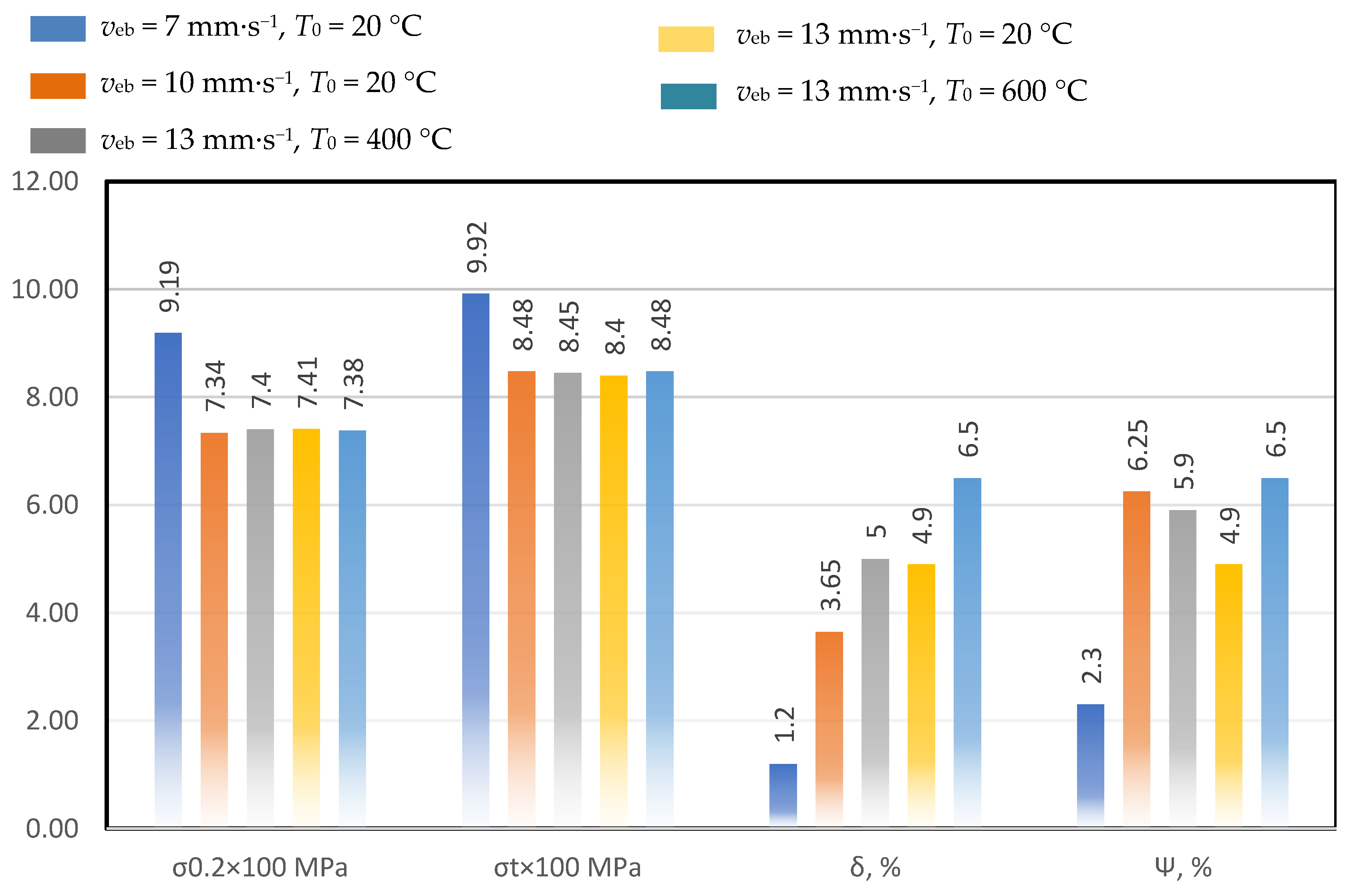
3.1.1. Influences of Welding Parameters on Microstructure and Mechanical Properties
- -
- Base material hardly influenced by welding process;
- -
- Weld metal which is formed from the melt;
- -
- Transient zone which is formed during the melt’s interaction with the base material.
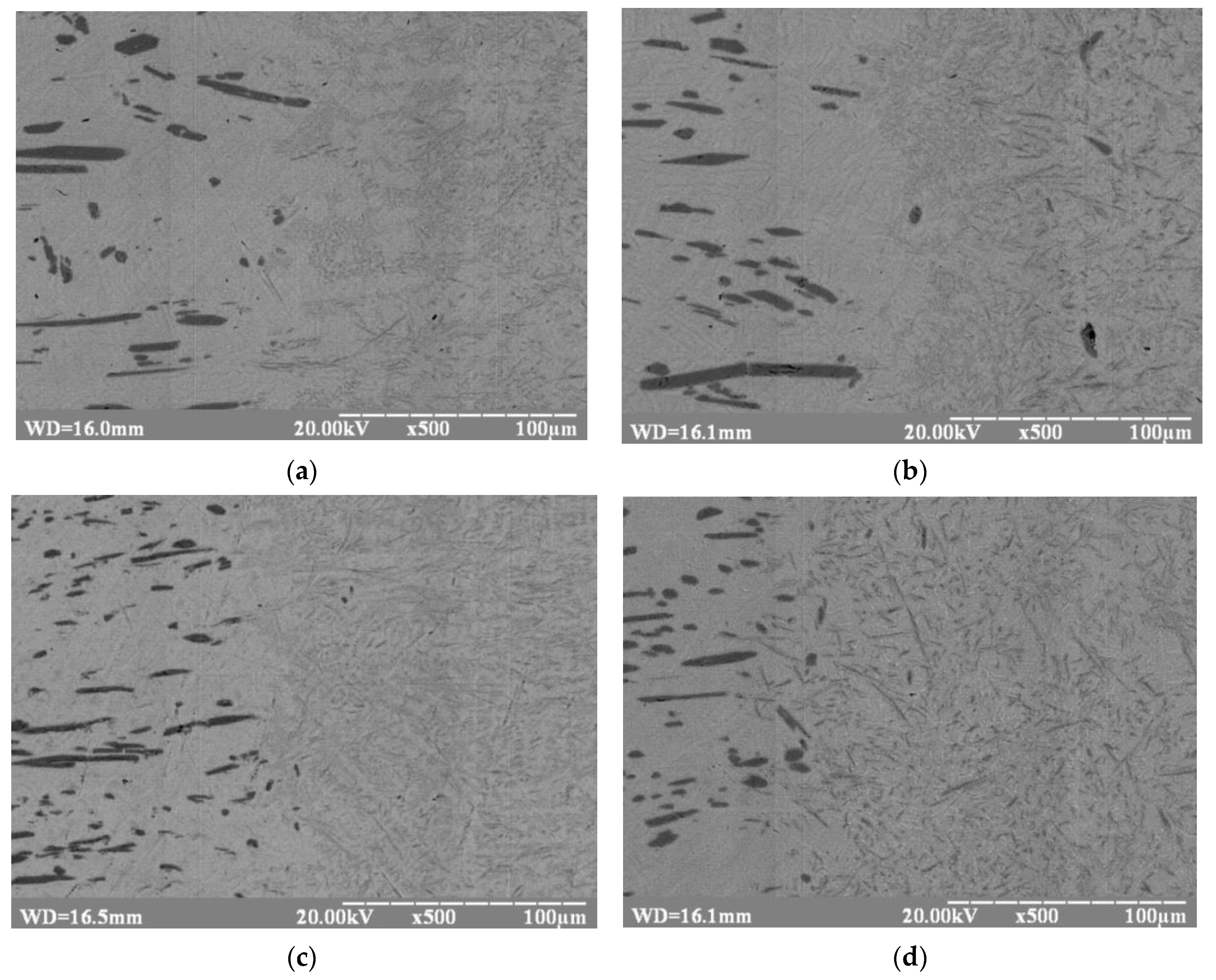
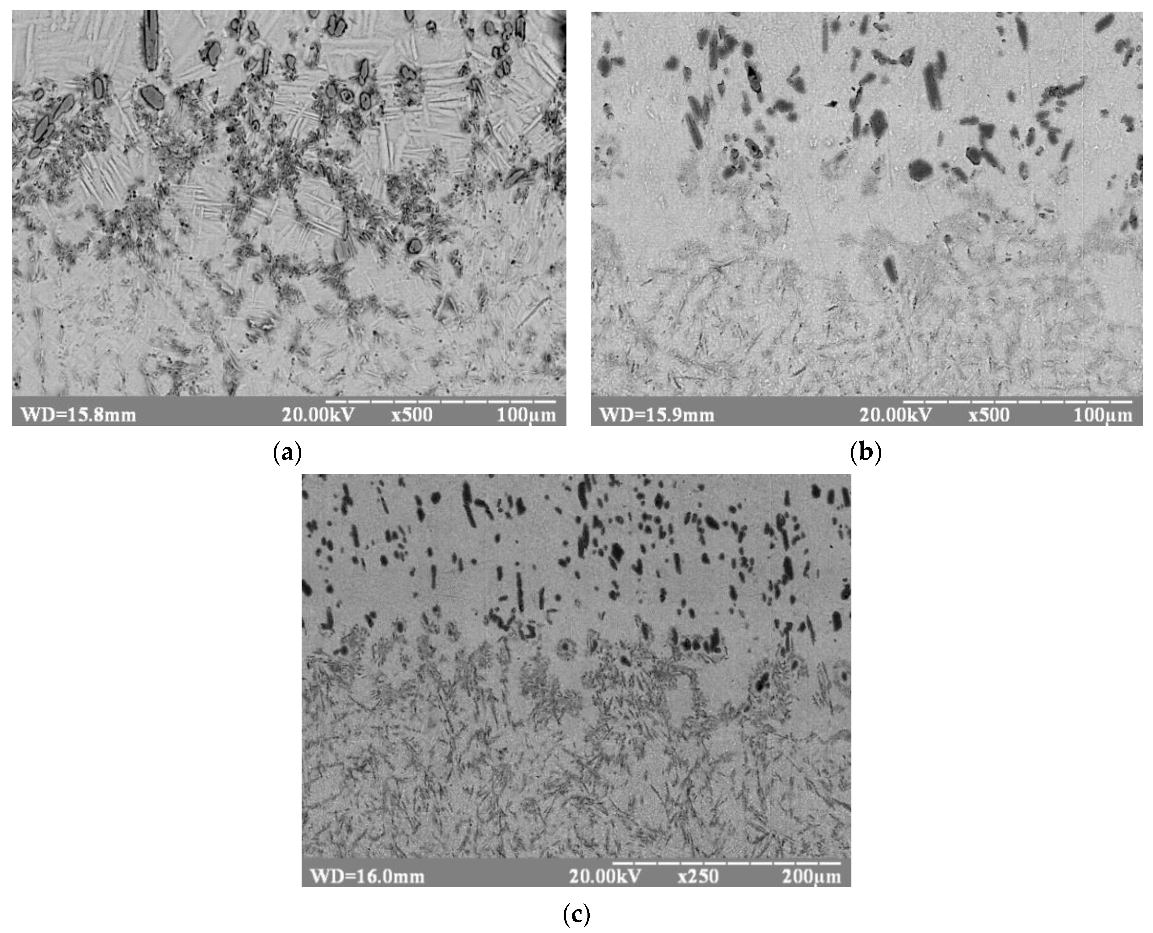
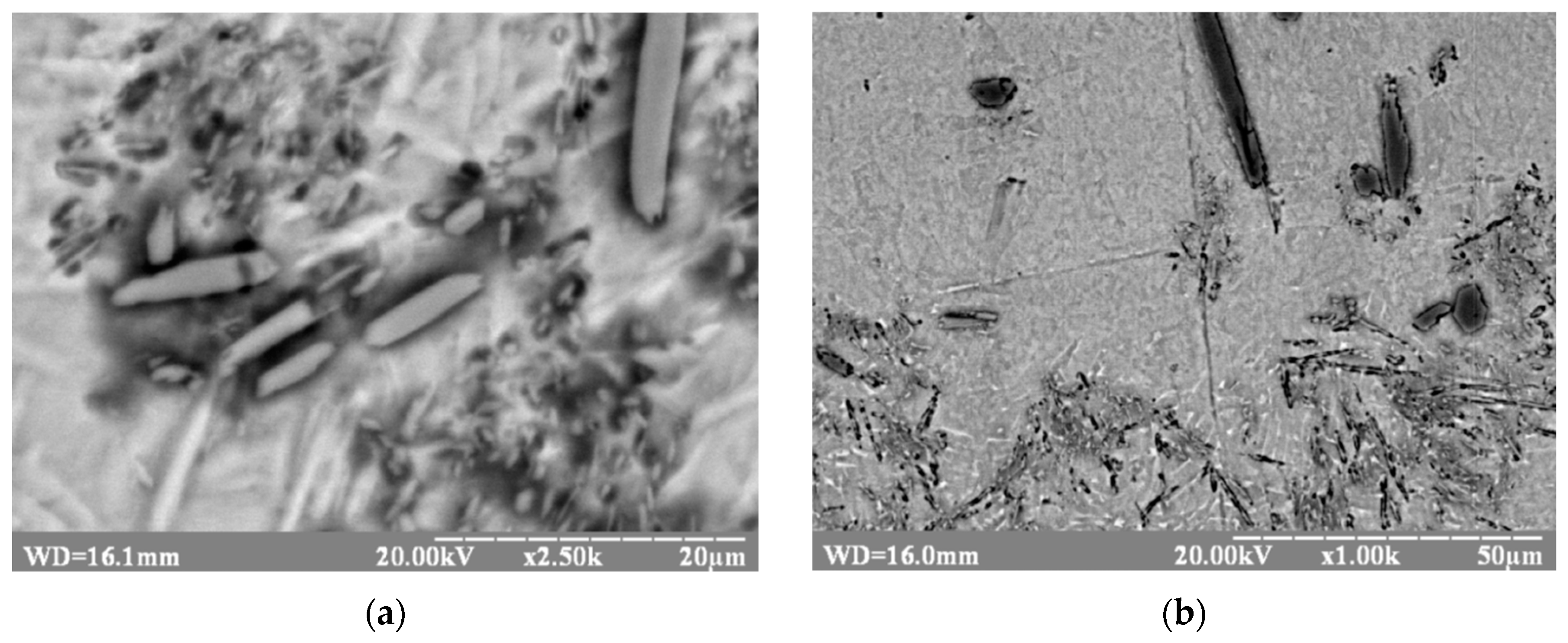
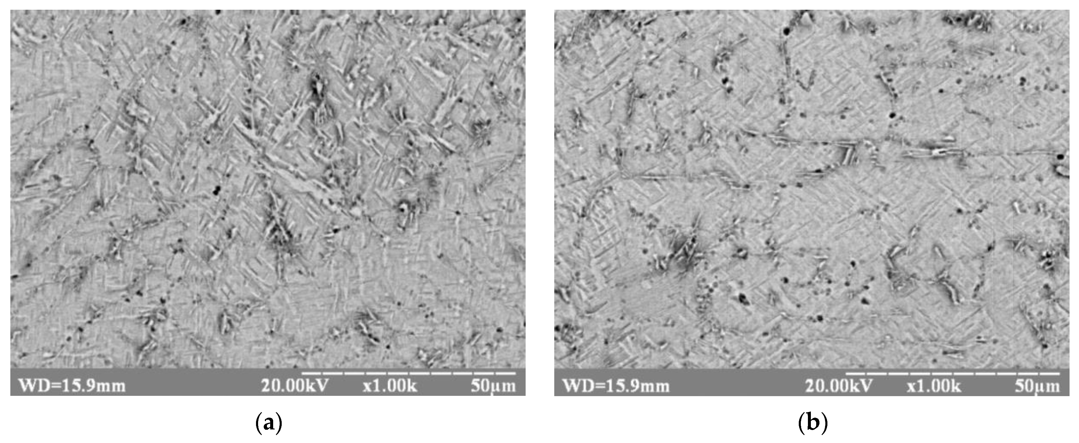
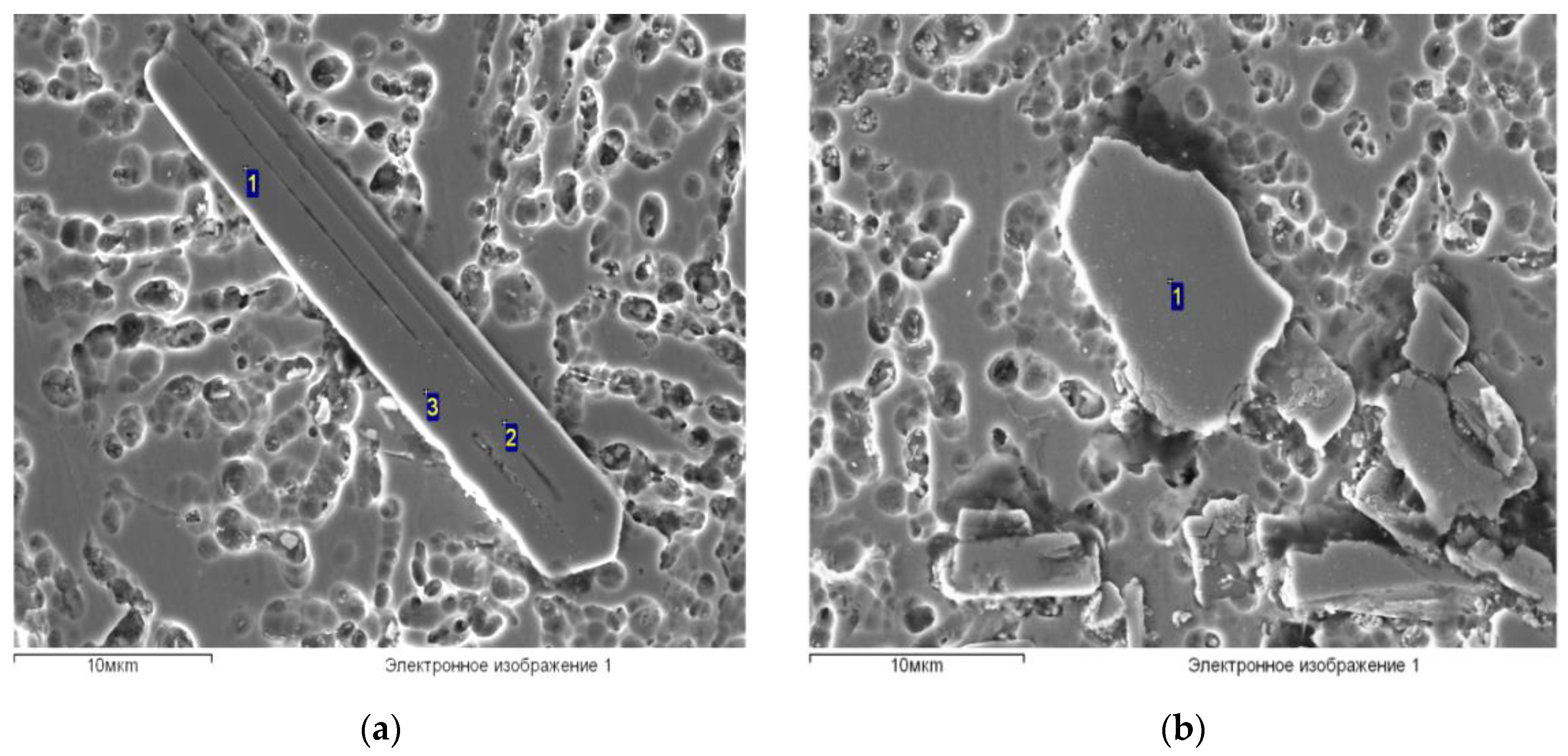
- Segregation of boron-containing fibers in areas with their increased content and formation of areas depleted with such phases (see Figure 6a).
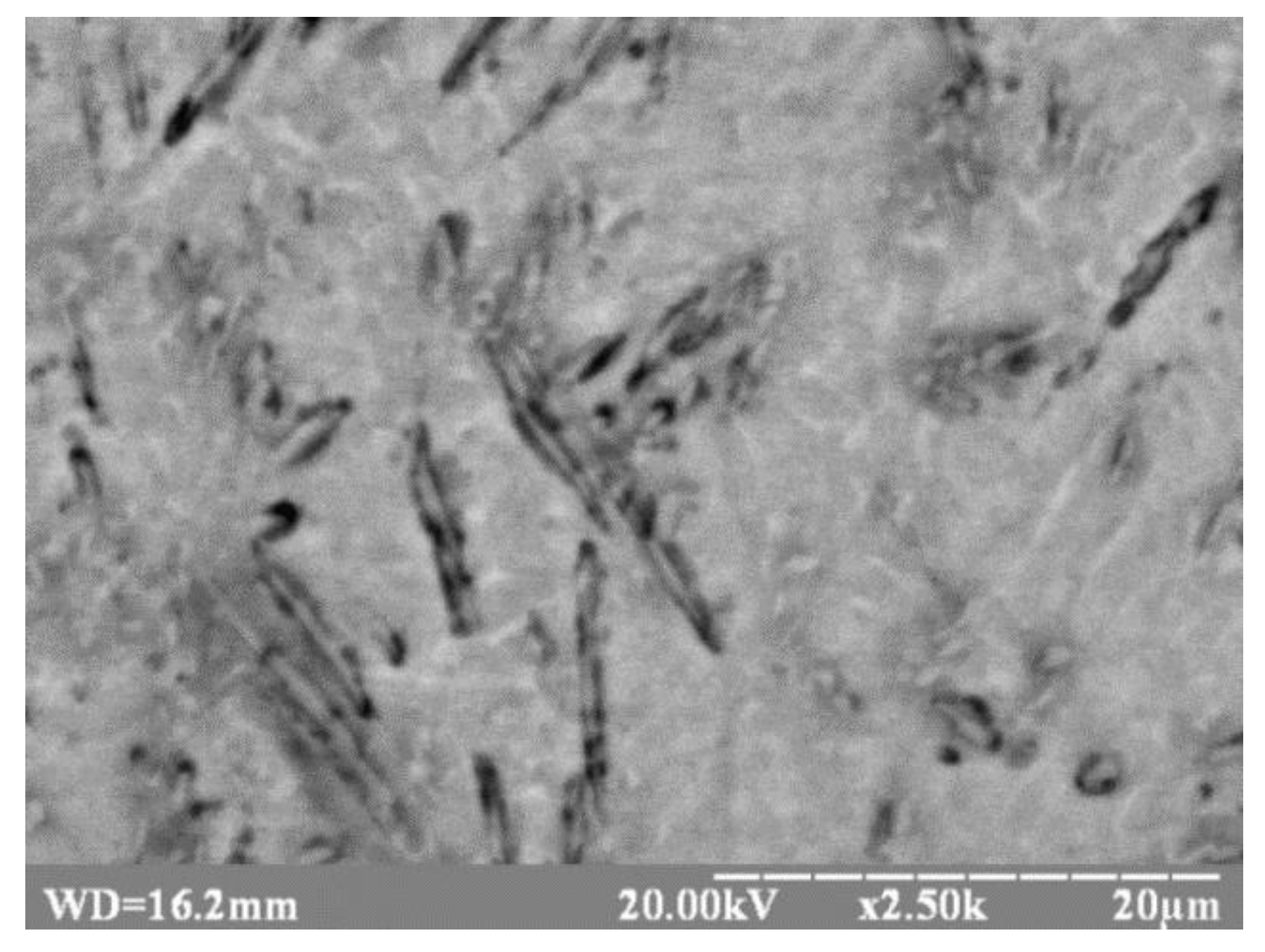
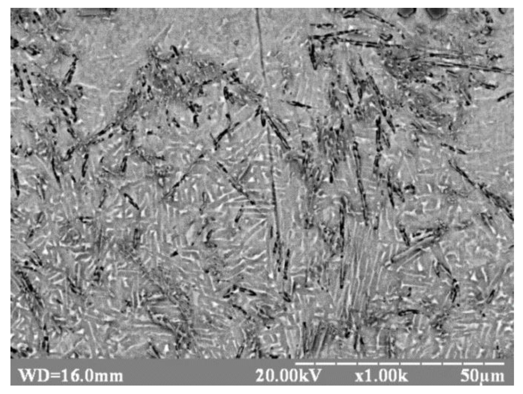
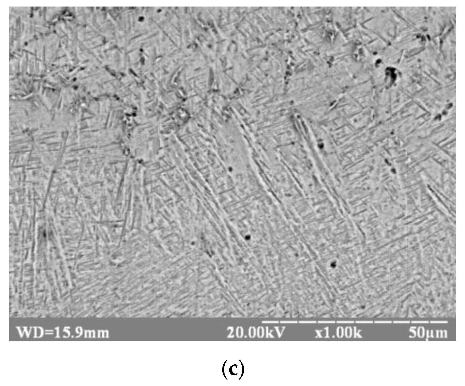
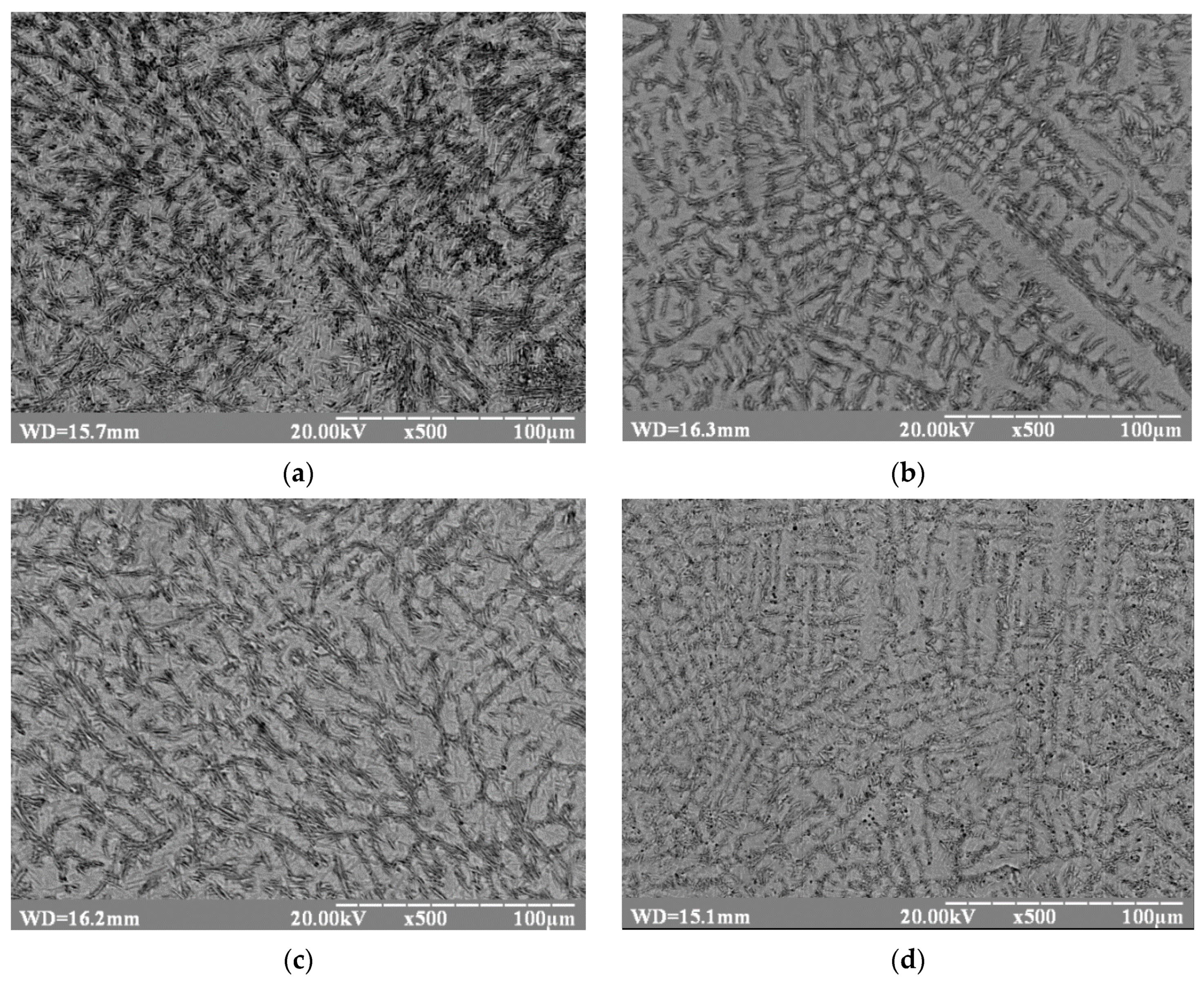
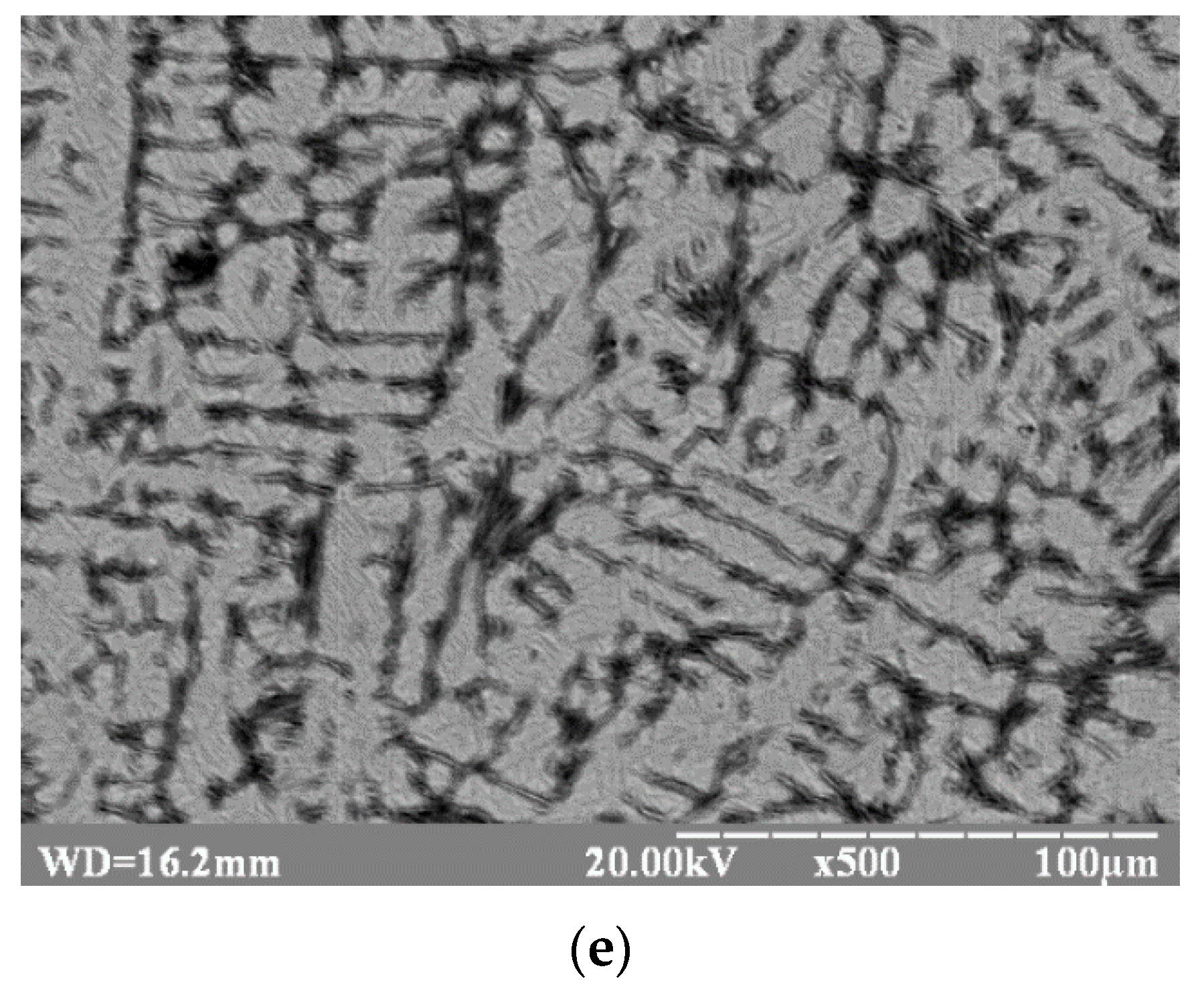
- Growth of boron-containing fibers both by length, and by thickness, upon increasing of residual temperature of joint subjected to welding both at the expense of the electron beam impact increase (see Figure 7a), and at the expense of preliminary heating (see Figure 7c). At that, the effect of preliminary heating is displayed to a considerably greater extent.
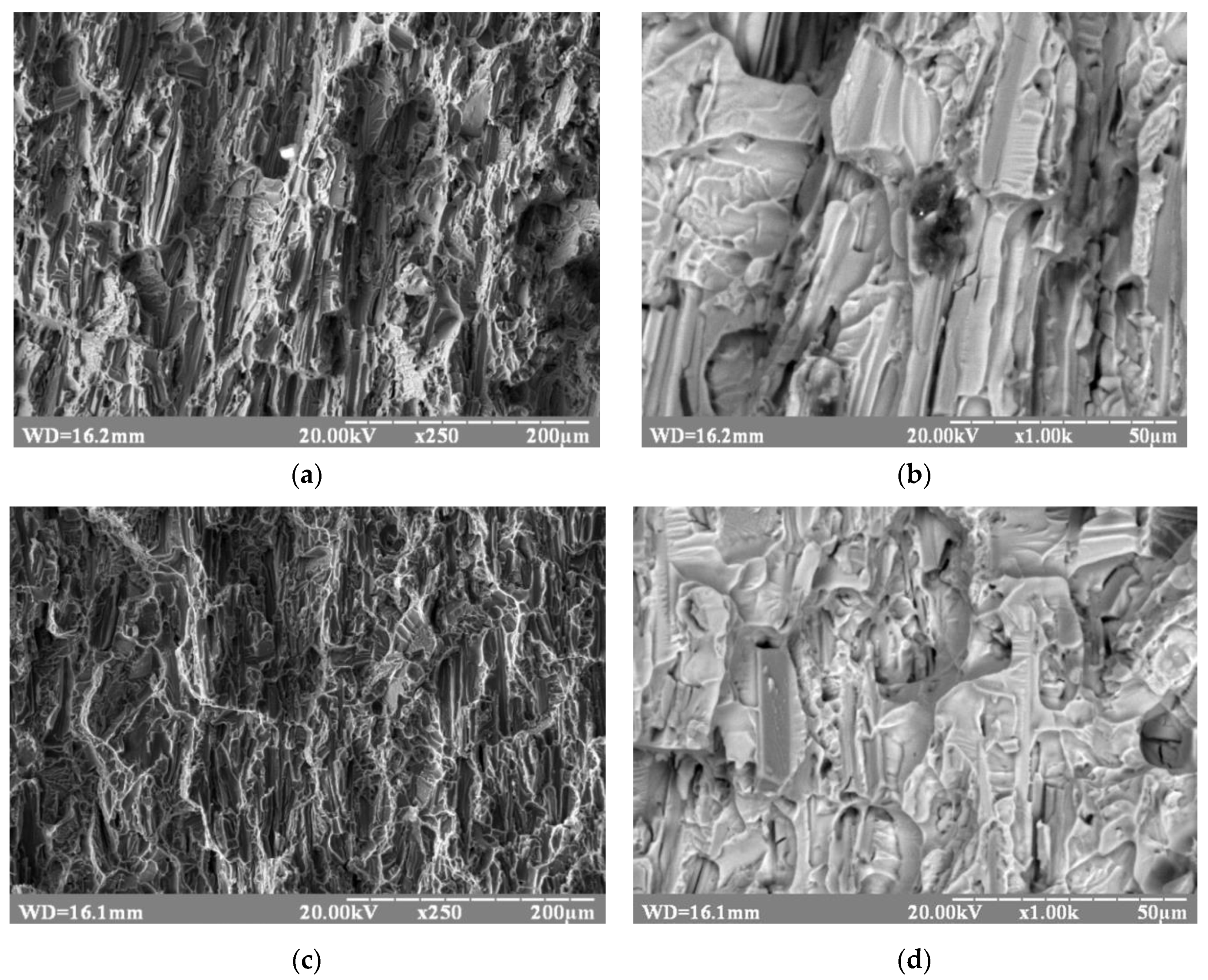
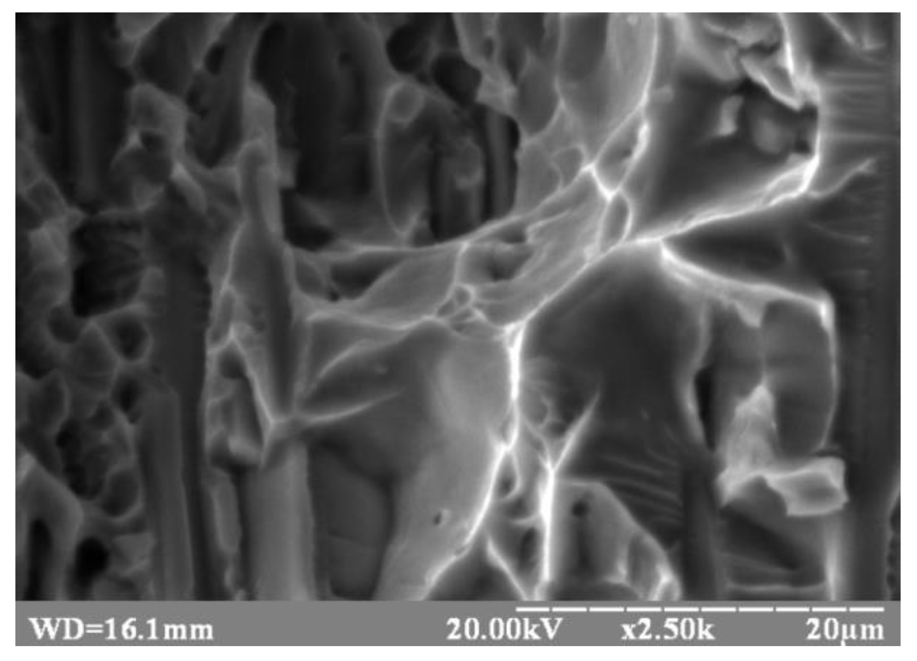
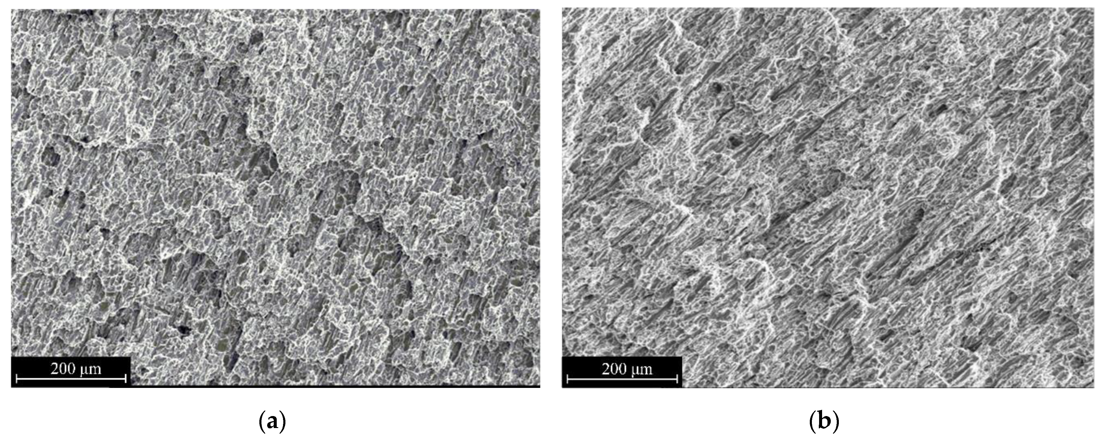
3.1.2. Fractographic Investigations
3.2. Welding of Dissimilar Joints between Ti-TiB and (α+β)Ti Alloy
Influences of Welding Parameters and Heat Treatment on Microstructure and Mechanical Properties
4. Conclusions
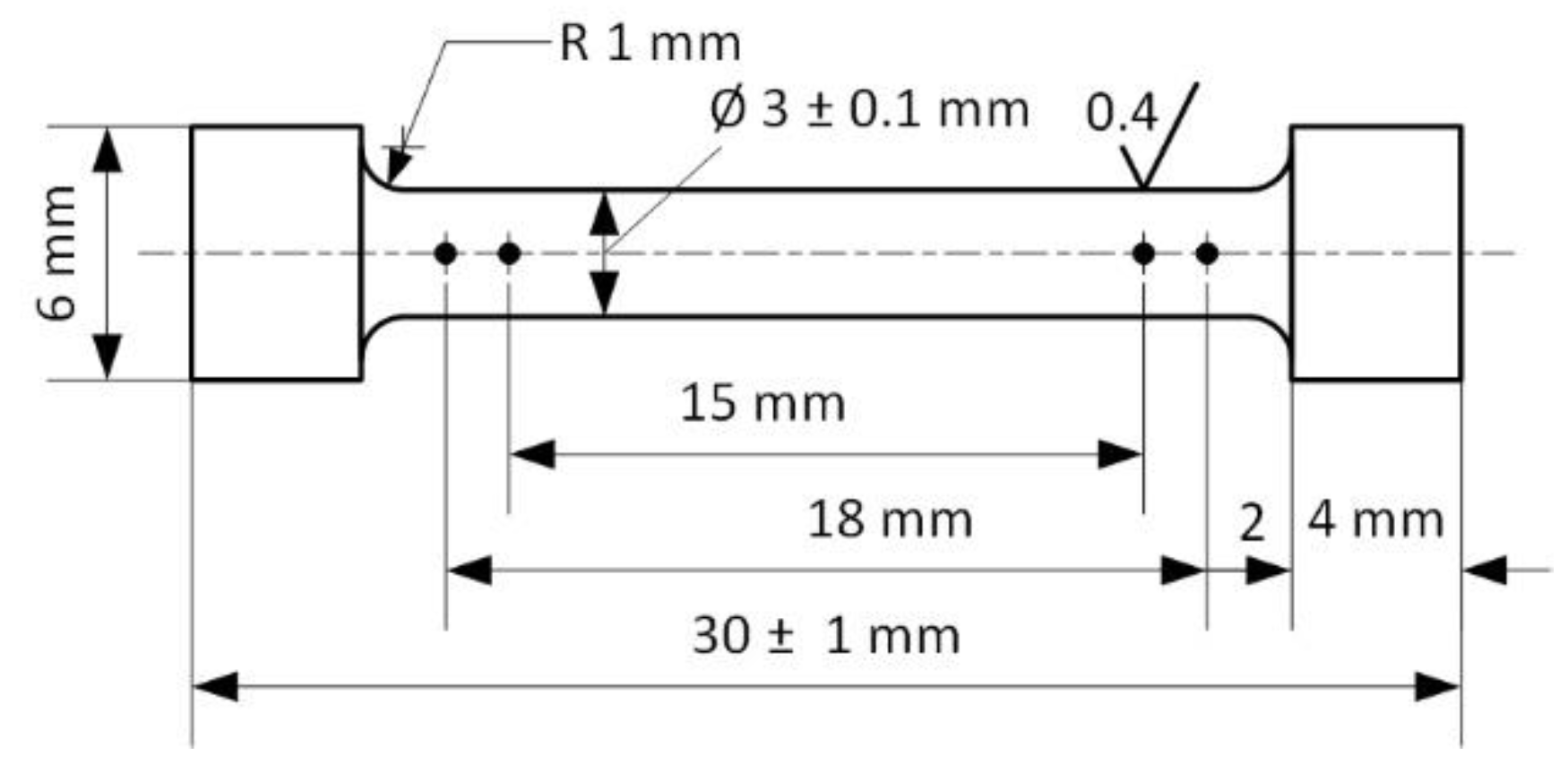
- The electron-beam welding with Uacc = 60 kV, Ieb = 90 mA, beam sweep elliptic (3 mm × 4 mm), transversal, under all values of veb in the range from 7 to 13 mm·s−1 ensures production of welded joints of Ti-TiB alloy samples, containing 5 mas. % of TiB2 in titanium base.
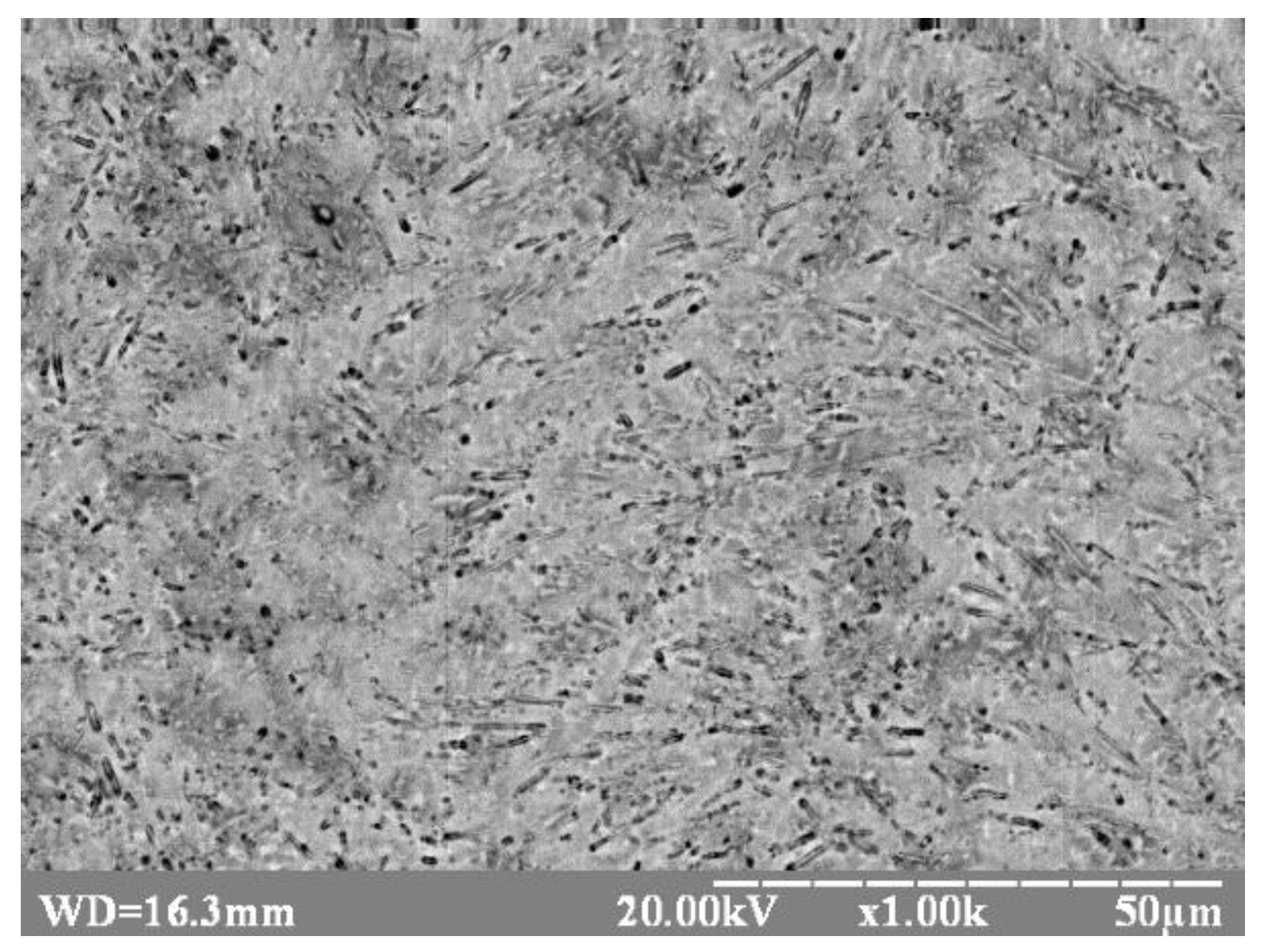
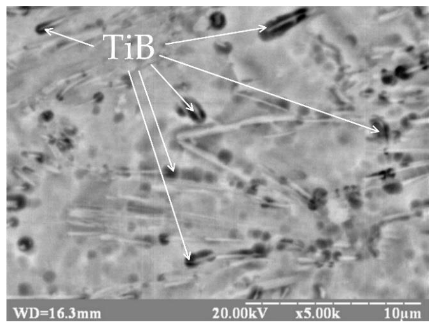
- During weld seam formation, the basic material is subjected to microstructural changes which result in decreasing of boron-containing fibers thickness from 3–8 µm to 0.1–0.9 µm. Their distinctive initial directionality is lost, and a considerable decrease in the thickness-to-length ratio of the fibers in the boron-containing phase was observed.
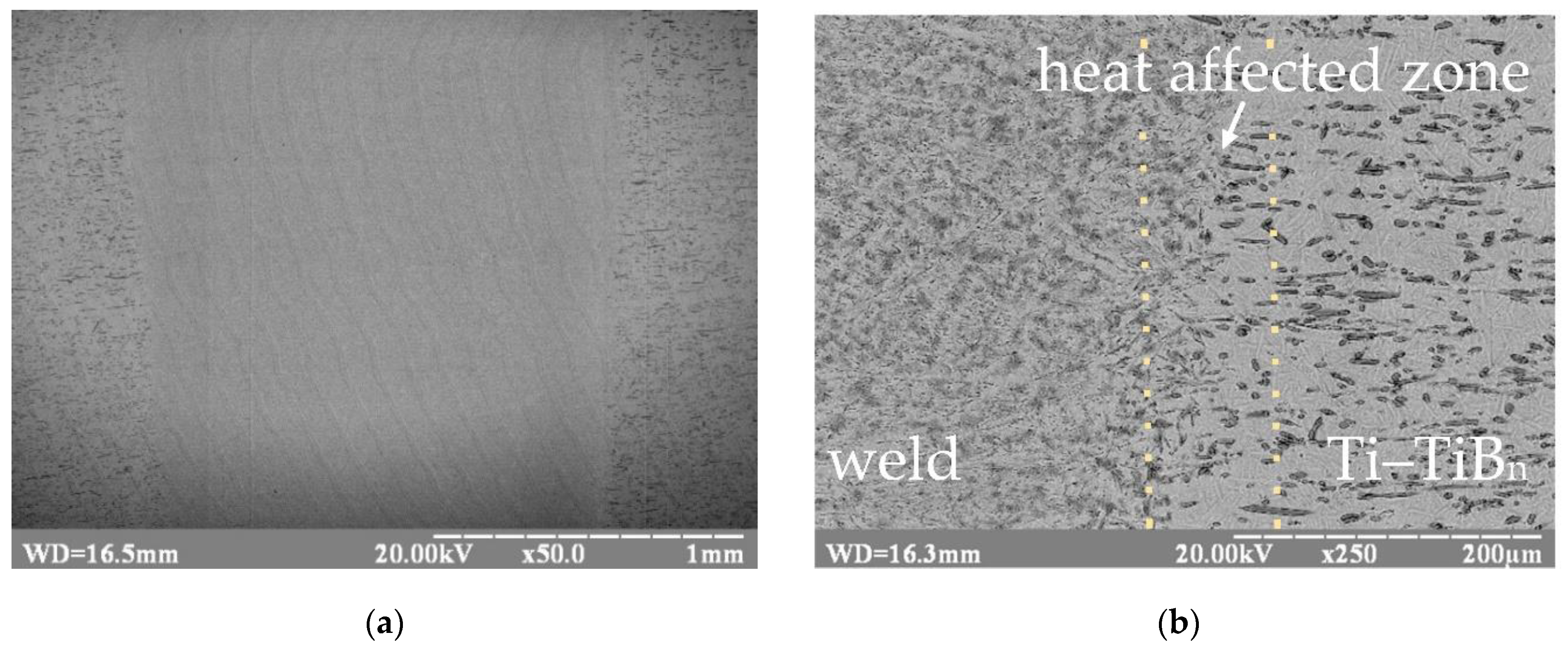
- The transient zone between the base metal and the welded seam material of Ti-TiB alloy has typical dimensions of 40–50 µm. In this zone both the boron-containing fibers of 3–8 µm thickness and 8–40 µm length, typical for an initial material, and thin long boron-containing fibers of 0.1–0.9 µm thickness and 3–15 µm length, typical for a welded seam, were observed.
- Preheating of welded samples to 400 °C results in a considerable rise of the homogeneity distribution degree of the boron-containing phase in the transient zone and an increase of fiber dimensions of this phase both by length and thickness, both in the transient zone and in the weld metal, compared to non-preheated specimens.
- Increase of electron beam movement velocity from 7 to 13 mm·s−1 results in an increase of the transient zone between base material and welded seam material and in a more uniform distribution of boron-containing fibers in titanium matrix.
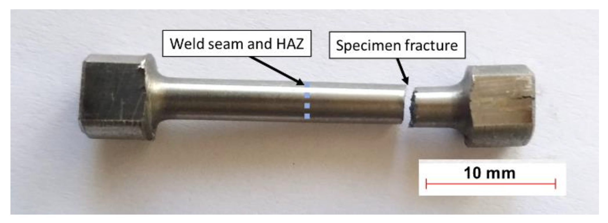
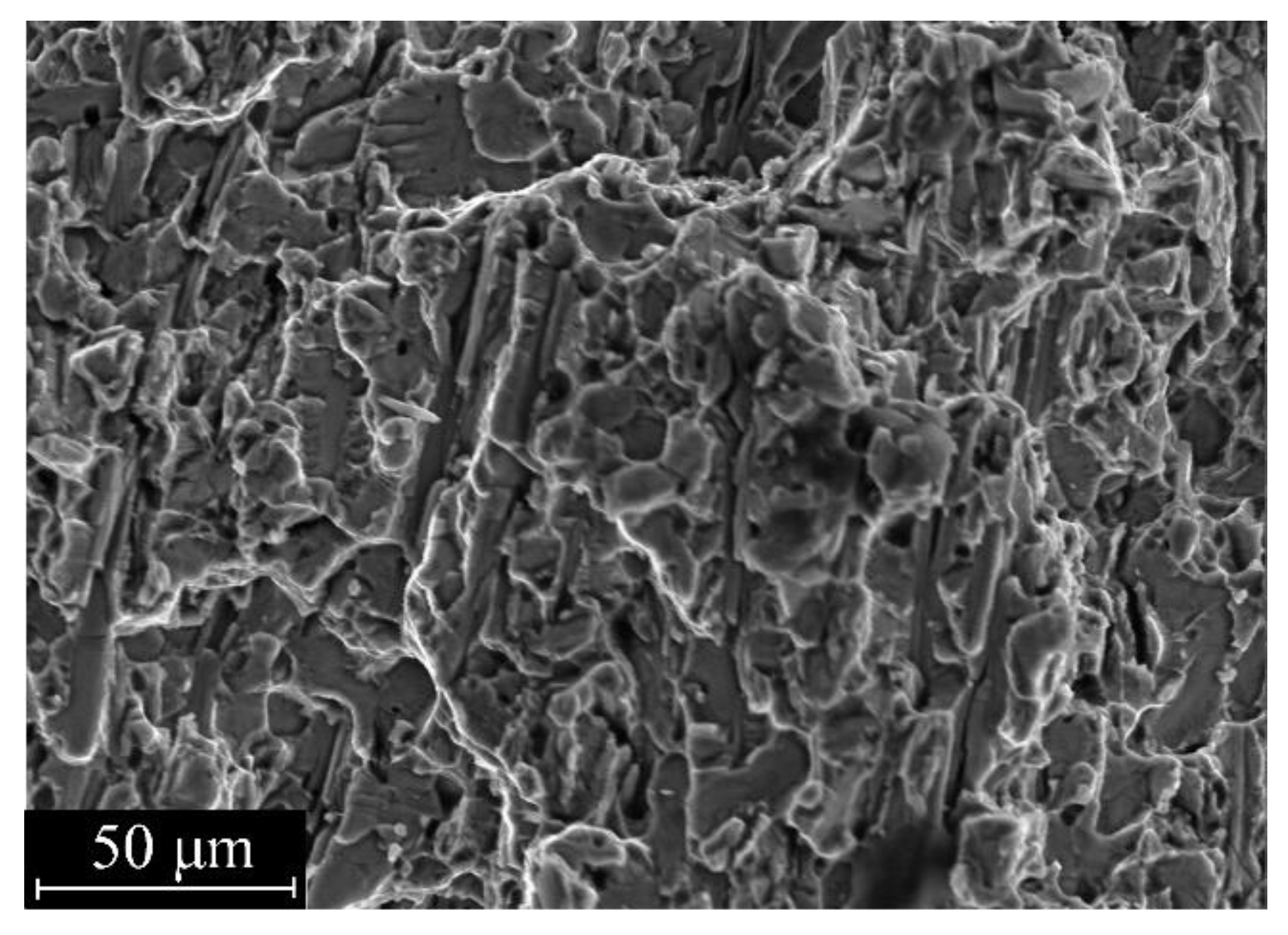
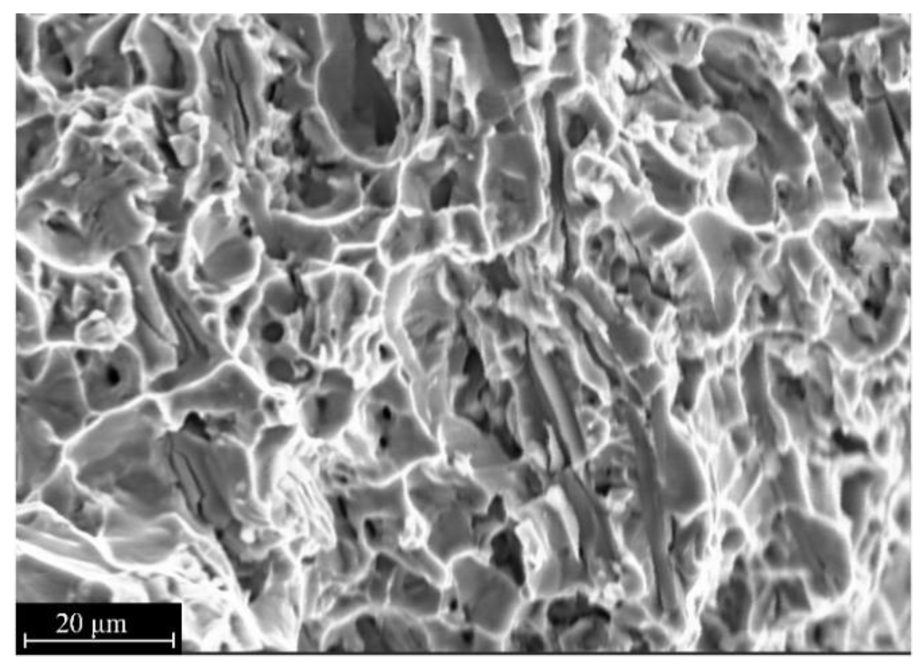
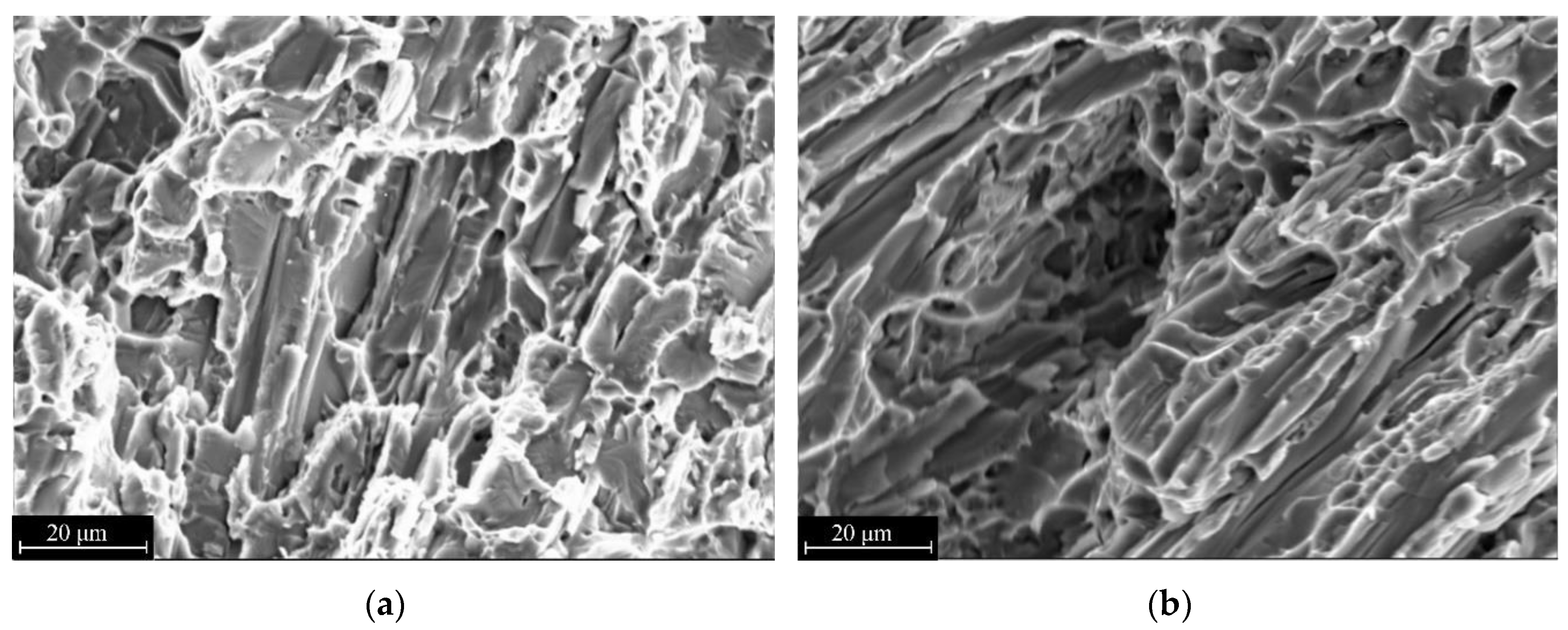
- Upon reaching the critical level of tensile stresses, the welded joints of Ti-TiB and T110 type alloys, produced by electron-beam welding under all values of veb in range from 7 to 13 mm·s−1 regardless of preheating, are fractured outside of the welded seam zone; the fracture surfaces show signs of mainly brittle fractures.
- Predominant transversal orientation of TiB-reinforcing fibers in Ti-TiB alloy leads to decrease of mechanical properties of dissimilar joints between Ti-TiB and T110. For such joints, the condition of Ti-TiB alloy is critical, as it is subjected to brittle fracturing. The thermal annealing of the welded joint at the temperature 750 °C (1 h) increases the plasticity of this alloy.
Author Contributions
Funding
Conflicts of Interest
References
- Gaisin, R.A.; Imayev, V.M.; Imayev, R.M.; Gaisina, É.R. Microstructure and mechanical properties of VT25U/TiB composite prepared in situ by casting and subjected to hot forging. Lett. Mater. 2017, 7, 186–196. [Google Scholar] [CrossRef][Green Version]
- Attar, H.; Bonisch, M.; Calin, M.; Zhang, L.-C.; Scudino, S.; Eckert, J. Selective laser melting of in situ titanium–titanium boride composites: Processing, microstructure and mechanical properties. Acta Mater. 2014, 76, 13–22. [Google Scholar] [CrossRef]
- Morsi, K.; Patel, V.V. Processing and properties of titanium–titanium boride (TiB) matrix composites—A review. J. Mater. Sci. 2007, 42, 2037–2047. [Google Scholar] [CrossRef]
- Rahoma, H.K.S.; Wang, X.P.; Kong, F.T.; Chen, Y.Y.; Han, J.C.; Derradji, M. Effect of (α+β) heat treatment on microstructure and mechanical properties of (TiB+TiC)/Ti-B20 matrix composite. Mater. Des. 2015, 87, 488–494. [Google Scholar] [CrossRef]
- García de Cortazar, M.; Agote, I.; Silveira, E.; Egizabal, P.; Coleto, J.; Petitcorps, Y.L. Titanium composite materials for transportation applications. JOM 2008, 60, 40–46. [Google Scholar] [CrossRef]
- Zhang, J.; Ke, W.; Ji, W.; Fan, Z.; Wang, W.; Fu, Z. Microstructure and properties of insitu titanium boride (TiB)/titanium (TI) composites. Mater. Sci. Eng. A 2015, 648, 158–163. [Google Scholar] [CrossRef]
- Kaczmarek, M.; Jurczyk, M.U.; Miklaszewski, A.; Paszel-Jaworska, A.; Romaniuk, A.; Lipińska, N.; Żurawski, J.; Urbaniak, P.; Jurczyk, K. In vitro biocompatibility of titanium after plasma surface alloying with boron. Mater. Sci. Eng. C 2016, 69, 1240–1247. [Google Scholar] [CrossRef] [PubMed]
- Vishniakov, L.R.; Grudina, T.V.; Kadyrov, V.K.; Karpinos, D.I.; Oleinik, V.I. Composition Materials: Reference Book; Naukova Dumka: Kiev, Ukraine, 1985; 589p. (In Russian) [Google Scholar]
- Gaisin, R.A.; Imayev, V.M.; Imayev, R.M. Microstructure and mechanical properties of Ti–TiB based short-fiber composite materials manufactured by casting and subjected to deformation processing. Russ. Phys. J. 2015, 58, 848–853. [Google Scholar] [CrossRef]
- Elliot, R. Eutectic Solidification Processing; Engl. transl.; Shvindlerman, L.S., Ed.; Metallurgy: Moscow, Russia, 1987; 352p. (In Russian) [Google Scholar]
- Paton, B.E.; Trigub, N.P.; Akhonin, S.V.; Zhuk, G.V. Titan Electron-Beam Melting; Naukova Dumka: Kiev, Ukraine, 2006; 248p, ISBN 966-00-0665-9. (In Russian) [Google Scholar]
- Grigorenko, G.M.; Akhonin, S.V.; Loboda, P.I.; Grigorenko, S.G.; Severin, A.Y.; Berezos, V.A.; Bogomol, Y.I. Structure and properties of titanium alloy, alloyed with boron, produced by the method of electron beam remelting. Electrometall. Today 2016, 1, 21–25. (In Russian) [Google Scholar] [CrossRef]
- Loboda, P.I. Directionally Crystallized Borides; Praimdruk: Kyiv, Ukraine, 2012; 395p. (In Ukrainian) [Google Scholar]
- Gurevich, S.M.; Zamkov, V.N.; Kompan, Y.Y.; Kushnirenko, N.A.; Kharchenko, G.K.; Blaschuk, V.E.; Volkov, V.B.; Zagrebenyuk, S.D.; Prilutsky, V.P.; Sabokar, V.K. Metallurgy and Technology of Welding of Titan and It Alloys; Zamkov, V.N., Ed.; Naukova Dumka: Kiev, Ukraine, 1986; 240p. (In Russian) [Google Scholar]
- Grigorenko, G.M.; Zadorozhnuk, O.M. Structure, mechanical properties and weldability of pseudo-α and (α+β)-Ti alloys strengthened by silicides. Electrometall. Today 2016, 2, 51–56. (In Russian) [Google Scholar] [CrossRef]
- Grabin, V.F. Fundamentals of Metal Science and Thermal Treatment of Welded Joints from Titanium Alloys; Naukova Dumka: Kiev, Ukraine, 1975; 262p. (In Russian) [Google Scholar]
- Shelyagin, V.D.; Khaskin, V.Y.; Akhonin, S.V.; Belous, V.Y.; Petrichenko, I.K.; Siora, A.V.; Palagesha, A.N.; Selin, R.V. Peculiarities of laser-arc welding of titanium alloys. Autom. Weld. 2012, 12, 36–40. (In Russian) [Google Scholar]
- Nazarenko, O.K.; Kajdalov, A.A.; Kovbasenko, S.N.; Bondarev, A.A.; Shevelev, A.A.; Chvertko, A.I.; Zubchenko, J.V.; Lankin, J.N.; Sheljagin, V.D. Electron-Beam Welding; Paton, B.E., Ed.; Naukova Dumka: Kiev, Ukraine, 1987; 255p. (In Russian) [Google Scholar]
- Akhonin, S.V.; Belous, V.Y.; Antonyuk, S.L.; Petrichenko, I.K.; Selin, R.V. Properties of high-strength titanium alloy T110 joints made by fusion welding. Autom. Weld. 2014, 1, 54–57. (In Russian) [Google Scholar]
- State Diagrams of Binary Metal Systems; Ljakishev, N.P., Ed.; Mashinostroenie: Moscow, Russia, 1996; Volume 1, 992p, ISBN 5-217-02688-X. (In Russian) [Google Scholar]
- Palty, A.E.; Margolin, H.; Nielsen, J.P. Titanium-Nitrogen and Titanium-Boron systems. Trans. ASM 1954, 46, 312. [Google Scholar]
- Khorev, A.I. Fundamental and applied works on titanium alloys and prospective lines of their development. Technol. Mach. Build. 2014, 11, 5–10. (In Russian) [Google Scholar]
- Bychkov, A.S.; Moliar, A.G. Operational load-carrying ability of constructional elements of domestic aircraft of transport category from titanium alloys. Open Inf. Comput. Integr. Technol. 2016, 71, 18–25. (In Russian) [Google Scholar]


| Material | Yield Strength σ0.2, MPa | Tensile Strength σt, MPa | Elongation δ, % | Reduction of Area Ψ, % | Vickers Hardness HV, MPa | References |
|---|---|---|---|---|---|---|
| Technical titanium | 350–500 | 450–550 | 25 | 55 | 1400–2000 | [12] |
| BT1-0 | - | 295–440 | 24–25 | 42–55 | - | GOST 26492-85 |
| Ti-TiB | 631 | 882 | 13 | 16 | 3500–3700 | [12] |
| No. of Sample Series | Electron Beam Movement Velocity, veb, mm·s−1 | Initial Temperature of Welded Materials, T0, °C | Logged Phases | Crystal Lattice Distortion, Δ, % | Average Size of Crystalline Blocks, ∏, 10−10 m | Mechanical Characteristics | Material Metallographic Structure in Welded Seam Area | |||
|---|---|---|---|---|---|---|---|---|---|---|
| Yield Strength σ0.2 MPa | Tensile Strength σt Mpa | Elongation δ % | Reduction of Area Ψ % | |||||||
| 1 | 7 | 20 | α Ti TiB | α Ti-0.1 TiB-0.209 | α Ti-150 TiB-56.36 | 957.2 | 1040 | 2.0 | 6.6 |  |
| 2 | 10 | 20 | α Ti-0 TiB-0.23 | α Ti-142 TiB-195.1 | - | 1023.1 | - | - |  | |
| 3 | 13 | 400 | α Ti-0 TiB-0.004 | α Ti-141 TiB-84.03 | - | 950.2 | - | - |  | |
| 4 | 13 | 20 | α Ti-0.2 TiB-0.41 | α Ti-140 TiB-86.65 | - | 950 | - | - |  | |
| No. of Sample Series | Heat Affected Zone (See Figure 6). Area, Retaining the Structural Peculiarities Both Base Material, and Weld Metal | Weld Metal (See Figure 7) | Base Material |
|---|---|---|---|
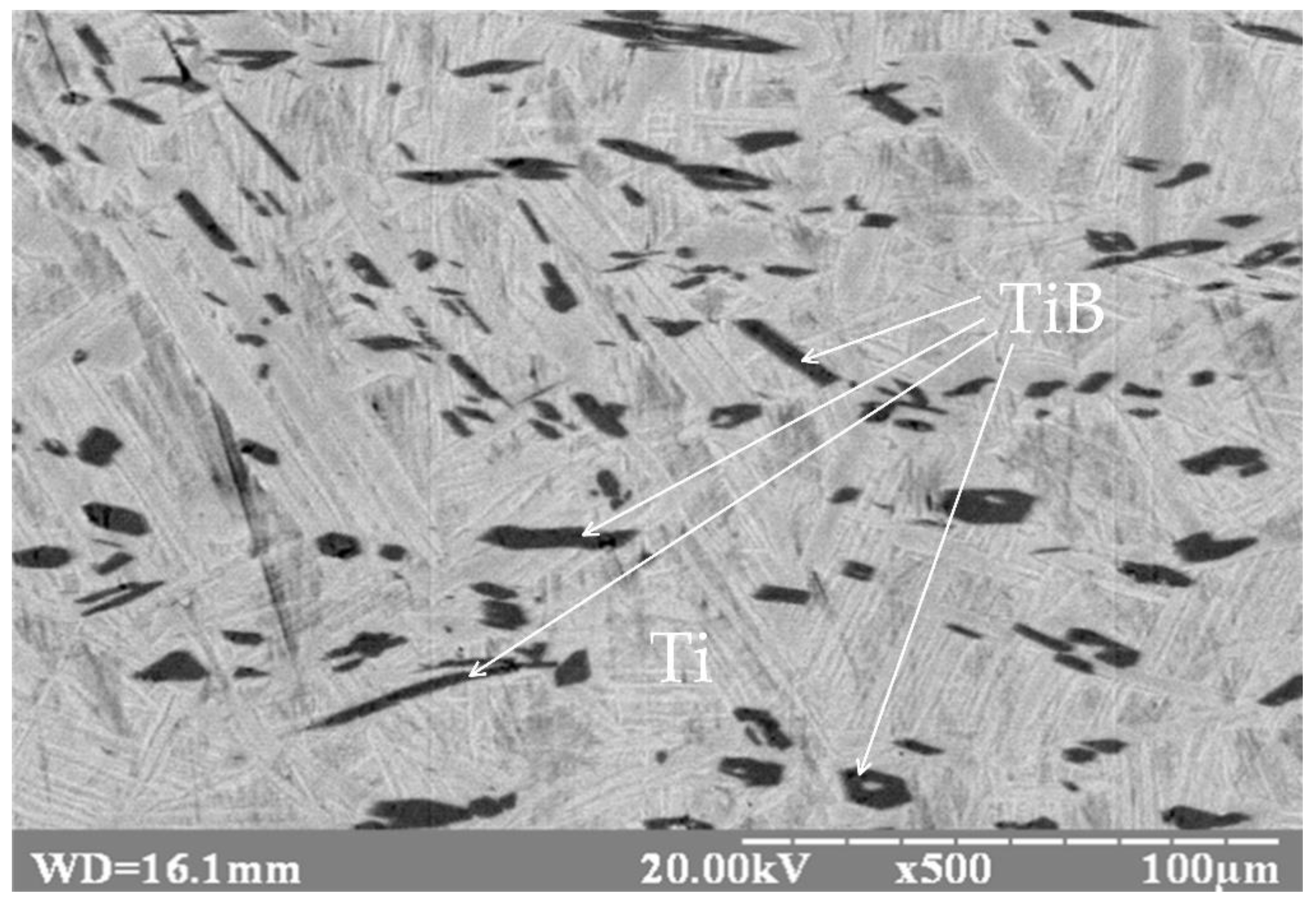
| 1 | Zone width is 50 µm on average. In the material are areas without fibrous inclusions, and areas engaging both initial large TiB fibers, and thin micron and submicron fibers. | TiB fibers have not predominant orientation (see Figure 6a). Fibers length is from 2 to 8 µm. TiB fibers thickness is correlated with their length in proportion from 1:4 to 1:8 on average. Average distance between fibers in Ti matrix is 1.5 µm. | It is typical the presence of large elongated grains of titanium boride, for which is typical the decrease of peak intensity of titanium characteristic X-ray emission by 1.2–1.3 times in comparison with the main titanium matrix. Fibers are distributed uniformly by whole volume (their thickness is 2–7 µm (see Figure 2)), fibers with length from 8 to 70 µm are observed. TiB fibers thickness is correlated with their length in proportion 1:3 on average, at that, this proportion for various inclusions is vary from 2:3 to 1:15. Orientation of reinforcing fibers is initial. |
| 2 | Zone width is 40 µm on average. In the material are areas without fibrous inclusions, and areas engaging both initial large TiB fibers, and thin micron and submicron fibers. | TiB fibers have not predominant orientation (see Figure 6b). Fibers length is from 1 to 4 µm. TiB fibers thickness is correlated with their length in proportion 1:5 on average, at that, this proportion for various inclusions is vary from 1:4 to 1:6. Average distance between fibers in Ti matrix is 0.8 µm. | |
| 3 | Zone width is 32 µm on average. Feature of structure in such transient zone in comparison with samples Nos. 1, 2 and 4 is more high degree of homogeneity which is approaching to the characteristics of welded seam material. | TiB fibers have not predominant orientation (see Figure 6c). Fibers length is from 5 to 20 µm. TiB fibers thickness is correlated with their length in proportion 1:9 on average, at that, this proportion for various inclusions is vary from 1:4 to 1:11. Average distance between fibers in Ti matrix is 4 µm. | |
| 4 | Zone width is 28 µm on average. In the material are areas without fibrous inclusions, and areas engaging both initial large TiB fibers, and thin micron and submicron fibers. | TiB fibers have not predominant orientation (see Figure 6d). Fibers length is from 2 to 6 µm. TiB fibers thickness is correlated with their length in proportion 1:10 on average, at that, this proportion for various inclusions is vary from 1:6 to 1:10. Average distance between fibers in Ti matrix is 0.8 µm. |
| No. of Sample Series | Kind of Welding Joint | Thermal Treatment | Mechanical Characteristics | Structure of Material in Weld Metal | Notes | |||
|---|---|---|---|---|---|---|---|---|
| Yield Strength σ0.2 MPa | Tensile Strength σt MPa | Elongation δ % | Reduction of Area Ψ % | |||||
| 5 | (Ti-TiB)–T110 | Without annealing | 918.9 | 991.5 | 1.2 | 2.3 | Reinforcing fibers along the load axis | Fracture by T110 alloy |
| 6 | Without annealing | - | 931.3 | - | - | Reinforcing fibers across the load axis | Fracture by (Ti-TiB) alloy | |
| 7 | Annealing 750 °C 1 h (air) | 928.7 | 970.5 | 2.0 | 5.9 | Reinforcing fibers are across | Fracture by (Ti-TiB) alloy | |
| 8 | Annealing 850 °C 1 h (vacuum) | - | 975.7 | - | - | Reinforcing fibers are across | Fracture by (Ti-TiB) alloy | |
© 2020 by the authors. Licensee MDPI, Basel, Switzerland. This article is an open access article distributed under the terms and conditions of the Creative Commons Attribution (CC BY) license (http://creativecommons.org/licenses/by/4.0/).
Share and Cite
Loboda, P.; Zvorykin, C.; Zvorykin, V.; Vrzhyzhevskyi, E.; Taranova, T.; Kostin, V. Production and Properties of Electron-Beam-Welded Joints on Ti-TiB Titanium Alloys. Metals 2020, 10, 522. https://doi.org/10.3390/met10040522
Loboda P, Zvorykin C, Zvorykin V, Vrzhyzhevskyi E, Taranova T, Kostin V. Production and Properties of Electron-Beam-Welded Joints on Ti-TiB Titanium Alloys. Metals. 2020; 10(4):522. https://doi.org/10.3390/met10040522
Chicago/Turabian StyleLoboda, Petro, Constantine Zvorykin, Volodymyr Zvorykin, Eduard Vrzhyzhevskyi, Tatjana Taranova, and Valery Kostin. 2020. "Production and Properties of Electron-Beam-Welded Joints on Ti-TiB Titanium Alloys" Metals 10, no. 4: 522. https://doi.org/10.3390/met10040522
APA StyleLoboda, P., Zvorykin, C., Zvorykin, V., Vrzhyzhevskyi, E., Taranova, T., & Kostin, V. (2020). Production and Properties of Electron-Beam-Welded Joints on Ti-TiB Titanium Alloys. Metals, 10(4), 522. https://doi.org/10.3390/met10040522