T-FSW of Dissimilar Aerospace Grade Aluminium Alloys: Influence of Second Pass on Weld Defects

 ,
,  ,
,  and
and
Abstract
1. Introduction
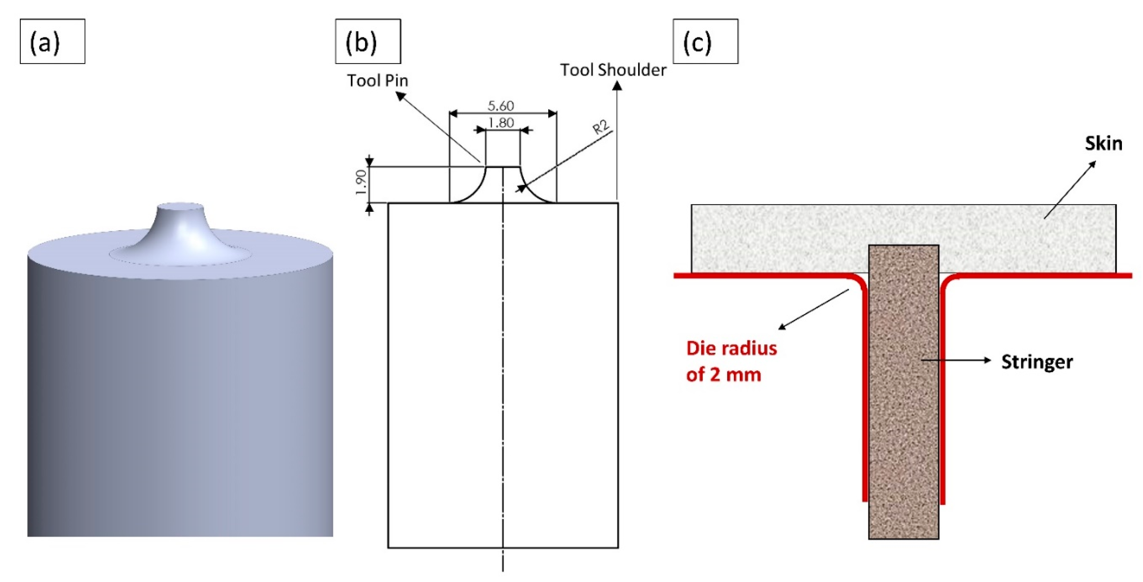
2. Materials and Methods
3. Results and Discussion
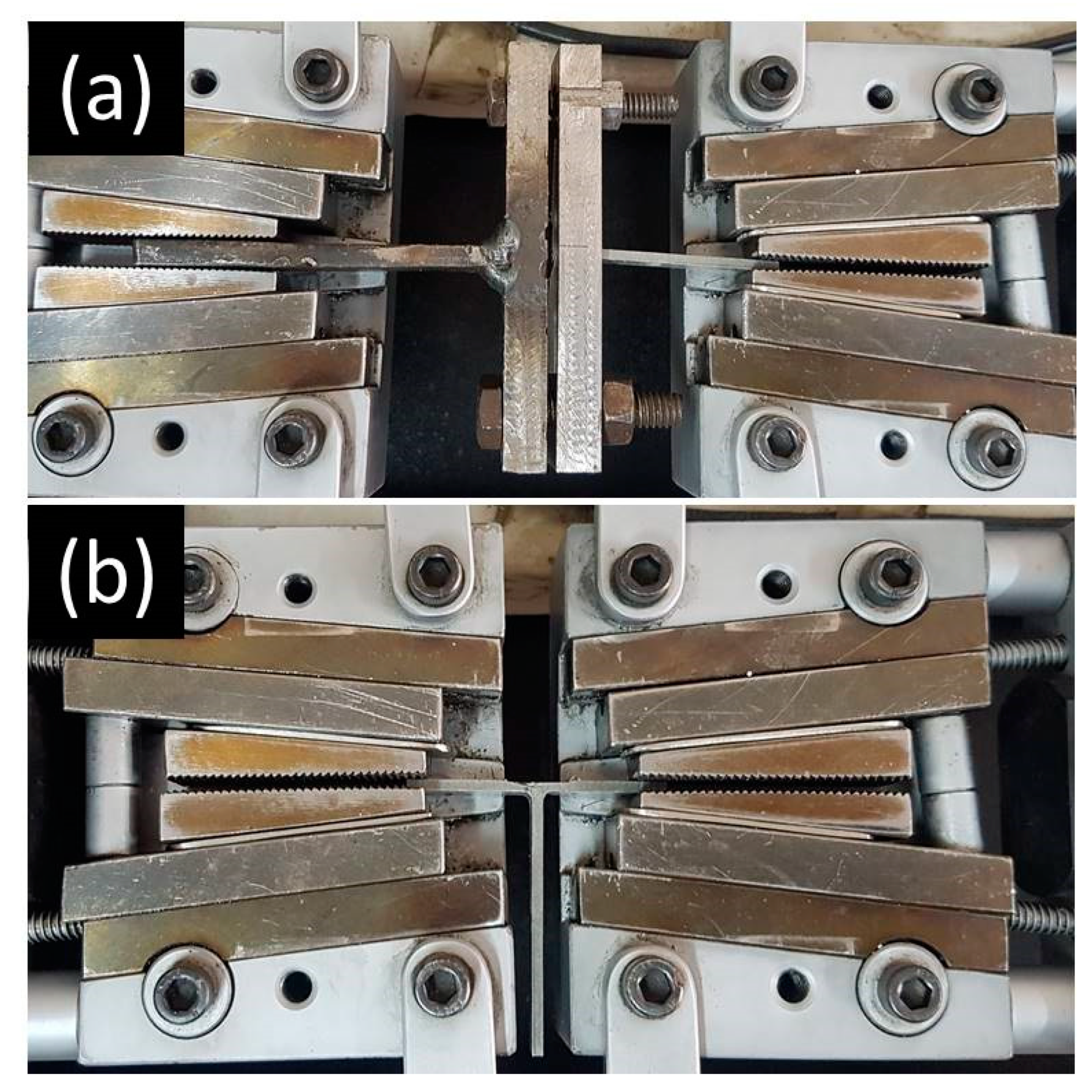
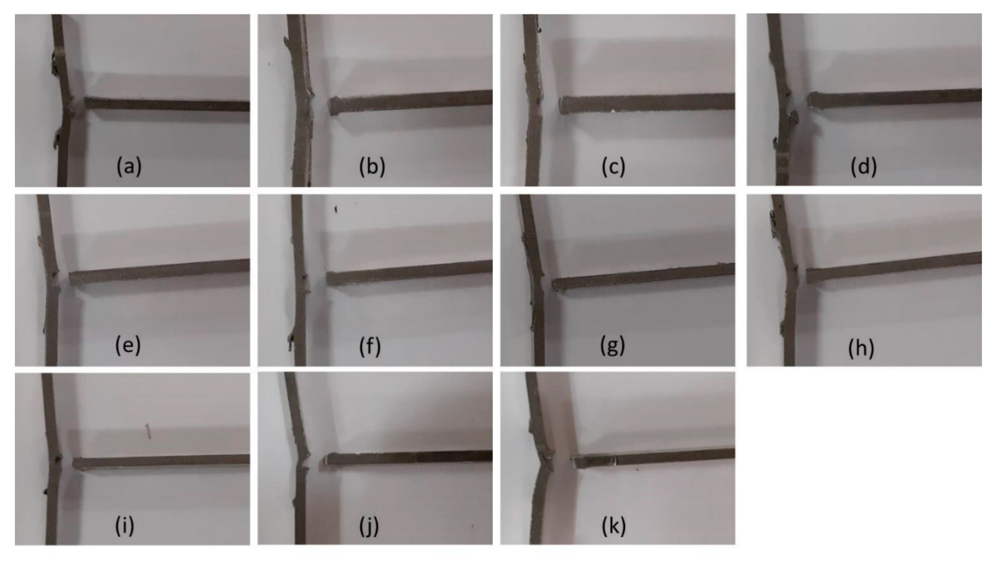
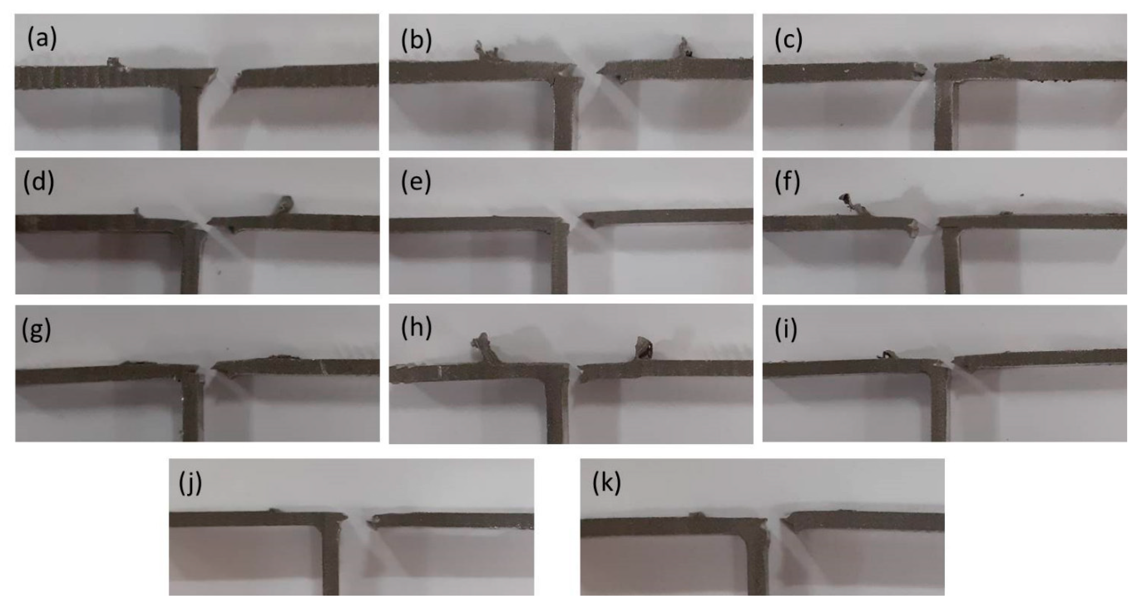
3.1. Tensile Strength
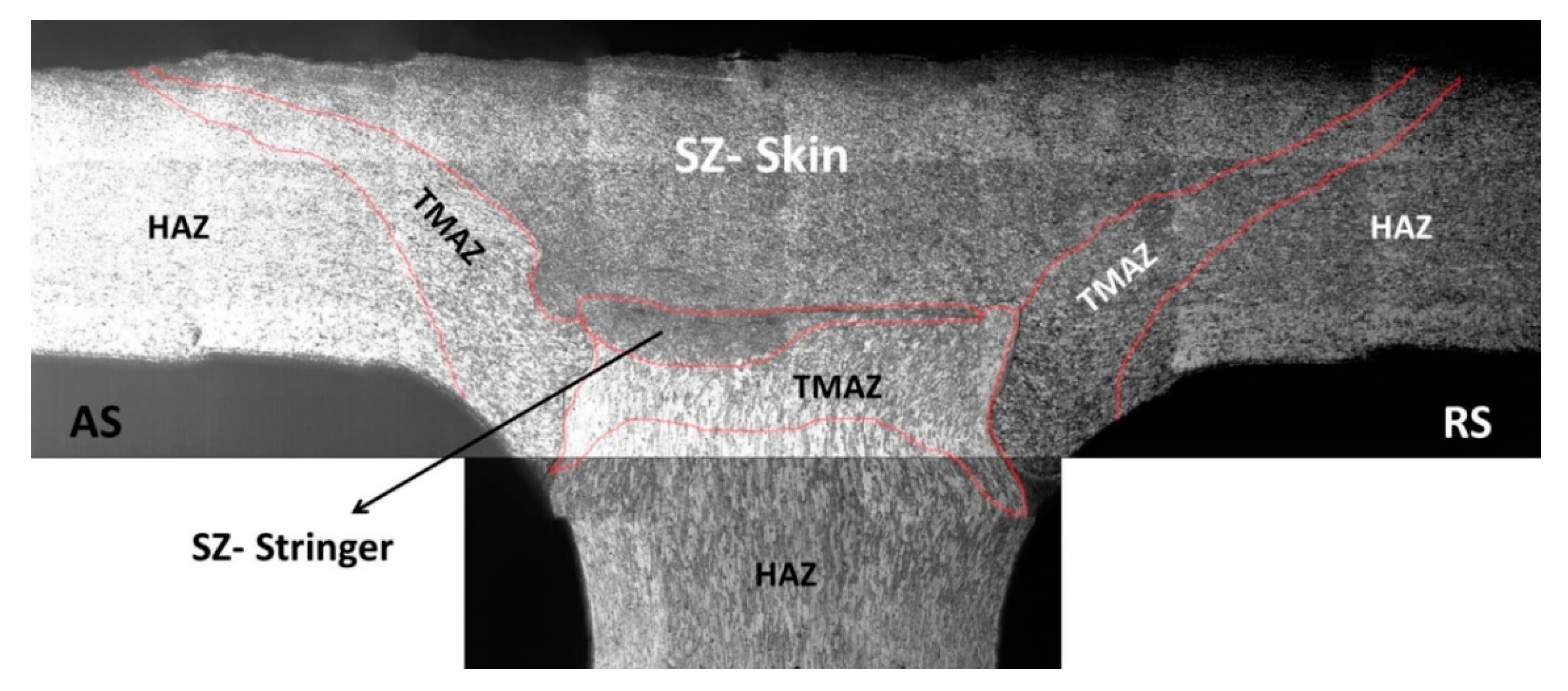
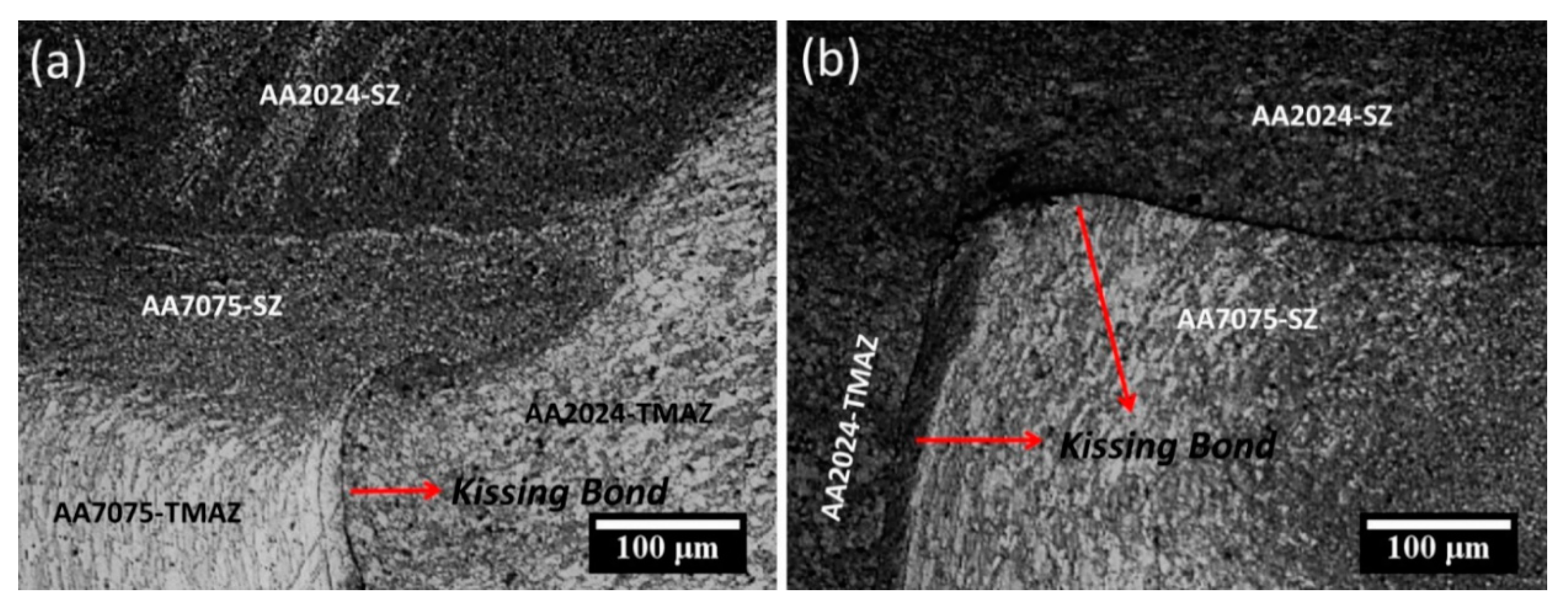
3.2. Microstructure
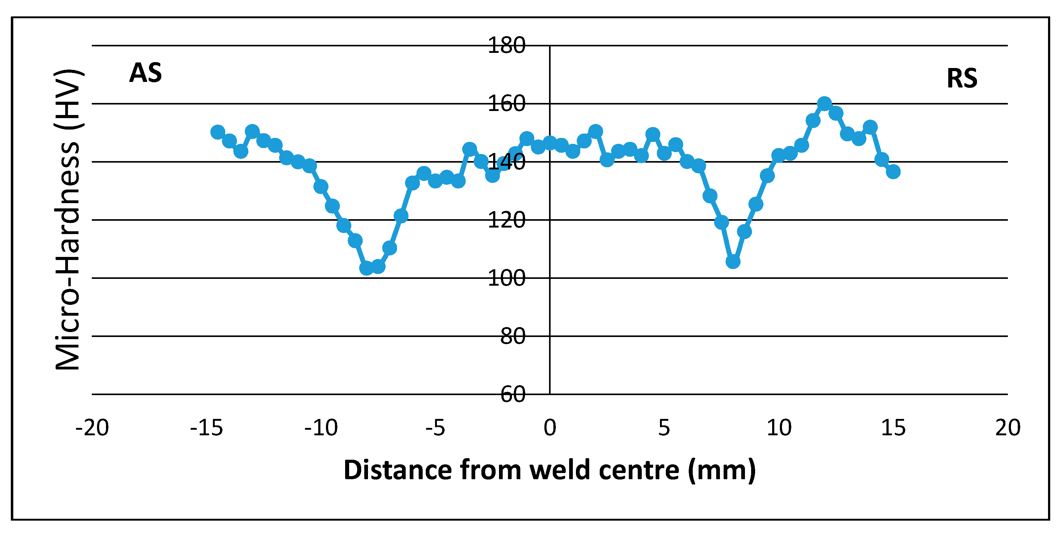
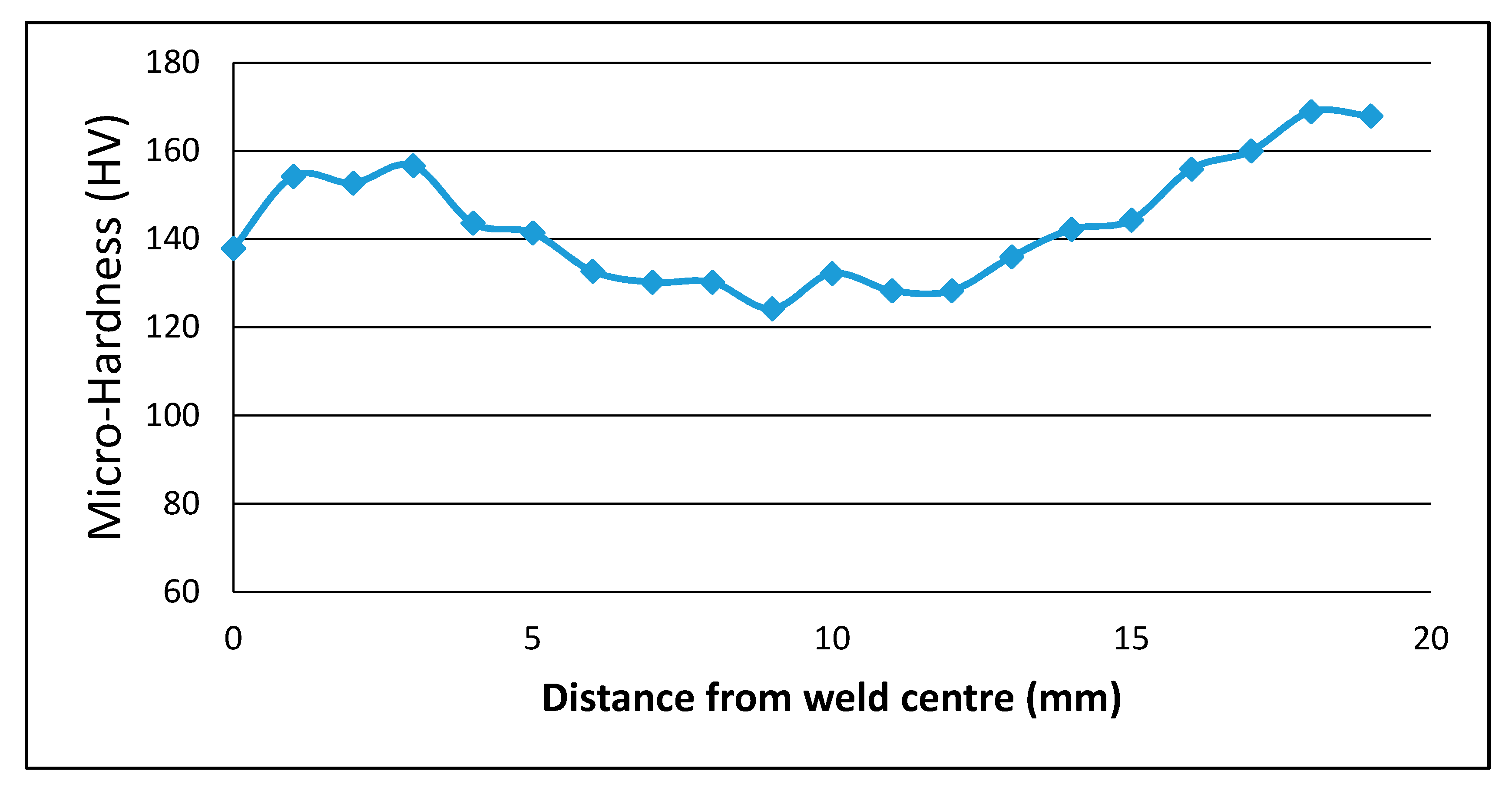
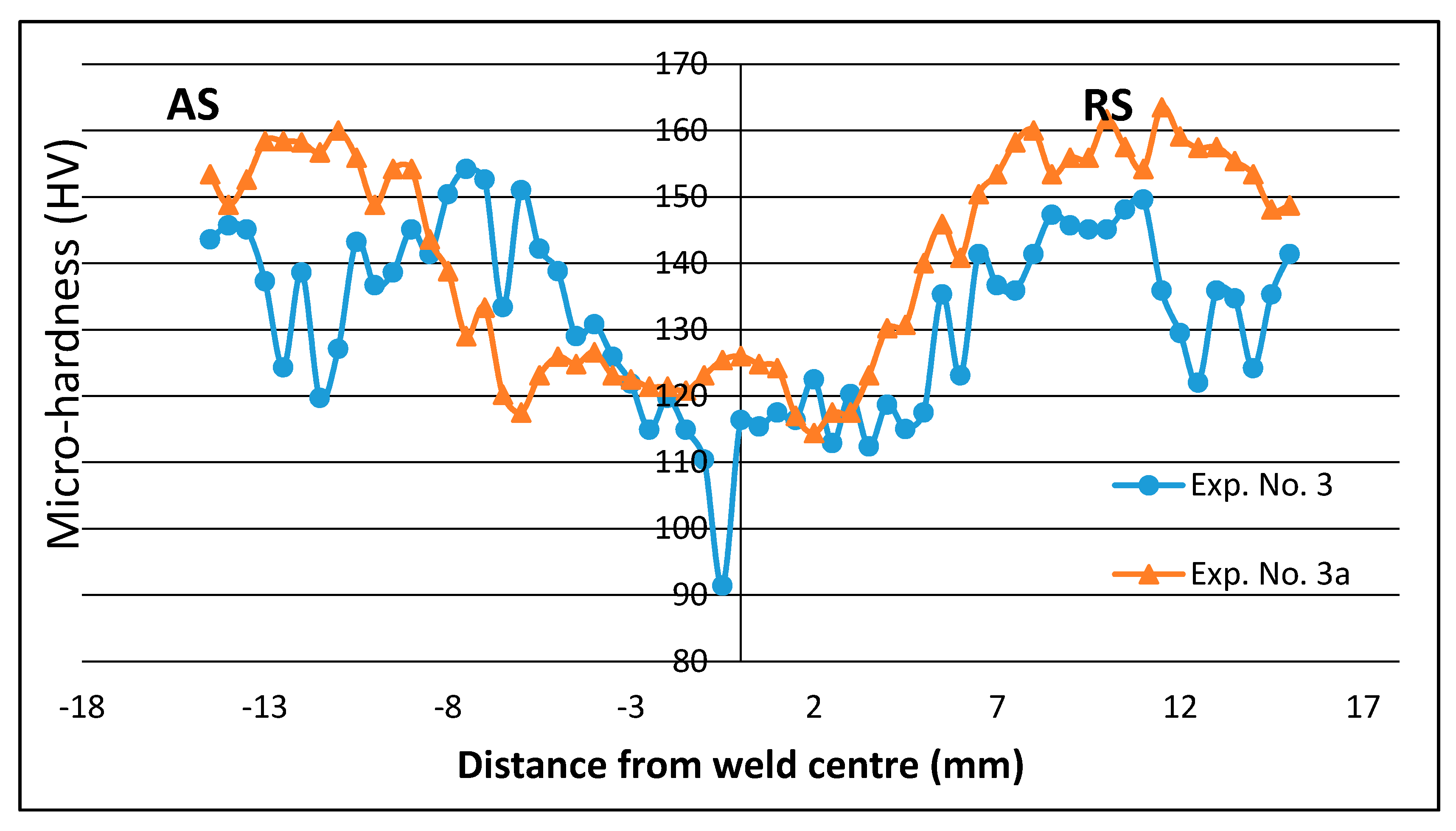
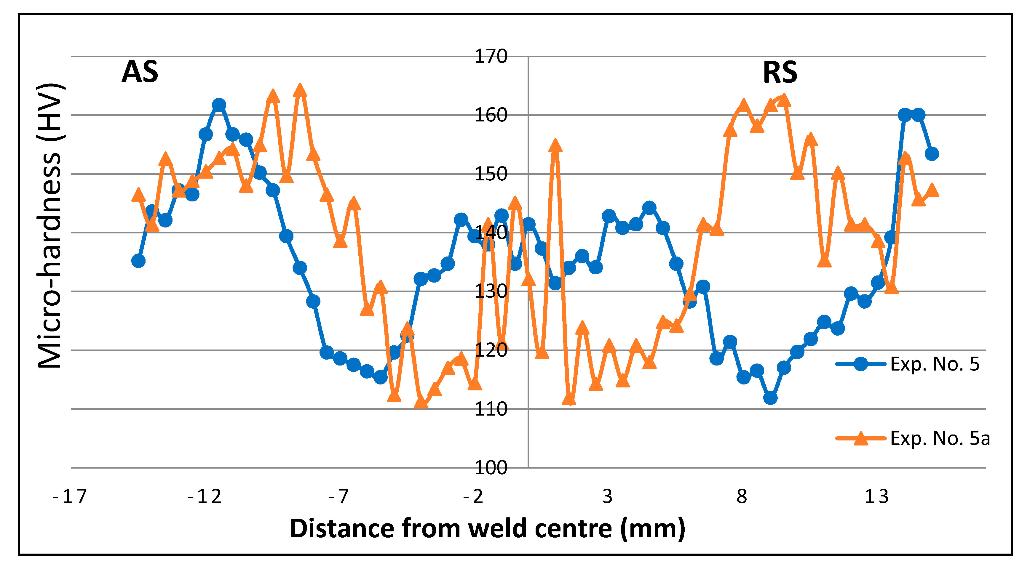
3.3. Micro-Hardness
4. Conclusions
Author Contributions
Funding
Acknowledgments
Conflicts of Interest
References
- He, D.; Yang, K.; Li, M.; Guo, H.; Li, N.; Lai, R.; Ye, S. Comparison of single and double pass friction stir welding of skin–stringer aviation aluminium alloy. Sci. Technol. Weld. Join. 2013, 18, 610–615. [Google Scholar] [CrossRef]
- Teng, T.-L.; Fung, C.-P.; Chang, P.-H.; Yang, W.-C. Analysis of residual stresses and distortions in T-joint fillet welds. Int. J. Press. Vessel. Pip. 2001, 78, 523–538. [Google Scholar] [CrossRef]
- Mashiri, F.R.; Zhao, X.-L.; Grundy, P. Stress concentration factors and fatigue behaviour of welded thin-walled CHS–SHS T-joints under in-plane bending. Eng. Struct. 2004, 26, 1861–1875. [Google Scholar] [CrossRef]
- Tavares, S.M.O.; Castro, R.A.S.; Richter-Trummer, V.; Vilaça, P.; Moreira, P.M.G.P.; de Castro, P.M.S.T. Friction stir welding of T-joints with dissimilar aluminium alloys: Mechanical joint characterisation. Sci. Technol. Weld. Join. 2010, 15, 312–318. [Google Scholar] [CrossRef]
- Mabuwa, S.; Msomi, V. Review on Friction Stir Processed TIG and Friction Stir Welded Dissimilar Alloy Joints. Metals 2020, 10, 142. [Google Scholar] [CrossRef]
- Hannard, F.; Castin, S.; Maire, E.; Mokso, R.; Pardoen, T.; Simar, A. Ductilization of aluminium alloy 6056 by friction stir processing. Acta Mater. 2017, 130, 121–136. [Google Scholar] [CrossRef]
- Ma, Z.Y.; Feng, A.H.; Chen, D.L.; Shen, J. Recent Advances in Friction Stir Welding/Processing of Aluminum Alloys: Microstructural Evolution and Mechanical Properties. Crit. Rev. Solid State Mater. Sci. 2018, 43, 269–333. [Google Scholar] [CrossRef]
- Vilaça, P.; Santos, J.P.; Góis, A.; Quintino, L. Joining Aluminium Alloys Dissimilar in Thickness by Friction Stir Welding and Fusion Processes. Weld. World 2005, 49, 56–62. [Google Scholar] [CrossRef]
- Prime, M.B.; Gnäupel-Herold, T.; Baumann, J.A.; Lederich, R.J.; Bowden, D.M.; Sebring, R.J. Residual stress measurements in a thick, dissimilar aluminum alloy friction stir weld. Acta Mater. 2006, 54, 4013–4021. [Google Scholar] [CrossRef]
- Mishra, R.S.; Ma, Z.Y. Friction stir welding and processing. Mater. Sci. Eng. R Rep. 2005, 50, 1–78. [Google Scholar] [CrossRef]
- Fahimpour, V.; Sadrnezhaad, S.K.; Karimzadeh, F. Corrosion behavior of aluminum 6061 alloy joined by friction stir welding and gas tungsten arc welding methods. Mater. Des. 2012, 39, 329–333. [Google Scholar] [CrossRef]
- Kroninger, H.R.; Reynolds, A.P. R-curve behaviour of friction stir welds in aluminium-lithium alloy 2195. Fatigue Fract. Eng. Mater. Struct. 2002, 25, 283–290. [Google Scholar] [CrossRef]
- Shercliff, H.R.; Russell, M.J.; Taylor, A.; Dickerson, T.L. Microstructural modelling in friction stir welding of 2000 series aluminium alloys. Mech. Ind. 2005, 6, 25–35. [Google Scholar] [CrossRef]
- Gupta, R.K.; Das, H.; Pal, T.K. Influence of Processing Parameters on Induced Energy, Mechanical and Corrosion Properties of FSW Butt Joint of 7475 AA. J. Mater. Eng. Perform. 2012, 21, 1645–1654. [Google Scholar] [CrossRef]
- Kadlec, M.; Růžek, R.; Nováková, L. Mechanical behaviour of AA 7475 friction stir welds with the kissing bond defect. Int. J. Fatigue 2015, 74, 7–19. [Google Scholar] [CrossRef]
- Arora, K.S.; Pandey, S.; Schaper, M.; Kumar, R. Effect of process parameters on friction stir welding of aluminum alloy 2219-T87. Int. J. Adv. Manuf. Technol. 2010, 50, 941–952. [Google Scholar] [CrossRef]
- Sheng, X.; Li, K.; Wu, W.; Yang, Y.; Liu, Y.; Zhao, Y.; He, G. Microstructure and Mechanical Properties of Friction Stir Welded Joint of an Aluminum Alloy Sheet 6005A-T4. Metals 2019, 9, 1152. [Google Scholar] [CrossRef]
- Vidal, C.; Infante, V. Fatigue behavior of friction stir-welded joints repaired by grinding. J. Mater. Eng. Perform. 2004, 23, 1340–1349. [Google Scholar] [CrossRef]
- Cabibbo, M.; Forcellese, A.; Santecchia, E.; Paoletti, C.; Spigarelli, S.; Simoncini, M. New Approaches to Friction Stir Welding of Aluminum Light-Alloys. Metals 2020, 10, 233. [Google Scholar] [CrossRef]
- Cederqvist, L.; Reynolds, A. Factors affecting the properties of friction stir welded aluminum lap joints. Weld. J. 2001, 80, 281-s. [Google Scholar]
- Cavaliere, P.; Nobile, R.; Panella, F.W.; Squillace, A. Mechanical and microstructural behaviour of 2024–7075 aluminium alloy sheets joined by friction stir welding. Int. J. Mach. Tools Manuf. 2006, 46, 588–594. [Google Scholar] [CrossRef]
- Zhao, Y.; Zhou, L.; Wang, Q.; Yan, K.; Zou, J. Defects and tensile properties of 6013 aluminum alloy T-joints by friction stir welding. Mater. Des. 2014, 57, 146–155. [Google Scholar] [CrossRef]
- Boz, M.; Kurt, A. The influence of stirrer geometry on bonding and mechanical properties in friction stir welding process. Mater. Des. 2004, 25, 343–347. [Google Scholar] [CrossRef]
- Fratini, L.; Micari, F.; Squillace, A.; Giorleo, G. Experimental Characterization of FSW T-Joints of Light Alloys. Key Eng. Mater. 2007, 344, 751–758. [Google Scholar] [CrossRef]
- Krasnowski, K. Experimental Study of FSW T-joints of EN-AW 6082-T6 and Their Behaviour Under Static Loads. Arab. J. Sci. Eng. 2014, 39, 9083–9092. [Google Scholar] [CrossRef]
- Sato, Y.S.; Takauchi, H.; Park, S.H.C.; Kokawa, H. Characteristics of the kissing-bond in friction stir welded Al alloy 1050. Mater. Sci. Eng. A 2005, 405, 333–338. [Google Scholar] [CrossRef]
- Brown, R.; Tang, W.; Reynolds, A.P. Multi-pass friction stir welding in alloy 7050-T7451: Effects on weld response variables and on weld properties. Mater. Sci. Eng. A 2009, 513–514, 115–121. [Google Scholar] [CrossRef]
- Sathari, N.A.; Shah, L.H.; Razali, A.R. Investigation of single-pass/double-pass techniques on friction stir welding of aluminium. J. Mech. Eng. Sci. 2014, 7, 1053–1061. [Google Scholar] [CrossRef]
- Osman, N.; Sajuri, Z.; Baghdadi, A.H.; Omar, M.Z. Effect of Process Parameters on Interfacial Bonding Properties of Aluminium–Copper Clad Sheet Processed by Multi-Pass Friction Stir-Welding Technique. Metals 2019, 9, 1159. [Google Scholar] [CrossRef]
- Erbslöh, K.; Dalle Donne, C.; Lohwasser, D. Friction Stir Welding of T-Joints. Mater. Sci. Forum 2003, 426–432, 2965–2970. [Google Scholar] [CrossRef]
- Chen, Y.; Li, H.; Wang, X.; Ding, H.; Zhang, F. A Comparative Investigation on Conventional and Stationary Shoulder Friction Stir Welding of Al-7075 Butt-Lap Structure. Metals 2019, 9, 1264. [Google Scholar] [CrossRef]
- Information Provided by The Aluminum Association, Inc. from Aluminum Standards and Data 2000 and/or International Alloy Designations and Chemical Composition Limits for Wrought Aluminum and Wrought Aluminum Alloys (Revised 2001). Available online: http://asm.matweb.com/search/SpecificMaterial.asp?bassnum=MA2024T3 (accessed on 17 April 2020).
- Bauccio, M. (Ed.) ASM Metals Reference Book, 3rd ed.; ASM International: Materials Park, OH, USA, 1993. [Google Scholar]
- Metals Handbook, 10th ed.; Vol.2—Properties and Selection: Nonferrous Alloys and Special-Purpose Materials; ASM International: Materials Park, OH, USA, 1990.
- Howard, E.B.; Timothy, L.G. (Eds.) Metals Handbook; American Society for Metals: Materials Park, OH, USA, 1985. [Google Scholar]
- John, M.T.H.; HO, C.Y. (Eds.) Structural Alloys Handbook, 1996th ed.; CINDAS/Purdue University: West Lafayette, IN, USA, 1996. [Google Scholar]
- Fratini, L.; Buffa, G.; Shivpuri, R. Influence of material characteristics on plastomechanics of the FSW process for T-joints. Mater. Des. 2009, 30, 2435–2445. [Google Scholar] [CrossRef]
- Arora, A.; Mehta, M.; De, A.; DebRoy, T. Load bearing capacity of tool pin during friction stir welding. The Int. J. Adv. Manuf. Technol. 2012, 61, 911–920. [Google Scholar] [CrossRef]
- Pishevar, M.R.; Mohandesi, J.A.; Omidvar, H.; Safarkhanian, M.A. Influences of Friction Stir Welding Parameters on Microstructural and Mechanical Properties of AA5456 (AlMg5) at Different Lap Joint Thicknesses. J. Mater. Eng. Perform. 2015, 24, 3835–3844. [Google Scholar] [CrossRef]
- Chen, Y.; Ding, H.; Li, J.-Z.; Zhao, J.-W.; Fu, M.-J.; Li, X.-H. Effect of welding heat input and post-welded heat treatment on hardness of stir zone for friction stir-welded 2024-T3 aluminum alloy. Trans. Nonferrous Met. Soc. China 2015, 25, 2524–2532. [Google Scholar] [CrossRef]
- Leitao, C.; Leal, R.M.; Rodrigues, D.M.; Loureiro, A.; Vilaça, P. Mechanical behaviour of similar and dissimilar AA5182-H111 and AA6016-T4 thin friction stir welds. Mater. Des. 2009, 30, 101–108. [Google Scholar] [CrossRef]
- Khodir, S.A.; Shibayanagi, T. Friction stir welding of dissimilar AA2024 and AA7075 aluminum alloys. Mater. Sci. Eng. B 2008, 148, 82–87. [Google Scholar] [CrossRef]
- Yan, Z.; Liu, X.; Fang, H. Effect of Sheet Configuration on Microstructure and Mechanical Behaviors of Dissimilar Al–Mg–Si/Al–Zn–Mg Aluminum Alloys Friction Stir Welding Joints. J. Mater. Sci. Technol. 2016, 32, 1378–1385. [Google Scholar] [CrossRef]


| Element | Al | Cu | Mg | Si | Fe | Ni | Mn | Zn | Pb | Sn | Ti | Cr | V |
|---|---|---|---|---|---|---|---|---|---|---|---|---|---|
| Wt.% | Balance | 4.62 | 1.10 | 0.062 | 0.133 | 0.014 | 0.438 | 0.03 | 0.004 | 0.012 | 0.027 | <0.005 | 0.009 |
| Element | Al | Cu | Mg | Si | Fe | Ni | Mn | Zn | Pb | Sn | Ti | Cr | V |
|---|---|---|---|---|---|---|---|---|---|---|---|---|---|
| Wt.% | Balance | 1.6 | 2.74 | 0.051 | 0.127 | <0.008 | 0.022 | 5.5 | <0.001 | 0.005 | 0.024 | 0.218 | 0.008 |
| Property | Aluminium Alloy | |
|---|---|---|
| AA2024-T3 | AA7075-T6 | |
| Ultimate Tensile Strength (MPa) | 437 | 517 |
| Vickers Hardness (HV) | 168 | 225 |
| Incipient melting-liquidus Temperature (°C) | 502–638 °C | 477–635 °C |
| Thermal Conductivity (W/(m·K)) | 121 | 130 |
| Specific heat capacity (J/(g·°C)) | 0.875 | 0.96 |
| Experimental Design | Experiment Number | Process Parameter Level | ||
|---|---|---|---|---|
| Shoulder Diameter | Rotational Speed | Welding Speed | ||
| Taguchi L9 | 1 | 14 | 710 | 40 |
| 2 | 16 | 710 | 50 | |
| 3 | 12 | 900 | 50 | |
| 4 | 12 | 560 | 40 | |
| 5 | 16 | 560 | 63 | |
| 6 | 14 | 900 | 63 | |
| 7 | 14 | 560 | 50 | |
| 8 | 12 | 710 | 63 | |
| 9 | 16 | 900 | 40 | |
| Second Pass | 3a | 12 | 710 | 63 |
| 5a | 12 | 710 | 63 | |
| Exp. No. | Process Parameters | Tensile Properties along Skin | Tensile Properties along Stringer | ||||||
|---|---|---|---|---|---|---|---|---|---|
| N (rpm) | v (mm/min) | D (mm) | Tensile Strength (MPa) | Elongation (%) | Fracture Location | Tensile Strength (MPa) | Elongation (%) | Fracture Location | |
| 4 | 560 | 40 | 12 | 197 | 6.7 | SZ | 45 | 1.4 | SZ |
| 7 | 560 | 50 | 14 | 216 | 7.3 | SZ | 83 | 3.1 | SZ |
| 5 | 560 | 63 | 16 | 177 | 6.8 | SZ | 85 | 2.7 | SZ |
| 1 | 710 | 40 | 14 | 330 | 8.4 | RS-TMAZ | 71 | 2.8 | SZ |
| 2 | 710 | 50 | 16 | 303 | 10.9 | SZ | 108 | 3.2 | SZ |
| 8 | 710 | 63 | 12 | 258 | 10.2 | RS-KB | 155 | 4.3 | SZ |
| 9 | 900 | 40 | 16 | 209 | 6.9 | SZ | 42 | 1.8 | SZ |
| 3 | 900 | 50 | 12 | 150 | 6.2 | Tunnel | 53 | 2.2 | SZ |
| 6 | 900 | 63 | 14 | 265 | 7.0 | AS-KB | 63 | 2.3 | SZ |
| 3a | 710 | 40 | 14 | 307 | 13.6 | RS-KB | 177 | 3.4 | SZ |
| 5a | 710 | 40 | 14 | 273 | 7.7 | RS-KB | 165 | 5.6 | SZ |
© 2020 by the authors. Licensee MDPI, Basel, Switzerland. This article is an open access article distributed under the terms and conditions of the Creative Commons Attribution (CC BY) license (http://creativecommons.org/licenses/by/4.0/).
Share and Cite
Abidi, M.H.; Ali, N.; Ibrahimi, H.; Anjum, S.; Bajaj, D.; Siddiquee, A.N.; Alkahtani, M.; Rehman, A.U. T-FSW of Dissimilar Aerospace Grade Aluminium Alloys: Influence of Second Pass on Weld Defects. Metals 2020, 10, 525. https://doi.org/10.3390/met10040525
Abidi MH, Ali N, Ibrahimi H, Anjum S, Bajaj D, Siddiquee AN, Alkahtani M, Rehman AU. T-FSW of Dissimilar Aerospace Grade Aluminium Alloys: Influence of Second Pass on Weld Defects. Metals. 2020; 10(4):525. https://doi.org/10.3390/met10040525
Chicago/Turabian StyleAbidi, Mustufa Haider, Nabeel Ali, Hashmatullah Ibrahimi, Saquib Anjum, Dhruv Bajaj, Arshad Noor Siddiquee, Mohammed Alkahtani, and Ateekh Ur Rehman. 2020. "T-FSW of Dissimilar Aerospace Grade Aluminium Alloys: Influence of Second Pass on Weld Defects" Metals 10, no. 4: 525. https://doi.org/10.3390/met10040525
APA StyleAbidi, M. H., Ali, N., Ibrahimi, H., Anjum, S., Bajaj, D., Siddiquee, A. N., Alkahtani, M., & Rehman, A. U. (2020). T-FSW of Dissimilar Aerospace Grade Aluminium Alloys: Influence of Second Pass on Weld Defects. Metals, 10(4), 525. https://doi.org/10.3390/met10040525