Article

Compound Layer Design for Deep Nitrided Gearings

Leibniz-Institut für Werkstofforientierte Technologien-IWT, Badgasteiner Straße 3, 28359 Bremen, Germany and MAPEX, Center for Materials and Processes, Universität Bremen, Bibliothekstraße 1, 28359 Bremen, Germany
*
Author to whom correspondence should be addressed.
Metals 2020, 10(4), 455; https://doi.org/10.3390/met10040455
Submission received: 2 March 2020 / Revised: 26 March 2020 / Accepted: 27 March 2020 / Published: 31 March 2020
(This article belongs to the Special Issue Heat Treatment of Steels)

Abstract

:
Deep nitriding is used to obtain a nitriding hardness depth beyond 0.6 mm. The long nitriding processes, which are necessary to reach the high nitriding hardness depths, mostly have a negative influence on the hardness and strength of the nitrided layer as well as on the bulk material. The compound layer often is considered less, because in most practical cases, it is removed mechanically after nitriding, to avoid spalling in service. However, in former investigations, it was shown, that thick and compact compound layers have the potential for high flank load capacity of gears. The investigations focus on the simultaneous formation of a high nitriding depth and a thick and compact compound layer. Beside the preservation of the strength, a challenge is to control the porosity of the compound layer, which should be as low as possible. The investigations were carried out using the common nitriding and heat treatable mild steel 31CrMoV9, which is often used for gear applications. The article gives an insight on the development of multistage nitriding processes studied by short- and long-term experiments aiming for a specific compound layer build-up with low porosity and high strength of the nitride layer and core material.

1. Introduction

High performance gears are usually subjected to heat treatment in order to achieve optimum performance for the respective application. Thermochemical surface layer heat treatment, such as case hardening, carbonitriding, nitriding or nitrocarburizing are common treatments, since the highest stress is in the surface layer of the teeth and a tough core is positive for the service behavior [1]. Studies have shown that nitriding treatment can improve the load-bearing properties of gears with regard to different stresses. König et al. provide an overview of nitriding applications for gearings [2].
The necessary hardening depth of the surface layer depends on the normal modulus of the gearing [3]. For nitriding, a nitriding hardening depth of approximately 0.6 mm is regarded as the economic limit value. Therefore case hardening is frequently used for larger gears, since higher case depths can be achieved in a shorter time. Nevertheless, nitriding offers some process-related advantages compared to case hardening, such as better protection against scuffing, wear and corrosion, higher surface hardness, a temperature-stable surface layer for use at higher temperatures, as well as less dimensional and shape changes and thus generally no need for reworking [4].
Deep nitriding differs from conventional nitriding in aiming higher nitriding hardness depths of approximately 0.8–1.0 mm. In order to achieve those nitriding hardness depths, long nitriding periods and/or high nitriding temperatures are necessary, which leads to losses of strength in the nitriding layer and in the core. In order to minimize these losses in strength caused by tempering effects during nitriding, the maximum possible nitriding temperature is limited depending on the material [5].
Investigations on deep nitriding were already carried out in the 1980s [6], when the nitriding plant technology was not yet sufficiently developed to enable controlled and reproducible nitriding treatments to be carried out in gas or plasma. For this reason, more recent investigations concern also nitriding processes for achieving high nitriding hardness depths [4,7,8,9]. In [4] material-oriented two-stage processes for deep nitriding were developed with the aim of achieving high nitriding hardness depths with the highest possible strength. These processes were carried out according to the two-stage principle developed by Floe [10,11], where a closed compound layer was formed during the first stage. The temperature was kept low at 520 °C in order to obtain finely distributed precipitates in the diffusion layer. In the second stage at elevated temperature, diffusion was carried out into the depth and the growth of the compound layer was restricted by a low nitriding index. By this process control, negative effects on the strength of the material could be kept within limits and stress-compatible nitriding layers with high nitriding hardness depths with sufficient strength of the base material could be reliably and reproducibly produced by modern process technology.
Nitriding increases the rolling contact fatigue life of gears, whereas the generated compressive residual stresses within the diffusion layer are responsible for the enhancement of the fatigue strength [12,13]. Until now, the primary objective of nitriding process development was to achieve high nitriding hardness depths with economical process duration and little attention has been paid to the compound layer during. In random tests on the tooth flank load-bearing capacity, one of the investigated variants, which had a comparatively thick, compact compound layer due to a higher nitriding temperature, showed particularly good load-bearing capacity behavior. It was remarkable that the compound layer remained almost undamaged after the load-tests at high load levels, whereas in the other tested variants with a thinner compound layer, defects in the compound layer occurred after only a few load cycles [14]. Additionally the authors of [15] showed in their work, that a control of the nitriding parameters is necessary because the crystalline structure profile of the compound layer is important for the gear performance.
The composition of the compound layer (γ’-nitride/ε-nitride/alloying element nitrides) and the shape of the porous zone also play a significant role in the tribological load-bearing capacity [16]. The ε-nitride has a higher hardness than the γ’-nitride and due to its hexagonal structure, the ε-nitride has a low number of sliding systems, which prevents the wear partners from approaching each other over an area down to atomic distances. For this reason, the adhesion tendency of ε-nitride layers is low. The pore content and the pore distribution and size also have an influence on the wear behavior. Depending on the wear load, sometimes γ’-layers show better wear properties and sometimes thin, slightly porous ε-compound layers [17,18,19].
The current investigations deal with the simultaneous achievement of high nitriding hardness depths and a thick, compact compound layer. In addition to maintaining the strength properties, another challenge is to ensure that the compound layer does not become too porous.

2. Materials and Methods

2.1. Reference State

The deep nitrided material 32CDV13 (0.32% C, 0.33% Si, 0.55% Mn, 3.00% Cr, 0.90% Mo and 0.29% V) showed a remarkable load-bearing potential in [14]. The gears were deep nitrided in a material-oriented two-stage treatment in a controlled gas nitriding process with steel retort. In the first stage at 520 °C in 15 h with a nitriding potential of KN = 1, a compound layer and fine nitride precipitates were formed in the first approximately 0.25 mm of the diffusion zone. In the second stage, the temperature was increased to 570 °C for 130 h and at the same time the nitriding potential was reduced to KN = 0.5. The second stage was mainly used for rapid diffusion of the nitrogen into the material in order to achieve the desired nitriding hardness depth.
The compound layer of the reference material 32CDV13 formed on the tooth flank is shown in Figure 1. Table 1 shows the compound layer thickness (CLT), the thickness of the porous zone (CLTP) and nitriding hardness depth (NHD) averaged over the tooth area. Despite the low nitriding potential of KN = 0.5 in the diffusion phase, a relatively thick compound layer has been formed due to the comparatively high temperature and long duration required for nitriding.
The nitrogen and carbon profiles of the reference compound layer determined by Glow Discharge Optical Emission Spectroscopy (GD-OES) are shown in Figure 2. In the area of the porous zone, the nitrogen concentration of approximately 9–9.5 mass-% was slightly higher than in the compact area of the compound layer below. Here the nitrogen concentration was about 6.5 mass-%. Taking into account the alloying elements, which also bind nitrogen as nitride, it can be assumed that the compound layer consists mainly of γ’-nitride and that in the area of the porous zone ε-nitrides have also been formed. A X-ray phase analysis with Cr Kα radiation (surface measurement) showed a compound layer composition of approximately 14% ε-nitride and approximately 86% γ’-nitride, which confirms the considerations made on the basis of the nitrogen profile.

2.2. Investigated Material

The frequently used nitriding and tempering steel 31CrMoV9 (0.33% C, 0.29% Si, 0.57% Mn, 2.41% Cr, 0.16% Mo and 0.12% V) served as the investigation material. The material was quenched and tempered prior to nitriding. For this purpose, the material was austenitized at 950 °C, quenched in oil and tempered for 2 h at 630 °C. The hardening temperature, which is untypical for the material 31CrMoV9, was selected in accordance with the practice for the reference material 32CDV13 in order to produce a similar microstructural state to that of the reference material. Compared to a classical hardening at 870 °C and tempering at 630 °C, the higher austenitizing temperature resulted in a hardness that was about 30 HV1 higher. The reason for the higher hardness was assumed to be that more carbon was dissolved at the higher austenitizing temperature due to the dissolution of low chromium-containing precipitates, and that the carbides were finely precipitated again during subsequent tempering.

2.3. Nitriding Treatments

The nitriding and nitrocarburizing treatments were carried out in a gas nitriding plant with controlled nitriding and carburizing potential. The heating was carried out under an ammonia atmosphere to activate the sample surface. The cooling after nitriding was also carried out with the addition of ammonia (phase-controlled cooling) in order to avoid nitrogen effusion and subsequent denitration at the end of the process. Table 2 gives an overview of the parameter variations carried out in the treatments.
With the aim of gaining an understanding of the relationship between nitriding and carburizing potential and compound layer structure and phase composition, short-term treatments were initially carried out. By a specific variation of the nitriding and carburizing potential different compound layers could be produced by nitriding and nitrocarburizing. The temperature of 520 °C and the duration of 15 h were chosen for the short-term tests analogous to the first stage of the two-stage treatment of the reference material. In one treatment, the temperature of 520 °C was increased to 550 °C for nitrocarburizing, as nitrocarburizing is more likely to be carried out at temperatures of 550–590 °C. The short-term treatments were intended to provide assistance in selecting the process parameters for the long-term treatments.
The long-term treatments were carried out with two different strategies: In one-stage treatments, a continuous built-up compound layer structure was aimed, whereas in the two-stage treatments the compound layer was designed in an extra process stage prior to or after the diffusion layer was built up. The nitriding hardness depth was aimed to be approximately 0.8 mm after all long-term treatments.
The one-stage treatment with the nitriding potential KN = 0.5 corresponds to the diffusion phase of the process developed for the material 31CrMoV9 in [4,14] and was also used as a diffusion phase in the two-stage treatments. In two further one-stage treatments, a thicker compound layer was aimed at by increasing the nitriding potential. The tempering parameter according to Hollomon-Jaffe [20] was H = 17.9 for all 170-h treatments at 530 °C and was thus still below the critical value of about H = 18, which, according to Hoja et al. would lead to a decrease of strength [4,5]. Since in the tests carried out in the past with the material 32CDV13 the thick compound layer was formed at a higher temperature (570 °C), a one-stage treatment at 550 °C was also carried out. With the temperature increase, the nitriding time was shortened accordingly to achieve a similar nitriding hardness depth. With H = 18.2, the tempering parameter of the 120-hour single-stage test at 550 °C was slightly above H = 18, which means that after this process a decrease in strength in the nitriding layer and in the base material is to be expected.
In the previous investigations [4], the two-stage treatments used the principle developed by Floe, according to which a compound layer is first built up and its growth is suppressed or restricted in the further process [10,11]. A focus of the present investigations was therefore on the sequence of the process stages. The compound layer build-up after the diffusion layer was built up had the goal of forming a more compact, less porous compound layer.

2.4. Characterization of the Compound Layer

The thickness of the compound layer and the porous zone was evaluated according to the test specification of the Arbeitsgemeinschaft Wärmebehandlung + Werkstofftechnik e. V. (AWT) [21] on the metallographic cross-section taken from coupon samples separated by spark erosion. All sections were etched with Nital and images were taken at 1000× magnification via light microscope Leica DM6000 (Leica, Wetzlar, Germany). The average compound layer and thickness of the porous zone were determined by measuring at ten points on three micrographs. In addition to documenting the compound layer, the nitriding hardness depth was also determined on the cross section in accordance with DIN 50190-3. The composition of the compound layers was determined using glow discharge spectroscopy (GD-OES, LECO GDS 750A, SN 3030, St. Joseph, MI, USA) and X-ray methods. For this purpose, nitrogen and carbon depth profiles were recorded to a depth of about 50–70 µm. Based on the nitrogen and carbon content, the thickness and composition of the compound layer can be estimated, since the (carbo-)nitride phases have different nitrogen and carbon contents. In addition, X-ray diffraction spectra with Cr-Kα radiation were recorded and the proportions of ε- and γ’-nitride were determined using the Rietveld method. The Rietveld method involves fitting the entire spectrum. The diffraction spectrum of a polycrystalline substance is regarded as a mathematical function of the angle of diffraction, which also depends on the crystal structure. Starting from an initial model of the atomic arrangement, structural and instrumental parameters are continually refined. Since the penetration depth of the X-rays, defined as the depth to which the radiation intensity drops to 1/e, is limited to about 10 µm and the information about the phase fractions according to an exponential function weighted according to depth was included in the measured value, the information obtained in this way could be seen as an average phase composition for thicker compound layers in addition to the GD-OES measurements and the thermodynamic calculations.

3. Results and Discussion

3.1. Short-Term Nitriding Treatments

The short-term treatments initially carried out for nitriding and nitrocarburizing were intended to give a clue for the design of the process stages of the two-stage treatments in order to influence the compound layer structure. Table 3 shows the compound layer and thicknesses of the porous zone achieved in the short-term treatments. During nitriding, only a nitriding potential of KN = 5 was sufficient to achieve a compound layer thickness that approximates the thickness of the compound layer of the reference state in 15 h at 520 °C.
During nitrocarburizing, where the aim was to achieve a faster built-up of the compound layer due to the simultaneous diffusion of nitrogen and carbon, similar compound layers were formed at 520 °C as in the corresponding nitriding treatments with the same nitriding potential. An increase in the nitrocarburizing temperature to 550 °C resulted in a thick, relatively compact compound layer of 19 µm, which is comparable in dimensions to that of the reference.
The phase composition of the compound layers was determined using GD-OES element depth profiles, Thermo-Calc calculations and X-ray diffraction spectra. Figure 3 shows the phase diagram calculated for the material 31CrMoV9 as a function of nitrogen content. It can be seen that in the temperature range of nitriding from a nitrogen content of about 7 mass-% the α-phase (ferrite) disappears and a closed nitride layer forms. This compound layer mainly consists of γ’-nitride with iron chromium nitrides and silicon nitride as well as increasing amounts of ε-nitride with increasing nitrogen concentration. From a concentration of around 11 mass-% nitrogen, the compound layer no longer contains γ’-nitrides.
The nitrided samples all had a nitrogen content of about 7 mass-% in the area of the compact compound layer despite different nitriding potentials. Slightly higher nitrogen contents were present towards the edge. On the basis of the calculated phase diagram it can therefore be assumed that the compound layers after nitriding consist mainly of γ’-nitride, with small amounts of ε-nitride in the near-surface area of the compound layer. This is also confirmed by the results of the X-ray phase analysis in Table 4.
After nitrocarburizing, the sum of nitrogen and carbon was considered to evaluate the phase composition, since both γ’-nitride and ε-nitride can dissolve certain amounts of carbon. In the face-centered cubic γ’-nitride up to 0.8-at% nitrogen can be replaced by carbon, in the hexagonal ε-nitride 25–33 at% nitrogen [22].
Figure 4 shows the sum of the nitrogen and carbon concentration determined with GD-OES for the nitrocarburized samples as a function of depth. In the range of the first 5–6 µm the sum of nitrogen and carbon content was clearly higher than 7 mass-%. For the two compound layers whose thickness fell within this range. Therefore a higher ε-(carbo-)nitride content than after nitriding could be assumed. This has also been confirmed by X-ray analysis (see Table 4). The thicker compound layer formed at the temperature of 550 °C, which is more typical for nitrocarburizing, shows the ε-(carbo-)nitride in the surface near area and a plateau at just over 7 wt.% under this phase. This indicates a two-phase compound layer structure with predominantly ε-(carbo-)nitride in the upper part of the compound layer and γ’-(carbo-)nitride below. Accordingly, the X-ray phase analysis revealed a high proportion of γ’-(carbo-)nitride.

3.2. One-Stage Deep Nitriding

In the one-stage treatments, a continuous compound layer build-up should take place while the nitriding hardness depth was reached. Table 5 shows the compound layer and thicknesses of the porous layer achieved in the single-stage treatments as well as the nitriding hardness depths. The targeted nitriding hardness depth of 0.8 mm was achieved almost exactly with all treatments. A comparison with the data for the compound layer and thickness of the porous layer of the reference (Table 1) makes it clear that only the treatment with a nitriding potential of KN = 3 had led to a comparable compound layer thickness. However, the porous zone was significantly thicker than in the reference.
Since deep nitriding at 530 °C requires a high nitriding potential to build up a thick compound layer and the long nitriding time required at the same time favors pore formation, single-stage deep nitriding did not appear to be suitable for producing thick and at the same time compact compound layers during deep nitriding.

3.3. Two-Stage Deep Nitriding

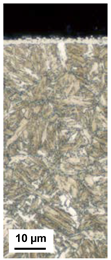
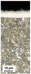
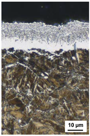
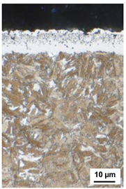
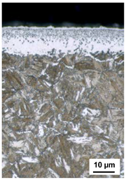
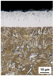
In the two-stage treatments, the process control should influence the compound layer structure in such a way that a compact compound layer with a similar thickness and composition to the reference is produced. In the first two-stage treatment, the compound layer was first built up in analogy to the procedure developed by Floe [10,11] where thin compound layers and high nitriding hardness depths can be achieved. Since in the current investigations a thick compound layer was aimed, in the first process stage a comparatively high nitriding potential of KN = 5 was chosen to form a compound layer. In analogy to the short-term treatments, a compound layer with a thickness of approximately 12 µm should already be formed in this 15 h treatment stage at 520 °C. In the second process stage, a relatively low nitriding potential was selected to limit the further growth of the compound layer and the porous layer. Table 6 shows that the compound layer is in fact similar in thickness to that obtained after the short-term treatment corresponding to the first stage. One difference, however, is the thickness of the porous zone in the compound layers. In the long-term treatment, additional pores could form in the process stage to reach the nitriding hardness depth within the long treatment period, so that the proportion of the porous zone in the compound layer is greater than desired.
Since the aim of the current investigations is a thick, compact compound layer at a high nitriding hardness depth, the sequence of the process stages was reversed in the further experiments, i.e., nitriding was first carried out at a comparatively low nitriding potential to achieve the desired nitriding hardness depth and then the compound layer was built up in a second process stage. In the first stage, it must be ensured that the nitriding potential is still sufficiently high to saturate the material with nitrogen, otherwise diffusion and thus the achievement of the nitriding hardness depth is slowed down.
Table 6 shows that reversing the sequence of the process stages led to the desired result. The layer thickness after the two treatments, which differ only in the sequence of the process stages, is similar, but as intended the proportion of porous zone has been significantly reduced by reversing the process stages.
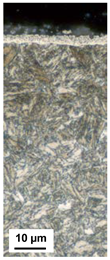
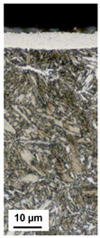
Since the targeted compound layer thickness of 15–17 µm has not yet been achieved, the parameters of the second process stage were changed in two further experiments in such a way that compound layer growth was promoted. In the third two-stage experiment, the temperature in the compound layer formation stage was increased from 520 to 550 °C, and in the last two-stage experiment, a carbon donator was added to the nitriding atmosphere, so that this was a nitrocarburizing stage. With regard to the compound layer and thickness of the porous zone, a similar result to the reference was achieved with these treatments.
Table 7 shows the phase fractions of γ’- and ε-nitride of the compound layers formed in the two-stage experiments determined by X-ray analysis. It can be stated that the phase composition of the compound layers formed by pure nitriding was approximately the same. Like the compound layer of the reference (86% γ’-nitride and 14% ε-nitride), these consisted mainly of γ’-nitride with small amounts of ε-nitride. A comparison with the 15 h short-term treatment at 520 °C with a nitriding potential of KN = 5 also shows that not only the thickness but also the phase composition of the compound layer was approximately the same after the short-term treatment and the corresponding long-term treatment.
In the two-stage treatment, in which the compound layer was formed during a nitrocarburizing stage at the end of the process, a higher proportion of ε-nitride was formed. This also corresponded approximately to the proportion of ε-nitride formed in the corresponding short-term treatment.
Therefore, from the results of the short-term treatments and the two-stage treatments it can be concluded that both the thickness of the compound layer and its phase composition in the two-stage processes were essentially determined by the process stage for compound layer formation. This opens up the possibility of influencing the compound layer formation during two-stage deep nitriding in a targeted manner.

4. Conclusions

The investigations have shown that during deep nitriding of the material 31CrMoV9 it is possible to control the nitriding layer structure through process control. In order to specifically influence the thickness and phase composition of the compound layer, a two-stage process control is suitable, in which the diffusion layer and thus the nitriding hardness depth is first adjusted in a long process stage with a comparatively low nitriding potential. Here it must be ensured that the nitriding potential is still sufficiently high enough to saturate the material with nitrogen and form a thin, closed compound layer, as otherwise diffusion is slowed down and uniformity would be negatively affected. In the second short process stage, the formation of the compound layer can be controlled by selecting the nitriding or nitrocarburizing parameters, since in such a process the thickness and phase composition of the compound layer are essentially dependent on the treatment parameters in the second process stage.
The two-stage nitriding treatments developed made it possible to produce compound layers comparable to those of the reference material 32CDV13. The question of whether a similar tooth root and flank load-bearing capacity can also be achieved with these nitrided layers is the subject of further investigations. Another subject of future investigations is the question, if the two-stage processing for a specific compound layer design is also suitable for other nitriding and tempering steels, since the current investigations are limited to the specific material 31CrMoV9.

Author Contributions

S.H.: project administration, conceptualization, investigation, methodology, writing—original draft preparation. M.S.: funding acquisition, supervision, writing—review and editing. H.-W.Z.: resources, writing—review and editing. All authors have read and agreed to the published version of the manuscript.

Funding

This IGF Project IGF 19594 N of the Forschungsvereinigung Antriebstechnike. V. is supported via AiF within the programme for promoting the Industrial Collective Research (IGF) of the German Ministry of Economic Affairs and Energy (BMWi), based on a resolution of the German Parliament. Supported by Federal Ministry of Economics and Energy by decision of the German Bundestag.

Conflicts of Interest

The authors declare no conflict of interest. The funders had no role in the design of the study, in the writing of the manuscript and in the decision to publish the results.

References

  1. Conrado, E.; Gorla, C.; Davoli, P.; Boniardi, M. A comparison of bending fatigue strength of carburized and nitrided gears for industrial applications. Eng. Fail. Anal. 2017, 78, 41–54. [Google Scholar] [CrossRef]
  2. König, J.; Hoja, S.; Tobie, T.; Hoffmann, F.; Stahl, K. In Increasing the Load Carrying Capacity of Highly Loaded Gears by Nitriding. In Proceedings of the MATEC Web of Conferences, Varna, Bulgaria, 19–22 June 2019. [Google Scholar] [CrossRef] [Green Version]
  3. Niemann, G.; Winter, H. Band 2: Getriebe allgemein, Zahnradgetriebe-Grundlagen. In Maschinenelemente; Springer: Heidelberg/Berlin, Germany, 2003. [Google Scholar]
  4. Hoja, S.; Hoffmann, F.; Zoch, H.W.; Schurer, S.; Tobie, T.; Stahl, K. Entwicklung von Prozessen zum Tiefnitrieren von Zahnrädern. HTM J. Heat Treatm. Mat. 2015, 70, 276–285. [Google Scholar] [CrossRef]
  5. Hoja, S.; Hoffmann, F.; Steinbacher, M.; Zoch, H.W. Untersuchung des Anlasseffekts beim Nitrieren. HTM J. Heat Treatm. Mat. 2018, 73, 335–343. [Google Scholar] [CrossRef]
  6. Bräutigam, F. Nitrieren im Ammoniakgasstrom: Ein Oberflächenhärte-Verfahren mit großer Zukunft. Industrie Anzeiger 1981, 103, 36–39. [Google Scholar]
  7. Limodin, N.; Verreman, Y. Fatigue strength improvement of a 4140 steel by gas nitriding: Influence of notch severity. Mater. Sci. Eng. A 2006, 435–436, 460–467. [Google Scholar] [CrossRef]
  8. Zlatanović, M.; Popović, N.; Mitrić, M. Plasma processing in carbon containing atmosphere for possible treatment of wind turbine components. Thin Solid Films 2007, 516, 228–232. [Google Scholar] [CrossRef]
  9. Wu, K.; Liu, G.Q.; Wang, L.; Xu, B.F. Research on new rapid and deep plasma nitriding techniques of AISI 420 martensitic stainless steel. Vacuum 2010, 84, 870–875. [Google Scholar] [CrossRef]
  10. Floe, C.F. A study of the nitriding process. Effect of ammonia dissociation on case depth and structure. Trans. ASM 1944, 32, 44–171. [Google Scholar]
  11. Floe, C.F. Method of Nitriding. U.S. Patent No. 2,437,249, 17 April 1946. [Google Scholar]
  12. Hassani-Gangaraj, S.M.; Moridi, A.; Guagliano, M.; Ghidini, A.; Boniardi, M. The effect of nitriding, severe shot peening and their combination on the fatigue behavior and micro-structure of a low-alloy steel. Int. J. Fatigue 2014, 62, 67–76. [Google Scholar] [CrossRef]
  13. Bossy, E.; Noyel, J.P.; Kleber, X.; Ville, F.; Sidoroffd, C.; Thibault, S. Competition between surface and subsurface rolling contact fatigue failures of nitrided parts: A Dang Van approach. Tribol. Int. 2019, 140, 105888. [Google Scholar] [CrossRef]
  14. Hoja, S.; Schurer, S.; Hoffmann, F.; Tobie, T. Tiefnitrieren von Zahnrädern. In FVA-Nr. 615 II, FVA-Forschungsheft Nr. 1147; Forschungsvereinigung Antriebstechnik e. V.: Frankfurt, Germany, 2015. [Google Scholar]
  15. Ochoa, E.A.; Wisnivesky, D.; Minea, T.; Ganciu, M.; Tauziede, C.; Chapon, P.; Alvarez, F. Microstructure and properties of the compound layer obtained by pulsed plasma nitriding in steel gears. Surf. Coat. Technol. 2009, 203, 1457–1461. [Google Scholar] [CrossRef]
  16. Zornek, B.; Hoja, S.; Tobie, T.; Hoffmann, F. Tribologische Tragfähigkeit nitrierter Innen- und Außenverzahnungen bei geringen Umfangsgeschwindigkeiten. In FVA-Forschungsheft Nr. 1206; Forschungsvereinigung Antriebstechnik e. V.: Frankfurt, Germany, 2017. [Google Scholar]
  17. Hoffmann, F.; Bujak, I.; Mayr, P.; Löffelbein, B.; Gienau, M. Verschleißwiderstand nitrierter und nitrocarburierter Stähle. HTM-Härterei-Techn. Mitt. 1997, 52, 376–386. [Google Scholar]
  18. Liedtke, D. Beitrag zum Technisch-Wirtschaftlichen Optimieren des Nitrocarburierens von Bauteilen. Ph.D. Thesis, TU Bergakademie Freiberg, Freiberg, Germany, 1986. [Google Scholar]
  19. Binder, C.; Bendo, T.; Hammes, G.; Klein, A.N.; de Mello, J.D.B. Effect of nature of nitride phases on sliding wear of plasma nitrided sintered iron. Wear 2015, 332–333, 995–1005. [Google Scholar] [CrossRef]
  20. Hollomon, J.H.; Jaffe, L.D. Ferrous Metallurgical Design; Wiley: Hoboken, NJ, USA, 1947. [Google Scholar]
  21. Huchel, U.; Klümper-Westkamp, H.; Liedtke, D. Lichtmikroskopische Bestimmung der Dicke und Porigkeit der Verbindungsschichten nitrierter und nitrocarburierter Werkstücke. In Prüfvorschrift des AWT-FA3; Arbeitsgemeinschaft Wärmebehandlung + Werkstofftechnik e. V.: Bremen, Germany, 2008. [Google Scholar]
  22. Hoffmann, R.; Mittemeijer, E.J.; Somers, M.A.J. Verbindungsschichtbildung beim Nitrieren und Nitrocarburieren. HTM-Härterei-Techn. Mitt. 1996, 51, 162–169. [Google Scholar]
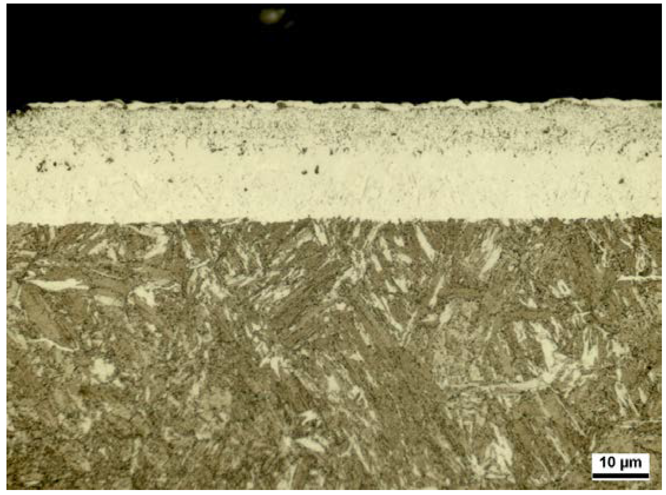
Figure 1. Compound layer of the reference state 32CDV13 deep nitrided in a two-stage treatment.
Metals 10 00455 g001
Figure 2. GD-OES nitrogen and carbon depth profiles of the deep nitrided reference state Compound layer of the deep nitrided reference state.
Metals 10 00455 g002
Figure 3. 31CrMoV9-nitrogen phase diagram calculated with Thermo-Calc.
Metals 10 00455 g003
Figure 4. Sum of GD-OES nitrogen and carbon depth profiles.
Metals 10 00455 g004
Table 1. Average compound layer thickness (CLT), thickness of the porous zone (CLTP) and nitriding hardness depth (NHD) of the toothing of the deep nitrided steel 32CDV13 in [12].
Reference 32CDV13CLTCLTPNHD
15–17 µm5–7 µmca. 1 mm
Table 2. Nitriding and nitrocarburizing treatments.
Short-Term TreatmentsLong-Term Treatments
NitridingNitrocarburizingOne-StageTwo-Stage
520 °C 15 h KN = 1520 °C 15 h KN = 1 KCB = 0.1530 °C 170 h KN=0.5520 °C 15 h KN = 5
530 °C 170 h KN = 0.5
520 °C 15 h KN = 3520 °C 15 h KN = 5 KCB = 0.1530 °C 170 h KN = 1530 °C 170 h KN = 0.5
520 °C 15 h KN = 5
520 °C 15 h KN = 5550 °C 15 h KN = 5 KCB = 0.1530 °C 170 h KN = 3530 °C 170 h KN = 0.5
550 °C 15 h KN = 5
550 °C 120 h KN = 1530 °C 170 h KN = 0.5
550 °C 15 h KN = 5 KCB = 0.1
Table 3. Compound layer thickness (CLT) and thickness of the porous zone (CLTP) after the short time nitriding and nitrocarburizing treatments.
NitridingNitrocarburizing
520 °C 15 h
KN = 1
520 °C 15 h
KN = 3
520 °C 15 h
KN = 5
520 °C 15 h
KN = 1 KCB = 0.1
520 °C 15 h
KN = 5 KCB = 0.1
550 °C 15 h
KN = 5 KCB = 0.1
Metals 10 00455 i001 Metals 10 00455 i002 Metals 10 00455 i003 Metals 10 00455 i004 Metals 10 00455 i005 Metals 10 00455 i006
CLT = 2 µmCLT = 7 µmCLT = 12 µmCLT = 3 µmCLT = 6 µmCLT = 19 µm
CLTP = 1 µmCLTP = 3 µmCLTP = 5 µmCLTP = 2 µmCLTP = 5 µmCLTP = 7 µm
Table 4. Average phase composition of the nitride layers after the short time treatments measured by X-ray diffraction.
Nitridingγ’-Nitride in %ε-Nitride in %Nitro-Carburizingγ’-Nitride in %ε-(Carbo-) Nitride in %
520 °C 15 h KN = 1ca. 74ca. 26520 °C 15 h KN = 1 KCB = 0.1ca. 54ca. 46
520 °C 15 h KN = 3ca. 79ca. 21520 °C 15 h KN = 5 KCB = 0.1ca. 23ca. 77
520 °C 15 h KN = 5ca. 89ca. 11550 °C 15 h KN = 5 KCB = 0.1ca. 68ca. 32
Table 5. Compound layer thickness (CLT), thickness of the porous zone (CLTP) and nitriding hardness depth (NHD) after the single-stage nitriding treatments.
530 °C 170 h KN = 0.5530 °C 170 h KN = 1530 °C 170 h KN = 3550 °C 120 h KN = 0.5
Metals 10 00455 i007 Metals 10 00455 i008 Metals 10 00455 i009 Metals 10 00455 i010
CLT = 6 µmCLT = 7 µmCLT = 18 µmCLT = 10 µm
CLTP = 3 µmCLTP = 4 µmCLTP = 12 µmCLTP = 6 µm
NHD = 0.75 mmNHD = 0.83 mmNHD = 0.88 mmNHD = 0.85 mm
Table 6. Compound layer thickness (CLT), thickness of the porous zone (CLTP) and nitriding hardness depth (NHD) after the two-stage nitriding treatments.
520 °C 15 h KN = 5
530 °C 170 h KN = 0.5
520 °C 15 h KN = 5
530 °C 170 h KN = 0.5
550 °C 15 h KN = 5
530 °C 170 h KN = 0.5
550 °C 15 h KN = 5
KCB = 0.1
Metals 10 00455 i011 Metals 10 00455 i012 Metals 10 00455 i013 Metals 10 00455 i014
CLT = 12 µmCLT = 13 µmCLT = 17 µmCLT = 20 µm
CLTP = 7 µmCLTP = 6 µmCLTP = 8 µmCLTP = 8 µm
NHD = 0.75 mmNHD = 0.82 mmNHD = 0.81 mmNHD = 0.85 mm
Table 7. Average phase composition of the nitride layers after the two-stage long time treatments measured by X-ray diffraction.
Two-Stage Nitridingγ’-Nitride in %ε-Nitride in %
520 °C 15 h KN = 5
530 °C 170 h KN = 0.5
ca. 88ca. 12
530 °C 170 h KN = 0.5
520 °C 15 h KN = 5
ca. 85ca. 15
530 °C 170 h KN = 0.5
550 °C 15 h KN = 5
ca. 88ca. 12
530 °C 170 h KN = 0.5
550 °C 15 h KN = 5 KCB = 0.1
ca. 60ca. 40