Article

Influences of a Hot-Working Process on the Microstructural Evolution and Creep Performance of a Spray-Formed Nickel-Based Superalloy

1
Institute of Powder Metallurgy and Advanced Ceramics, School of Materials Science and Engineering, University of Science and Technology Beijing (USTB), Beijing 100083, China
2
Academy for Advanced Interdisciplinary Studies and Department of Mechanical and Energy Engineering, Southern University of Science and Technology (SUSTech), Shenzhen 518055, China
3
Science and Technology on Advanced High Temperature Structural Materials Laboratory, Aero Engine Corporation of China Beijing Institute of Aeronautical Materials (BIAM), Beijing 100095, China
*
Authors to whom correspondence should be addressed.
Metals 2020, 10(4), 454; https://doi.org/10.3390/met10040454
Submission received: 8 February 2020 / Revised: 17 March 2020 / Accepted: 23 March 2020 / Published: 31 March 2020

Abstract

:
A new third generation nickel-based powder metallurgy (PM) superalloy, designated as FGH100L, was prepared by spray forming. The effects of hot isostatic pressing (HIP) and isothermal forging (IF) processes on the creep performance, microstructure, fracture, and creep deformation mechanism of the alloy were studied. The microstructure and fracture were characterized by optical microscopy (OM), scanning electron microscopy (SEM), and transmission electron microscopy (TEM). The coupled HIP and IF process improved the creep performance of the alloy under the creep condition of 705 °C/897 MPa. As for both the HIPed and IFed alloys, the creep process was dominated by the accumulation of dislocations and stacking faults, cutting through γ′ precipitates. The microstructural evolution was the main factor affecting the creep performance, which mainly manifested as coarsening, splitting, and morphology change of γ′ precipitates. Both the creep fractures of the HIPed and IFed alloys indicated intergranular fracture characteristics. In the former, wedge-shaped cracks usually initiated at the trigeminal intersection of the grain boundaries, while in the latter, cavity cracks generate more easily around the serrated curved grain boundary and carbides.

Graphical Abstract

1. Introduction

The nickel-based powder metallurgy (PM) superalloys are of the most important materials for manufacturing turbine disks of advanced aeroengines. The failure of most load-bearing components under the condition of high temperature and high pressure is caused by high-temperature creep [1], which can lead to excessive plastic deformation or creep fracture of aeroengine parts. There has been a lot of research work on the creep deformation mechanisms of nickel-based superalloys. The turbine disk of aeroengine can work continuously for hundreds to thousands of hours at 650–750 °C during its service. It is predicted that the service temperature requirements of the high-pressure compressor and turbine disk of an aeroengine may rise to over 750–800 °C in the future. Therefore, it is necessary to develop high temperature materials that can withstand higher temperature and have better creep and oxidation resistance. Accordingly, it is necessary to continuously improve the preparation process of the alloy. At present, there are three kinds of preparation processes of superalloys for turbine disk. The first one is the traditional casting and forging (C & W) process. For example, the superalloys such as Inconel718, U720Li, and AD730TM, which have service temperature of 650–700 °C, are produced by the C & W process [2]. The second one is made by the powder metallurgy (PM) process, that is, vacuum induction melting + argon atomization powder making + electrostatic powder screening and then canning + compacting (hot pressing, hot isostatic pressing, extrusion) + the hot working deformation (isothermal forging, die forging) process. For example, the superalloys, such as René88DT, RR1000, René104 (ME3), Alloy10, LSHR, NR3, and NR6 [3,4,5], are produced by the PM process. Russia has developed the fifth generation of BBП system (BB750П, BB751П, BB752П, BB753П) PM superalloys [6], and the PM superalloy disks are manufactured by the process of plasma rotation electrode process (PREP) for superalloy powders + direct hot isostatic pressing (As-HIP). FGH4095, FGH4096, FGH4097, FGH4098, and other powder superalloys [4,7,8,9,10] developed in China adopt the process of powder metallurgy, and the working temperature ranges from 650 to 750 °C. The third one is spray forming + compaction (hot isostatic pressing, extrusion) + the isothermal forging process. Compared with C & W or PM technology, the processing steps of spray forming technology [11] from atomization to final pre-forming are significantly reduced, which not only saves the remelting and transformation steps in the process of C & W processing but also avoids the segregation of alloy elements in the solidification process, as well as the screening, electrostatic precipitation, canning, and degassing steps of powder in PM processing. Therefore, spray forming technology has become a cost-effective and efficient preparation method. In this paper, two processes were employed to prepare a new third generation nickel-based PM superalloy FGH100L, i.e., spray forming + HIP and spray forming + HIP + IF. The FGH100L alloy is developed based on the composition of the LSHR alloy [5], and its designed working temperature is above 700 °C.
The microstructure and creep mechanism of various single crystal and polycrystalline superalloys have been widely studied. The main creep control parameters of single crystal superalloy are orientation, porosity, and the characteristics of strengthening precipitates. The studies on the creep behavior of polycrystalline superalloys mainly focus on the characteristics of grain and γ′ precipitates, the role of trace elements, and dislocation microstructure. Zhu et al. [12] proposed a physical model of the creep deformation of nickel-based single crystal superalloys, which is sensitive to the chemical composition and microstructure. Zhang et al. [13] studied the creep properties of the alloy M4706 at 900 °C. When the applied stress was increased from 300 to 375 MPa, the steady-state creep rate gradually increased, while the creep fracture life decreased. Li et al. [14] studied the effect of orientation on the creep behavior of the third-generation nickel-based single crystal superalloy at 850 °C. Zhao et al. [15] studied the deformation and damage characteristics of the 4.5%Re/3.0%Ru nickel-based single crystal superalloy during creep. Song et al. [16] studied the influence of Ru on the microstructure and creep properties of the two alloys. With the increasing amount of Ru, the creep fracture life of the alloy increased significantly. Wu et al. [17] studied the microstructural evolution and creep behavior of an Ni3Al-based as-cast superalloy under a high-temperature heat treatment. Yue et al. [18] studied the high-temperature creep behavior of the third-generation nickel-based single crystal superalloy under the condition of 1100 °C/120–174 MPa. Huo et al. [19] studied the microstructure of the alloys with different contents of Co (7.0 wt % and 15.0 wt %), Cr (3.5 wt % and 6.0 wt %), Mo (1.0 wt % and 2.5 wt %), and Ru (2.5 wt % and 4.0 wt %) under the creep condition of 950 °C/400 MPa. Tian et al. [20] studied the effect of element Re on the internal deformation mechanism of phase in nickel-based single crystal superalloy during high-temperature creep. Lv et al. [21] studied the superdislocation structure of nickel-based single crystal superalloy at the <100> interface after creeping for 85 h at 1100 °C/130 MPa. Mohammad et al. [22] studied the high-temperature creep behavior of Inconel-713C, a nickel-based superalloy used for turbine blades. Wollgramm et al. [23] studied the creep behavior of nickel-based single-crystal superalloy, mainly considering the effects of stress and temperature on the minimum creep rate. Viswanathan et al. [24] studied the substructures of the superalloy René 88DT after creep deformation under two stress levels at 650 °C with small strain (0.5%). They found that microtwinning was the main deformation mode under low stress. At higher stress, a dislocation of 1/2<110> passed through the matrix and the tertiary γ′ precipitate, and a dislocation loop surrounded the larger secondary γ′ precipitate. Xie et al. [7] studied the roles of dislocation morphology, creep behavior, and dislocation network during the creeping of the FGH95 superalloy through a creep test, microstructure observation, and comparative analysis. Peng et al. [8] studied the creep properties of the FGH96 superalloys after different aging treatments under the creep condition of 700 °C/690 MPa and found that the creep life decreased with the increase in the volume fraction of tertiary γ′ precipitate. Jia et al. [25,26] studied the effects of solid solution treatment and cooling rate on the microstructure and creep properties of the PM superalloy FGH100L at 705 °C/897 MPa.
Hot isostatic pressing (HIP) is a kind of manufacturing technology that applies high temperature and high pressure to materials at the same time, making materials produce diffusion connection or densification, and it is gradually used for forming complex parts with integral structure. Isothermal forging (IF) is a kind of advanced hot working technology, which heats the mold to the same temperature as the forging billet, and forms the precision forgings with complex shapes with lower deformation rate and fewer fire times under constant temperature.
In this paper, the microstructure and creep properties of the alloys prepared by these two different processes were comparatively studied. Based on the analysis of the fracture characteristics, microstructure, and dislocation configuration of the alloy after creep testing, the creep deformation and fracture mechanisms of the alloy were discussed. It is expected to provide a basis for life prediction and the safe use of the new PM superalloy for turbine disks.

2. Materials and Methods

The FGH100L master alloy was prepared by a double melting process, i.e., vacuum induction melting plus vacuum consumable remelting (VIM + VAR). The main chemical composition of the FGH100L alloy ingot is (mass fraction, wt%): C 0.04, Cr 12.24, Co 20.90, Mo 2.77, W 4.4, Al 3.48, Ti 3.35, Nb 1.52, Ta 1.47, B 0.023, Zr 0.04, and Ni bal.
The FGH100L alloy ingot (diameter: 200 mm, height: 300 mm) was deposited by spray forming. High purity N2 was used as an atomizing gas. The hot isostatic pressing (HIP) was then carried out upon the ingot without canning: the ingot was heated to 1160 °C at a rate of 10 °C/min, and then held at 150 MPa for 3 h in order to achieve high degree densification. The isothermal forging (IF) experiment was carried out: the forging temperature was 1150 °C, the pressing rate was 0.1mm/s, and the engineering deformation was about 30.4%. The samples, taken from the alloy ingots produced by these two different processes, were then subject to solid solution treatment followed by two-stage aging, i.e., 1130 °C/1 h/fan quenching + 850 °C/4 h/air cooling (AC) + 775 °C/8 h/AC. In the rest of the article, the alloy prepared only by the HIP process was designated as the “HIPed alloy” for convenience, while the alloy prepared by the combined HIP and IF process was designated as the “IFed alloy”.
The creep tests were carried out on the samples according to China’s national standard GB/T 2039-2012 “Metallic materials—Uniaxial creep testing method in tension” [27]. The test equipment was CSS type creep test machine of Changchun testing machine factory (Changchun, China). The Ф5 mm round non-standard creep sample was used, whose specific dimension was shown in Figure 1. The creep temperature range of 650–750 °C and stress range of 450–897 MPa were selected. Under different temperature and stress conditions, 2–3 samples were taken for creep performance testing. The grain morphology was observed under a metallographic optical microscope XTX-200 (Jiangnan Optical Instrument Factory, Nanjing, China) and the sample etching solution was 10 g CuCl2 + 50 mL HCl + 50 mL H2O. The ImageJ software was used to calculate the size of precipitates (at least 100 data were collected to calculate the average value). The characteristics of γ′ precipitate and grain boundary distribution were observed by JSM-6701F (JEOL Japan Electronics Co., Ltd., Tokyo, Japan) and ZEISS EVO®18 scanning electron microscopy (SEM) (Carl Zeiss AG Co., Ltd., Oberkochen, Germany). The electrolytic polishing solution was 20 vol% H2SO4 + 80 vol% CH3OH, and the electrolytic etching solution was 9 g CrO3 + 90 mL H3PO4 + 30 mL C2H5OH. The dislocations and carbides in the alloy after creep fracture were analyzed using a transmission electron microscope (TEM) and energy dispersive spectrometer (EDS). The TEM samples were cut at the section 5 mm below the creep fracture surface first and then the specimens were mechanically ground and polished to thin slices with a diameter of 3 mm. Then, twin-jet electropolishing was done using a solution of 10% HClO4 + 90% C2H5OH at −30 °C. The FEI Tecnai G2 F20 field emission gun TEM (FEI Co., Ltd., Hillsboro, OR, USA) was used to observe the samples with an operating voltage of 200 kV.

3. Results

3.1. Creep Properties and Creep Characteristics

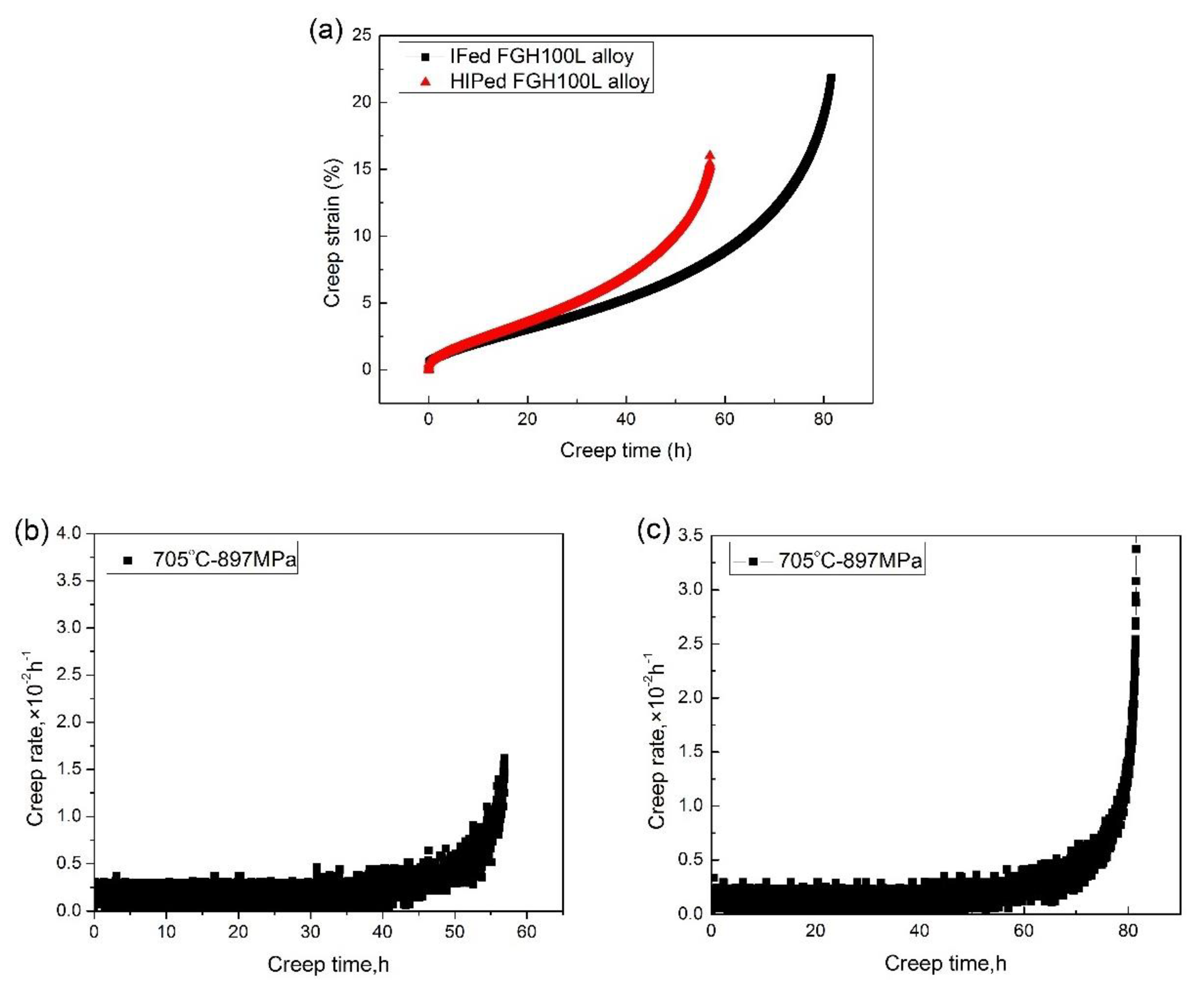
Generally, the creep curve can be divided into three stages: the primary creep stage, the secondary stage of steady-state creep, and the tertiary stage of accelerated creep. Figure 2 shows the creep curves of the HIPed and IFed alloys at 705 °C/897 MPa. No distinct primary creep stage can be observed in the creep curves, and the secondary and tertiary stages predominate in these curves. According to Figure 2a, under the same creep test conditions, the creep fracture time and strain of the IFed alloy are increased by about 24.6 h and 5.8%, respectively, compared with that of the HIPed alloy. Figure 2b shows that the minimum creep speed of the HIPed alloy is 0.1449 × 10⁻² h−1, while the IFed alloy has a smaller steady-state creep rate of 0.1199 × 10⁻² h−1 in Figure 2c. Table 1 shows the comparison of specific parameter values. In general, the primary creep behaviors of these two alloys are similar: it is very short and the creep rate decreases with increasing time. During the secondary stage of creep, the creep rate basically remains unchanged with the increase in time, which is the lowest in the whole creep process due to the balance between work hardening and recovery softening. During the steady-state creep stage, the creep rate of the IFed alloy is lower than that of the HIPed alloy, and the creep time of the former is about 20 h longer than that of the latter. In the tertiary creep stage, the creep rate increases with time, and finally fracture occurs. The increase in creep rate is not only related to the increase in stress, but also to the evolution of the microstructure and the formation and growth of cracks.
The stress-rupture properties of the FGH100L alloys under different processes are compared. Table 2 shows that under the condition of 705 °C/897 MPa, the average stress-rupture life of the IFed alloy is 1.4 times longer than that of the HIPed alloy, and the elongation after fracture increases by 2%. The results show that under the same test condition, different processes have obvious effects on the creep and rupture properties of the alloys, which may be related to the different microstructures of the alloys under different processing conditions.

3.2. Creep Microstructure Characteristics

Table 3 shows the density and relative density of the FGH100L alloys under these two processes, which are measured by the drainage method [28]. According to Table 3, the relative densities of the HIPed and IFed alloys are 98.44% and 99.16%, respectively. Through the HIP treatment, the porosities in the as-sprayed preforms can be closed and the densities can be increased. The HIP temperature is the key factor affecting the effect of porosities. Too high a temperature can easily cause the complete dissolution of the large γ′ precipitates at the grain boundary, reduce the resistance of grain boundary migration, increase the recrystallization area, and lead to the gradual phagocytosis and growth of the grains. Too low a temperature is not conducive to the full diffusion of solute atoms around the porosities, so that the porosities cannot be completely closed and full densification cannot be achieved. In this paper, the HIP temperature is 1160 °C, which is close to 1170 °C, at which the γ′ precipitates in the FGH100L alloy is completely dissolved. At the same time, the densification effect of the alloy is obvious under a pressure of 150 MPa. The IF temperature is 1150 °C, and the deformation amount is 30.4%. Relatively large plastic deformation occurs in the alloy, the storage energy of alloy deformation is sufficient, and the dynamic recrystallization occurs to refine the grain. In addition, the IF can also break the prior particle boundary (PPB) and carbide, and close the internal microscopic porosities of the alloy. Therefore, the number of microscopic porosities in the IFed alloy was further reduced, and the densification effect was better than that in the HIPed alloy.
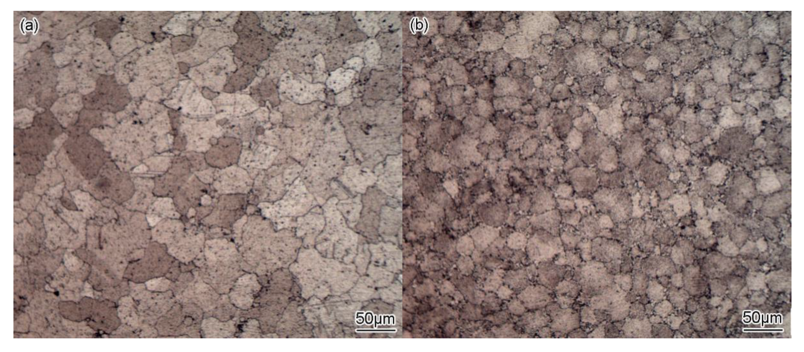
Figure 3 shows the initial morphology of grains and γ′ precipitates in both of HIPed and IFed alloys before creep. It can be seen from Figure 3a that there are a few recrystallized grains in the HIPed alloy. The grains are generally polygonal and the grain boundaries tend to be flat. The grain size in the HIPed alloy ranges from 12 to 120.49 μm, and the average grain size is 40.73 μm. Figure 3b shows that a large number of fine recrystallized grains can be found in the IFed alloy, and the average size is 4.33 μm. The larger grain size ranges from 4.96 to 53.99 μm, with an average grain size of 24.25 μm. Dynamic recrystallization occurs during the IF process, which can refine grains and form curved grain boundaries, and the morphology of grains changes from polygon to nearly spherical.
Figure 3c,e show the γ′ morphology in the HIPed alloy. The average size of the primary γ′ precipitates is 1.98 μm in Figure 3c. These primary γ′ precipitates are in irregular strip or sheet shapes and are mainly distributed on the grain boundaries. Figure 3e shows that a large number of secondary γ′ precipitates are dispersed in the grains, with an average size of 0.84 μm. During the splitting process, the secondary γ′ precipitates mainly split into triangular or cubic shapes, due to the interaction between the adjacent γ′ precipitates. The tertiary γ′ precipitates are formed during the aging process and act as supplementary strengthening. The big tertiary γ′ precipitates (B-tertiary γ′) are mainly distributed in the grains and appear in spherical or cubic shapes with a size of less than 0.14 μm. The small tertiary γ′ precipitates (S-tertiary γ′) are distributed in the phase boundary between the primary and secondary γ′ precipitates and the matrix, with a size of about 0.06 μm and a fine spherical shape (see in the amplified area in Figure 3e). The morphology of γ′ precipitate is determined by the interface and elastic strain energy. The change in the supersaturation of alloying elements in the matrix caused by the decrease in temperature is the main factor controlling the nucleation of γ′ precipitate, while the diffusion of alloying elements in the matrix is the main factor controlling the growth of γ′ precipitate [10].
Figure 3d,f show the γ′ morphology in the IFed alloy. In Figure 3d, there are a small number of incomplete re-dissolved primary γ′ precipitates distributed in the grain boundary, with an average size of 1.75 μm in irregular strip or sheet shapes. In Figure 3f, a large number of cubic secondary γ′ precipitates are distributed in the grains with an average size of 0.52 μm. There are also two sizes of tertiary γ′ precipitates in the IFed alloy. The big tertiary γ′ precipitates are mainly distributed in the grains and appear in spherical and cubic shapes with an average size of 0.08 μm. The small tertiary γ′ precipitates are of fine spherical shape with a size of about 0.01 μm and are distributed in the phase boundary between the primary and secondary γ′ precipitates and the matrix.
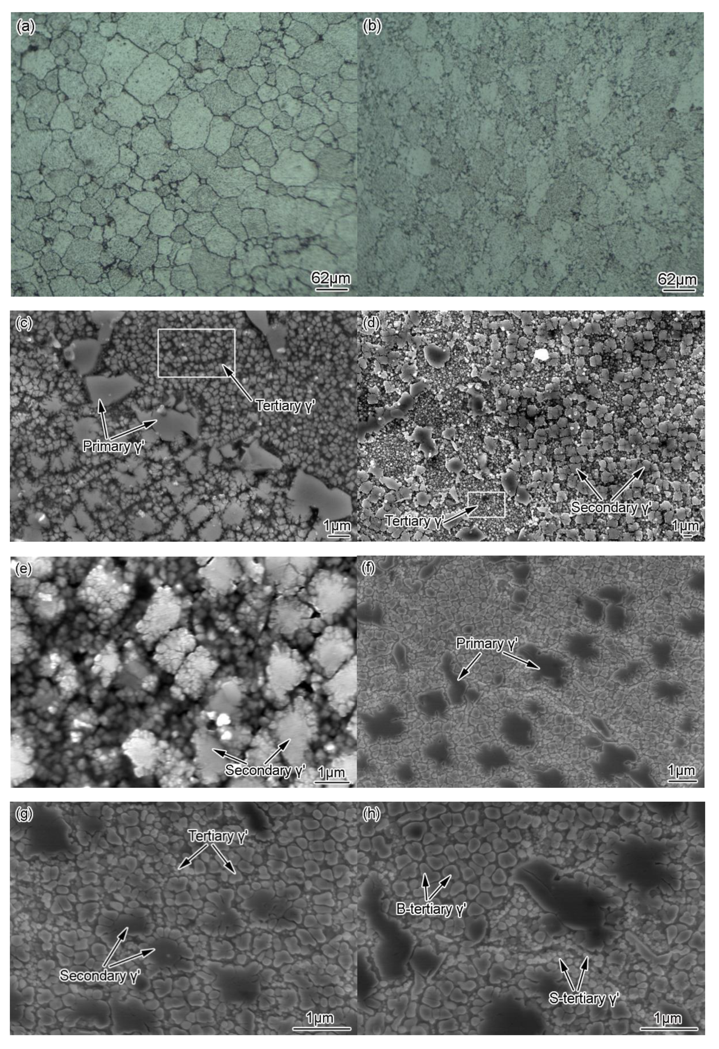
Figure 4 shows the morphology of grains and γ′ precipitates in both of HIPed and IFed alloys after creep at 705 °C/897 MPa. The samples were taken around the fracture surface along the longitudinal direction (parallel to the stress direction). The ImageJ software was used to calculate the size of the precipitates in two different process state alloys. Figure 4a shows that the grain size ranges from 15.22 to 133.13 μm in the HIPed alloy after creep, and the average grain size is 54.44 μm. The recrystallized grains in the HIPed alloy after creep are larger and more evenly distributed than those before creep. Figure 4b shows that a large number of fine recrystallized grains can still be seen in the IFed alloy after creep. The smaller recrystallized grains range from 2.64 to 15.78 μm after creep, and the average grain size is 8.31 μm, which is slightly larger than that of recrystallized grains before creep. The larger grains range from 7.24 to 107.63 μm, and the average grain size is 37.24 μm. Table 4 shows the statistics of average grain size and γ′ precipitate size before and after creep of FGH100L alloy in different processes. According to Table 4, the grain size and γ′ precipitate size of both the HIPed and IFed alloys tend to increase after creep.
It can be seen from Figure 4c that after creep, part of primary γ′ precipitates coarsened in the HIPed alloy, with an average size of 2.32 μm, distributing on the grain boundaries. In Figure 4d,e, some secondary γ′ precipitates are coarsened to form a raft structure. These secondary γ′ precipitates, with an average size of 1.18 μm, are mainly distributed in the crystal with cubic shapes. Compared with that before creep, there is only one size of cubic tertiary γ′ precipitates in the alloy after creep. These tertiary γ′ precipitates, with an average size of 0.23 μm, are mainly distributed in the phase boundary between the primary and secondary γ′ precipitates and the matrix. The phenomenon of the coarsening and growing of tertiary γ′ precipitates is obvious. A large number of tertiary γ′ precipitates tend to gather in a separate wide region, as indicated by the arrows in Figure 4c,d. Compared with the microstructure in Figure 3c,e, it is found that, in the microstructure after creep, the γ′ precipitates grow along a preferred direction under the action of stress and temperature. This coarsening behavior directly affects the creep fatigue life of the alloy, and the creep fracture usually occurs along the coarsening direction.
Figure 4f–h shows the morphology of γ′ precipitates in the IFed alloy after creep. Compared with the HIPed alloy, the IFed alloy has smaller sized γ′ precipitates after creep, as shown in Figure 4f and Table 4. Compared with Figure 3d,f, the γ′ precipitate morphology in the IFed alloy changed after creep. The size of the primary γ′ precipitate does not change significantly, and the average size is 1.72 μm. These primary γ′ precipitates are distributed on the grain boundaries with an irregular long strip shape. The average size of the secondary γ′ precipitate is 0.62 μm. As shown in Figure 4g, these secondary γ′ precipitates are mainly in a cubic shape and distributed in the crystal, but no raft structure is observed. The size of the tertiary γ′ precipitate is significantly larger than that before creep, and there are two different sizes of tertiary γ′ precipitates, as shown in Figure 4h. The division and coarsening of the big tertiary γ′ precipitates, with an average size of 0.24 μm, occur simultaneously. Part of these big tertiary γ′ precipitates coarsen to form raft structures in a cubic shape. These big tertiary γ′ precipitates are mainly distributed within the grain. The small tertiary γ′ precipitates, in a spherical shape and with an average size of 0.06 μm, tend to coarsen. These small tertiary γ′ precipitates are distributed in the phase boundary between the primary and secondary γ′ precipitates and the matrix.
According to the literature [29,30,31], after the creep of the general nickel-based superalloy, the γ′ precipitates in the alloy will directionally coarsen to form raft structures, which corresponds to the first stage of macroscopic alloy creep. The directional coarsening of γ′ precipitate is a spontaneous process of energy reduction, so it is beneficial to the increase of creep strength. During the second stage of steady-state creep, the raft structure is basically unchanged, but the dislocation network at the interface will undergo a process from formation to gradual dissipation. In the third stage of creep, the raft structure will coarsen violently. At this time, some holes will form and gradually expand at pores and phase interfaces, which will eventually lead to material fracture.

3.3. Creep Fracture Characteristics

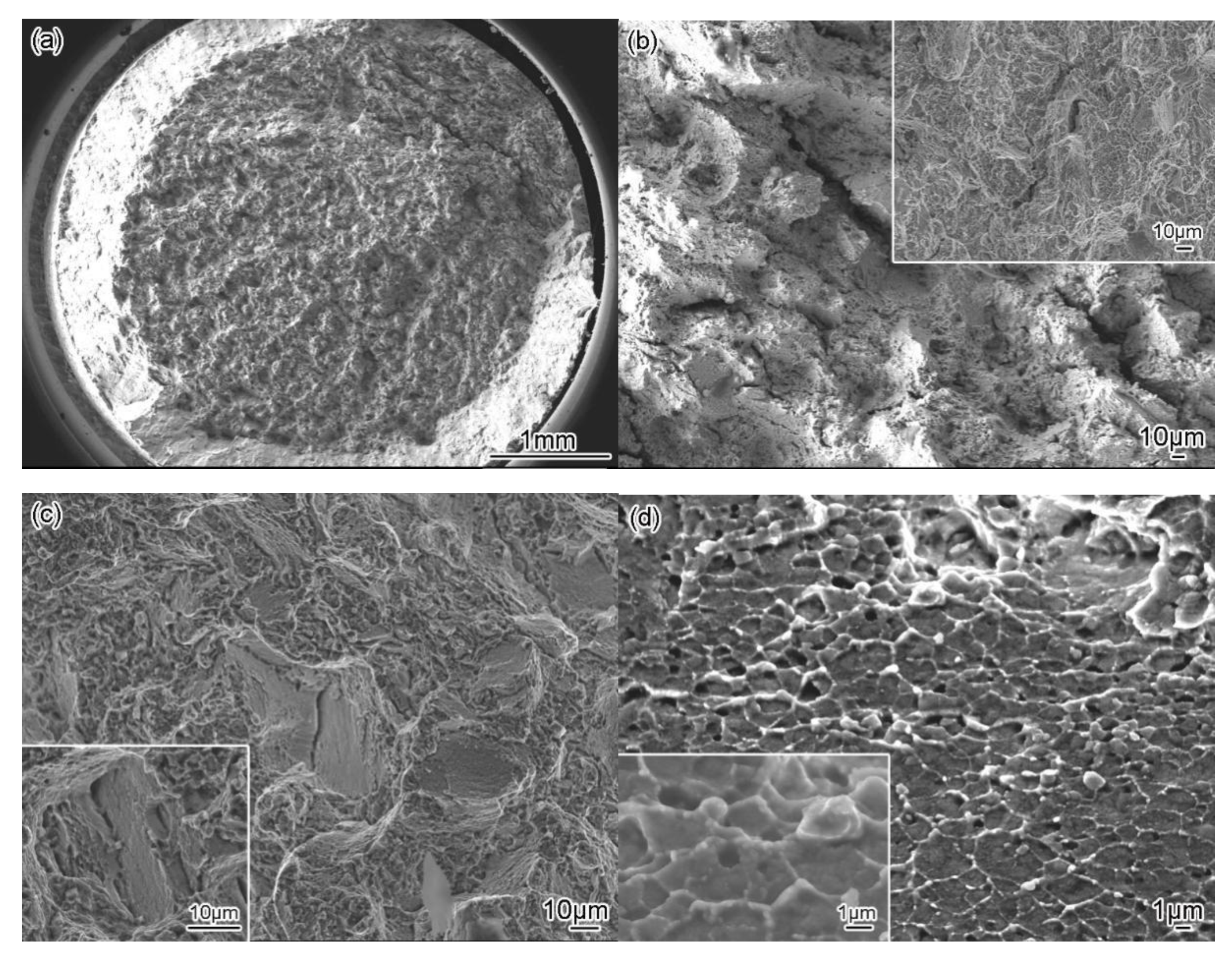
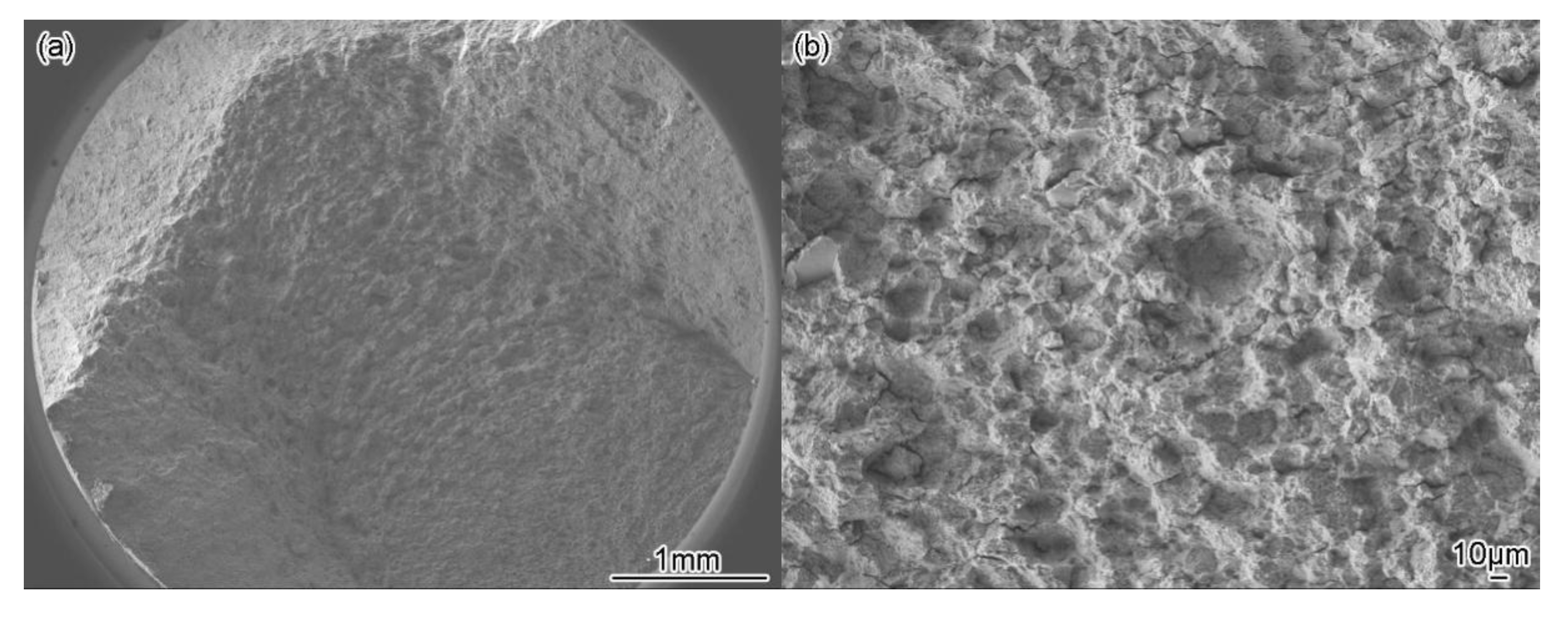
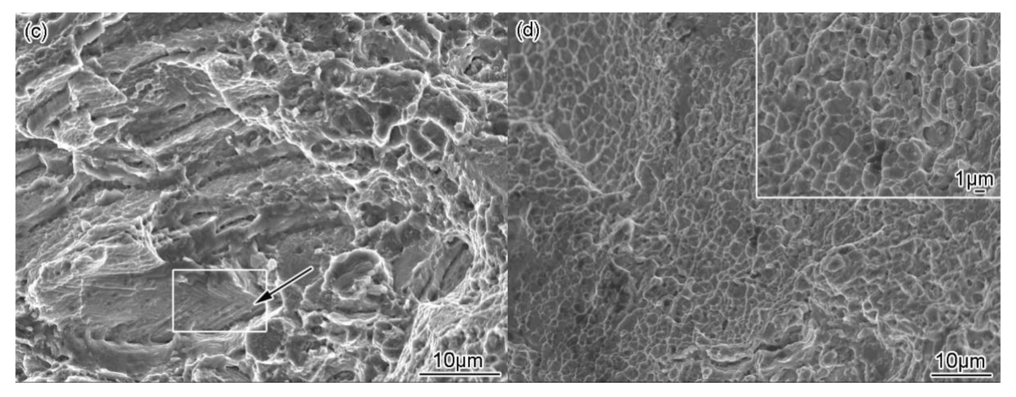
Figure 5 and Figure 6 show the creep fracture morphology of the FGH100L alloy. The creep fracture life of the HIPed and IFed alloys is 56.96 h and 81.54 h, respectively. It can be seen clearly from Figure 5a and Figure 6a that there are three characteristic regions of creep fracture in both of the alloys, namely, the fracture source region, the propagation region, and the final fracture region (i.e., the shear lip region). Overall, the fracture surfaces are rough and uneven. The shear lip region of the creep fracture in the IFed alloy (Figure 6a) is larger than that in the HIPed alloy (Figure 5a), indicating that the IFed alloy has better plasticity.
Figure 5b demonstrates intergranular fracture characteristics in the fracture source region of the HIPed alloy. Since the grain boundary is the origin of the crack, most of the creep cavities are generated in the grain boundary perpendicular to the tensile stress. Moreover, under the higher stress load, the cracks are initiated at the trigeminal intersection of the grain boundaries, which are shown as wedge-shaped cracks (see the amplified area in Figure 5b). With the increase in stress, the wedge-shaped cracks widen. Figure 5c shows small platforms, deep dimples, and secondary cracks in the propagation region. Figure 5d shows shallow dimples in the shear lip region.
Figure 6b shows the fracture source region of the IFed alloy, indicating the feature of intergranular fracture and the hole-type cracks. In Figure 6c, there are deep dimples, secondary cracks, and small steps with deep interlaced slip traces in the propagation region (see the area indicated by the arrow in the figure). In Figure 6d, the deep dimples (as shown in the magnified area in the figure) can be seen in the shear lip region.
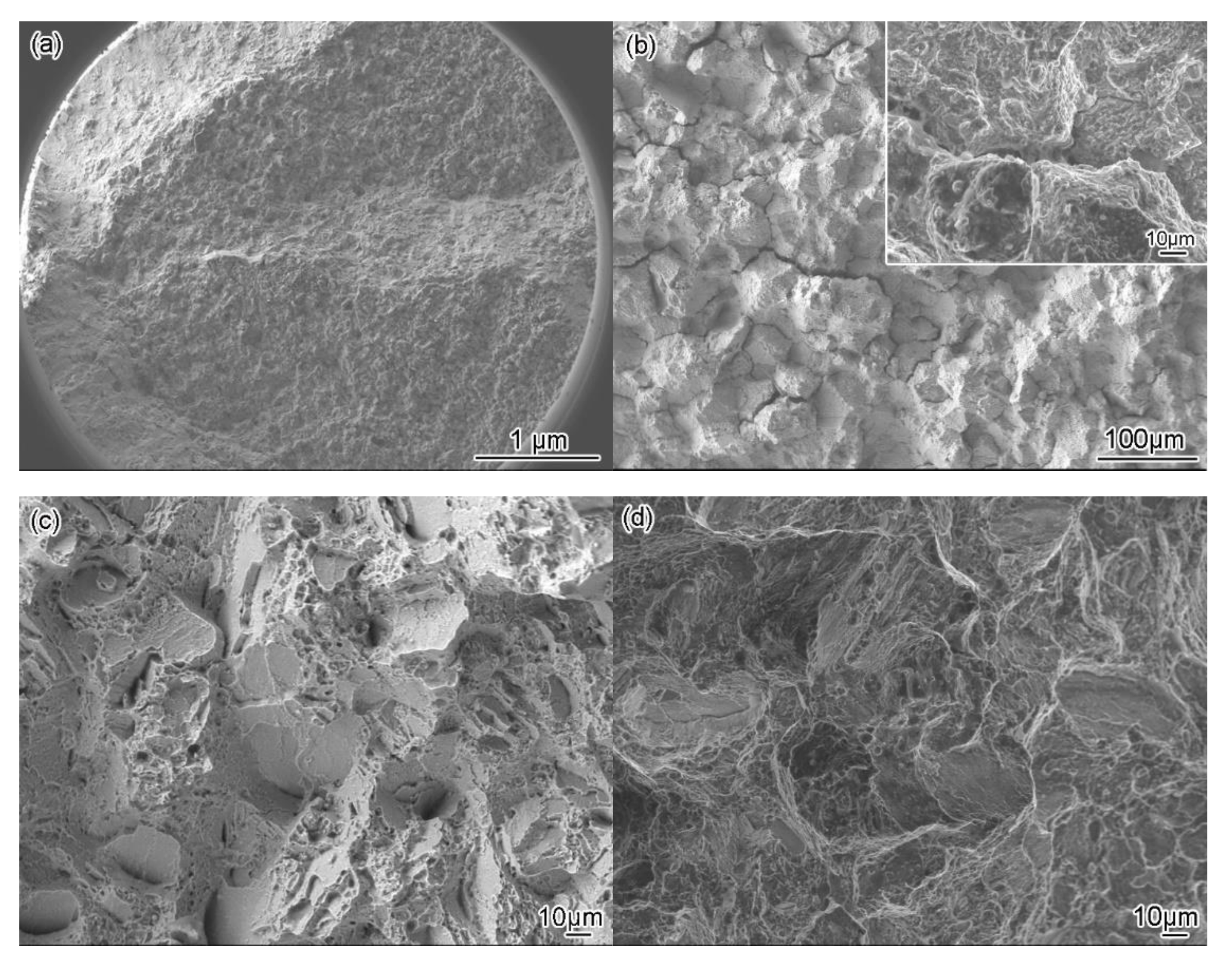
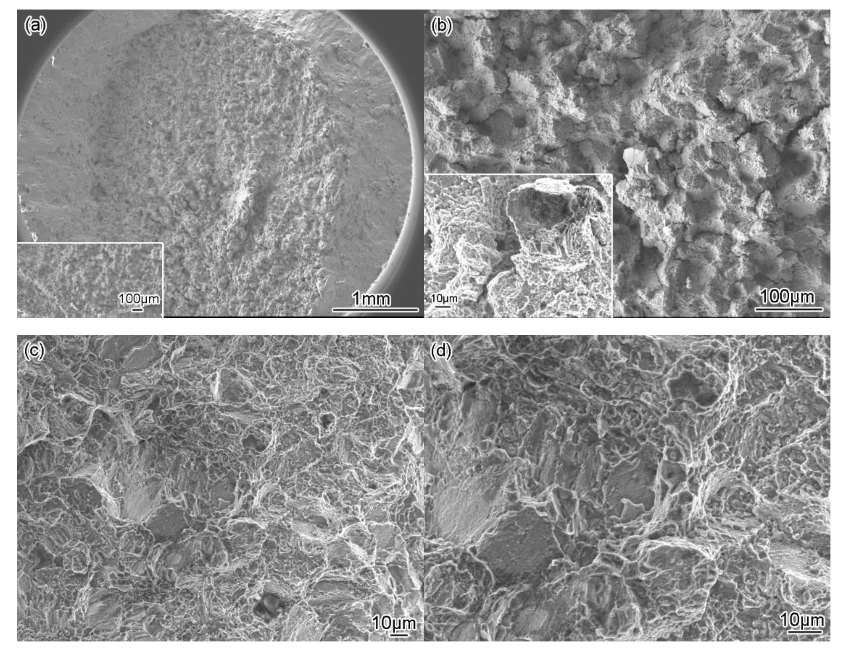
Figure 7 and Figure 8 show the fracture morphology of the stress-rupture samples of the HIPed and IFed alloys, and the endurance life of these two alloys is 47.8 h and 66.5 h, respectively. According to Figure 7a and Figure 8a, the fracture surfaces of the two samples are rough and uneven like a sponge as a whole, and the fracture includes the fracture source region, propagation region and final fracture region (i.e., shear lip region).
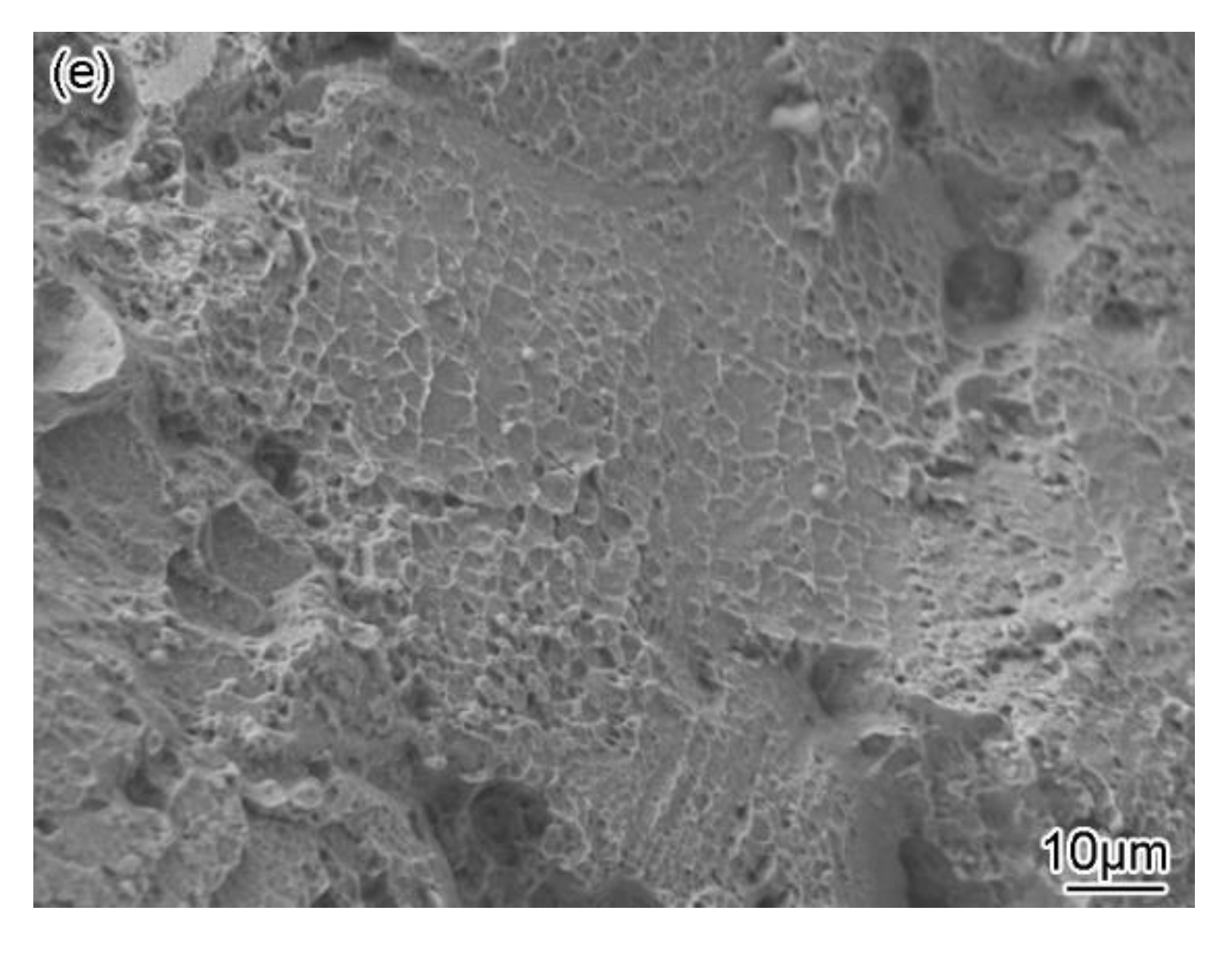
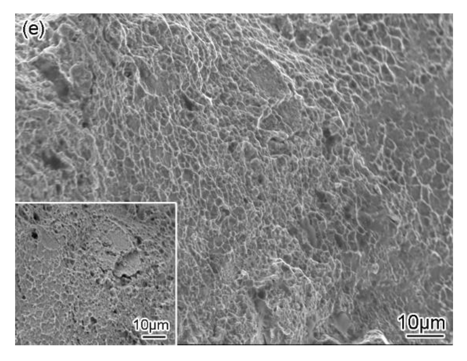
In Figure 7b, intergranular fracture morphology and long wedge-shaped cracks can be seen in the fracture source region of the HIPed alloy (in the amplified region at the upper right corner in the figure). In Figure 7c,d, small planes, tearing edges, steps, and deep dimples can be seen in the propagation region. Figure 7e shows that there are shallow dimples in the shear lip region.
In Figure 8b, intergranular fracture features are demonstrated in the fracture source region of the IFed alloy and cavity cracks can be found (as shown in the amplified area at the lower left corner in the figure). This is because the IFed alloy has serrated, curved grain boundaries, so the cavity cracks are easier to germinate and expand at the grain boundary and carbide interface. Figure 8c,d show the features of small planes, tearing edges, and deep dimples in the propagation region. Figure 8e shows deep dimples in the shear lip region. The above analyses show that the rupture fractures of both HIPed and IFed alloys are intergranular fractures under the stress-rupture condition of 705 °C/897 MPa.

4. Discussion

4.1. Dislocation Configuration and Creep Deformation Mechanism

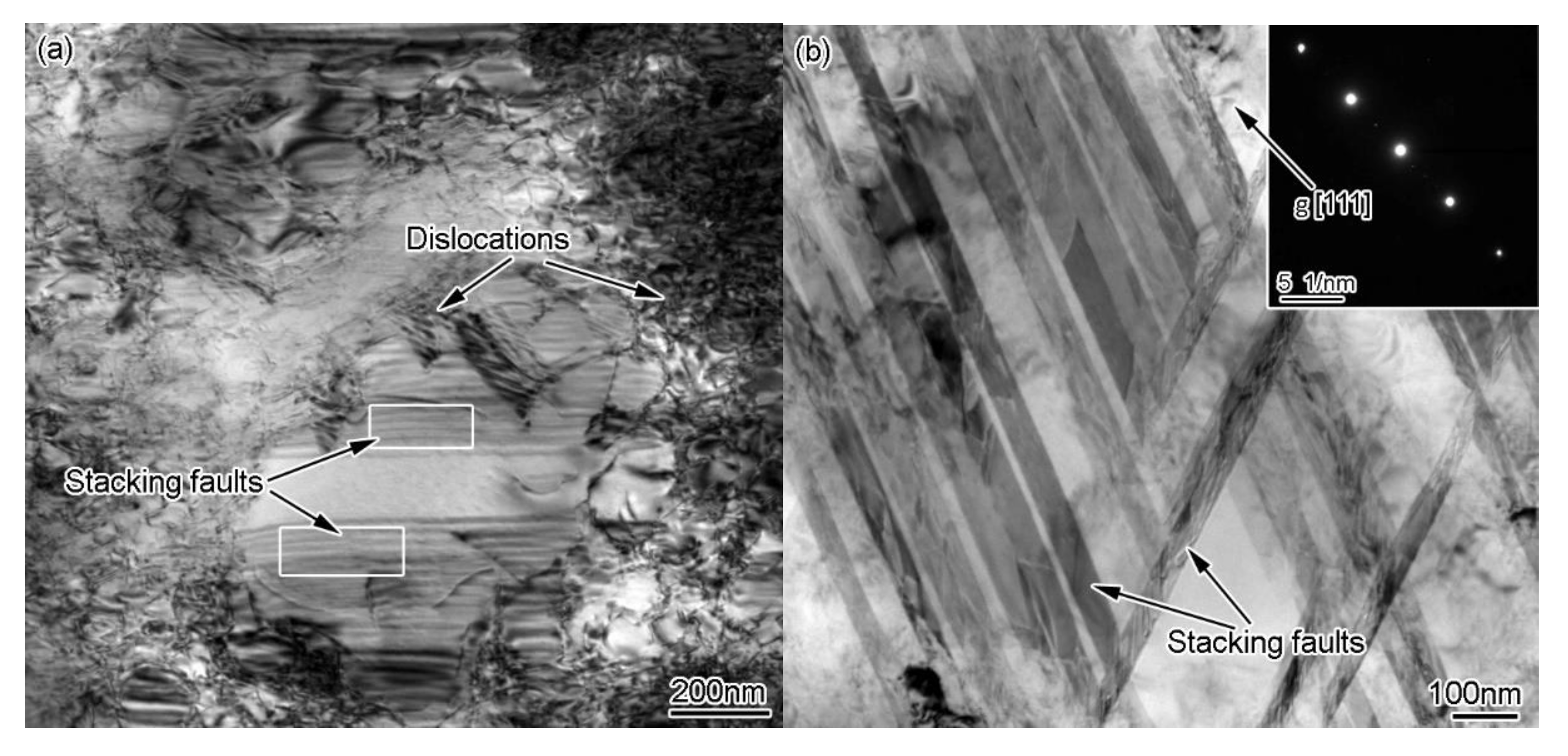
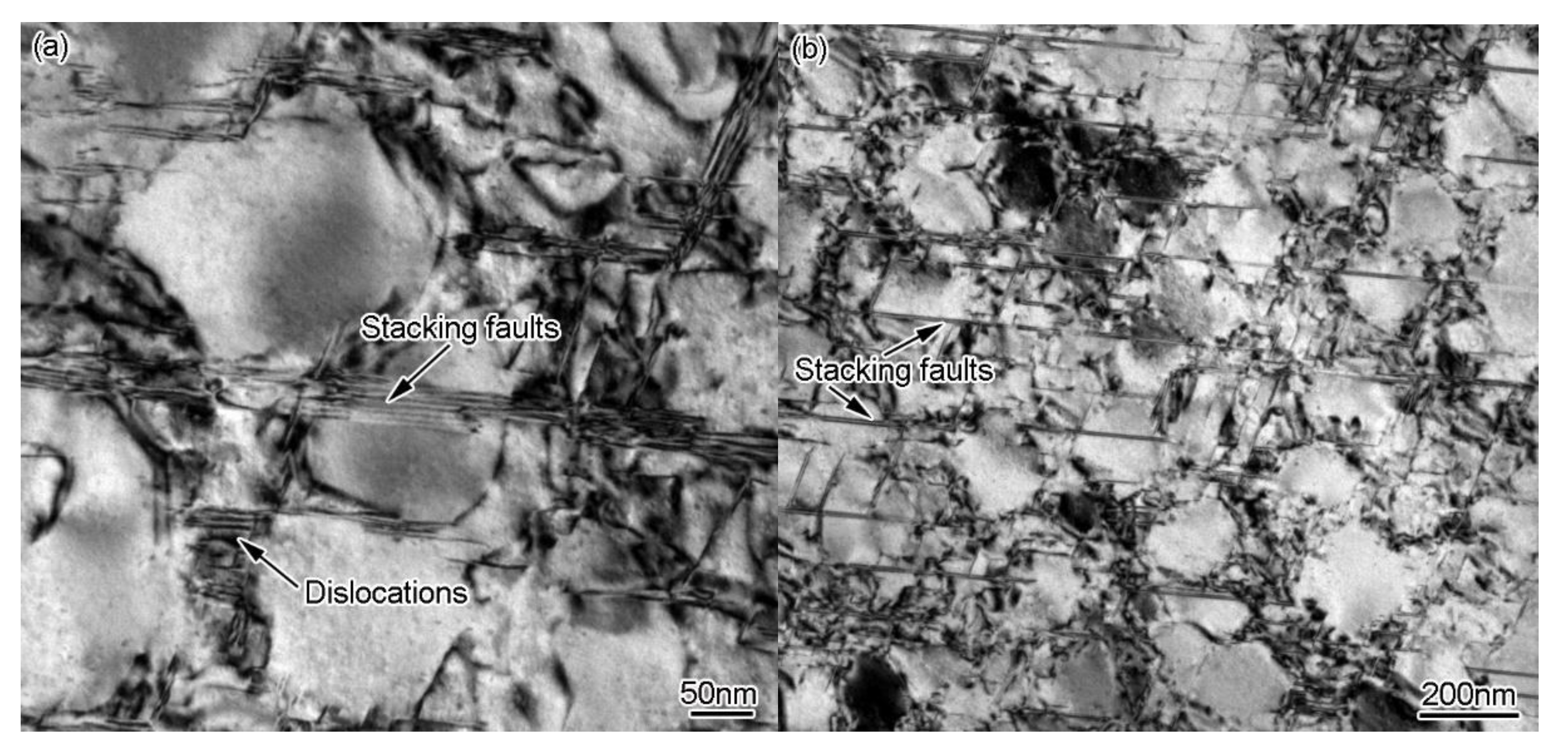
The TEM analyses of the specimens of the HIPed alloy after creep at 705 °C/897 MPa are shown in Figure 9. Figure 9a shows that the creep deformation mechanism of the HIPed alloy are dislocation and stacking fault cutting the γ′ precipitate. Figure 9b shows the continuous and wide stacking faults cutting the γ matrix and γ′ precipitate. The γ′ precipitates are obstacles to dislocation movement. As creep proceeds, the number of dislocations increases. Dislocations can be seen in the local regions cutting γ′ precipitates and forming stacking faults extending in different directions (Figure 9c) and at the intersection of partial stacking fault and anti-phase boundary (APB), as indicated by the arrows in Figure 9d. In the later stage of creep, the accumulation of a large number of dislocations near the grain boundary creates stress concentration so that the grain boundary can slide more easily. Meanwhile, the atoms on the grain boundary diffuse rapidly at a high temperature. In addition, the HIPed alloy has flat and smooth grain boundaries, which are easier to slide under stress. When the sliding grain boundaries are blocked at the trigeminal intersection of the grain boundaries, cavities occur due to stress concentration, and the cavities combine with each other to form wedge-shaped cracks. The increase in the applied stress or test temperature will accelerate the dislocation movement and grain boundary sliding, which will accelerate the initiation and propagation of grain boundary cracks in the later stage of creep, and finally accelerate the occurrence of creep fracture.
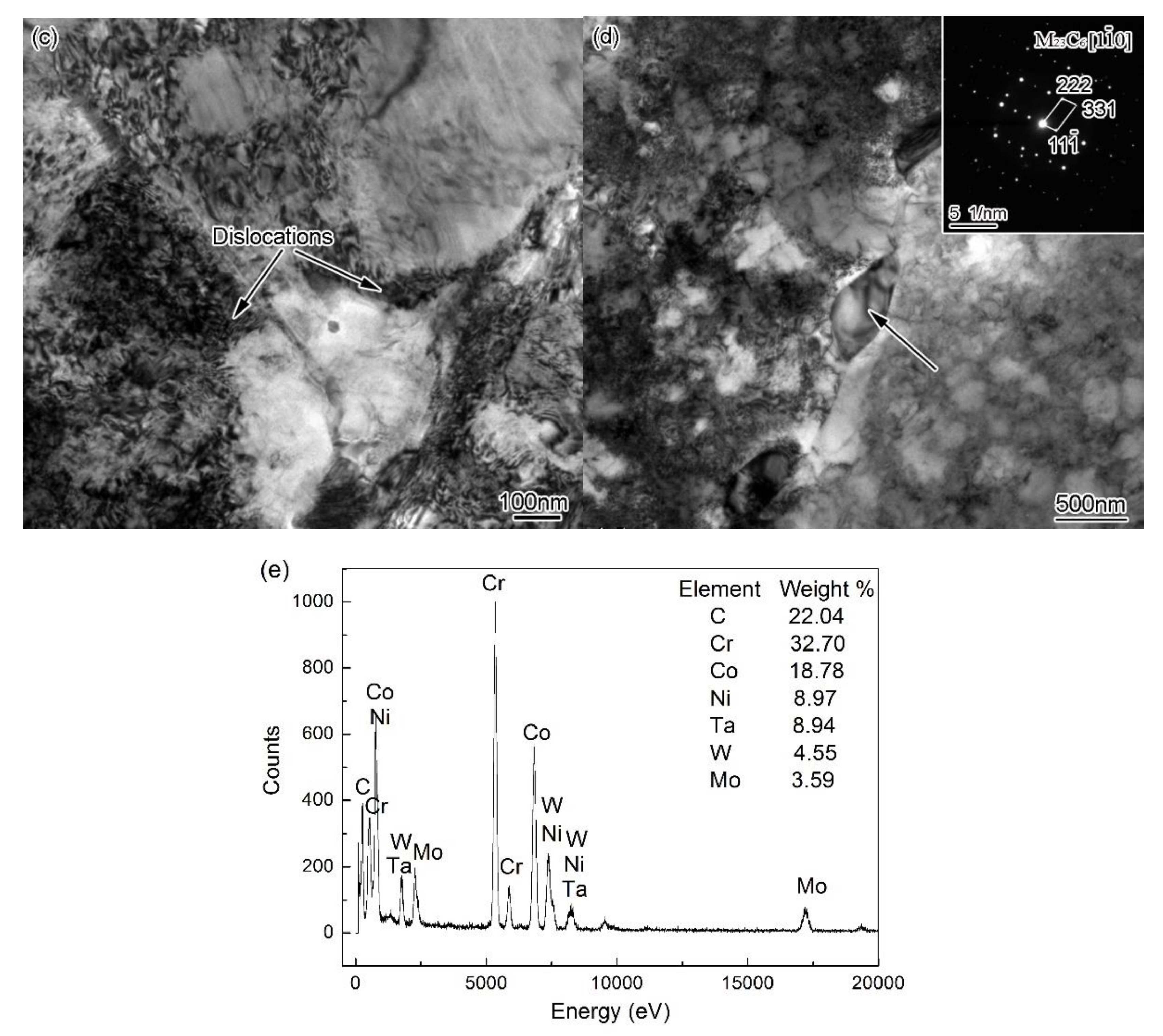
The creep deformation of the IFed alloy is dominated by dislocation and stacking fault cutting the γ′ precipitate, which hinders the creep deformation. Figure 10a shows that stacking faults cut the γ′ precipitate and a large number of dislocations accumulate around the γ′ precipitate to form stacking faults. Figure 10b shows the continuous wide stacking faults cutting the γ matrix and γ′ precipitate. Figure 10c shows a large number of dislocations packed around the γ′ precipitate. At the late stage of creep, the γ′ precipitate raft demonstrably thickens, and the creep deformation mechanism is mainly the dislocation cutting mechanism. In addition, with the further increase in the number of dislocations at the end of creep, dislocations pile up near the serrated grain boundaries and carbides (Figure 10d), which can block dislocation movement. Moreover, at the same time, stress concentration is generated. When the yield strength is reached, the cavity cracks initiate and propagate on the grain boundary and at the interface between carbides and matrix. It should be noted that grain boundaries and carbides block the propagation of cracks. Figure 10e is the energy dispersive spectrometer (EDS) of the carbide in Figure 10d. According to the analysis results of EDS and selected area electron diffraction (SAED), the carbide mainly contains C, Cr, Co, Ni, Ta, W, and Mo elements, and is an M23C6-type carbide.
Under the creep condition of 705 °C/897 MPa, the creep deformation mechanism of both HIPed and IFed alloys is dislocation and the stacking fault cutting the γ′ precipitate, which makes dislocations easier to decompose. The continuous wide stacking faults running through the γ matrix and γ′ precipitate are present in the alloy. Under the action of temperature and stress, the state of the grain boundaries and carbides in the secondary and tertiary stages of creep have a great influence on the final fracture of the alloy. This is because the micro-cracks, which cause fatal damage to the alloy, mostly germinate at the trigeminal intersection of the grain boundaries and at the interface where carbides combine with the matrix, and expand rapidly in the tertiary stage of creep. In addition, corrosion, oxidation, and other actions in the process of high-temperature creep are also important factors to enhance the alloy damage to the final fracture.

4.2. Creep Damage and Endurance Life Prediction

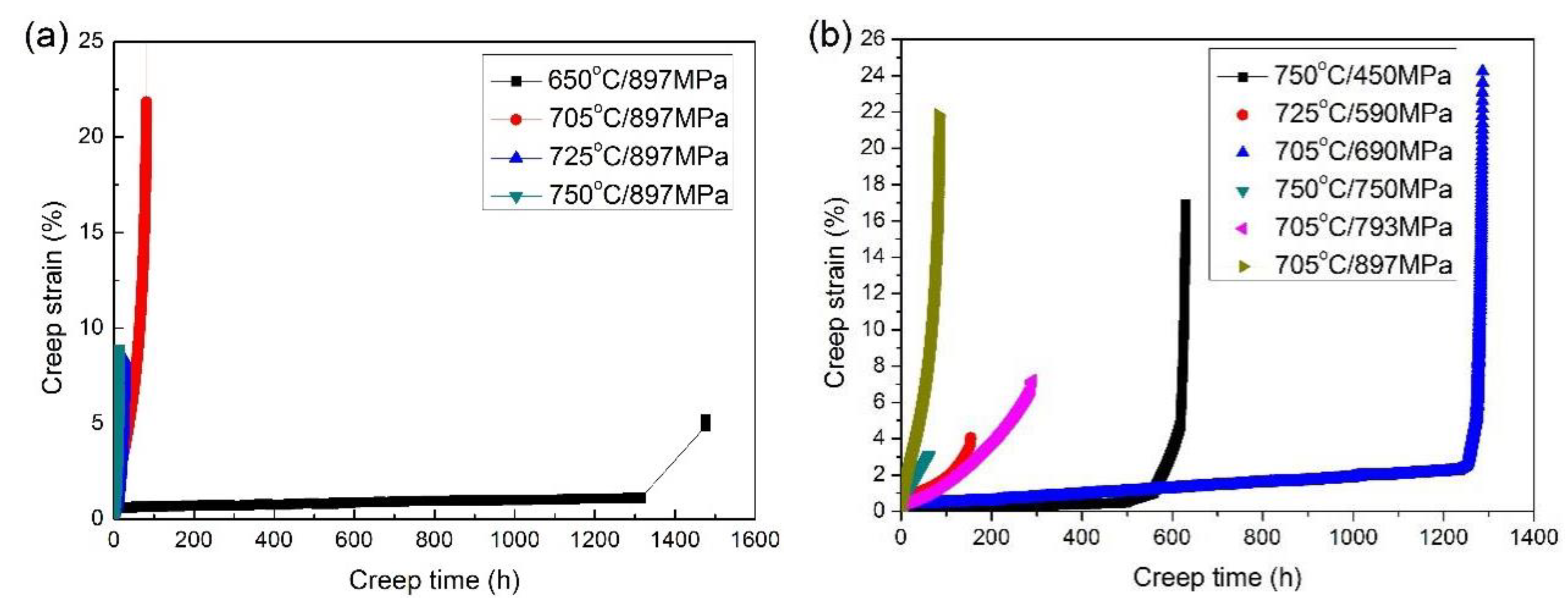
Figure 11 shows the creep curves of the IFed alloy under different stress and temperature conditions. Figure 11a shows that under the same stress load of 897 MPa, the endurance life of the alloy decreases significantly with the temperature increasing from 650 to 750 °C. It can be seen from the creep curve that the primary creep stage cannot be observed obviously, and the secondary creep stage lasts for a short time and then quickly enters the tertiary creep stage. Under the creep condition of 650 °C/897 MPa, the endurance life of FGH100L alloy is 1477.42 h, and the total strain is 5.22%. As the test temperature increases, the duration of the secondary stage of creep gradually decreases, which is about 50, 12, and 2 h at 650, 705, and 750 °C, respectively. At the tertiary stage of creep, the higher the testing temperature, the greater the creep speed, and the shorter the endurance life. The creep strain of the tertiary stage varies significantly, which reflects that temperature plays an important role on the structure evolution, crack initiation and propagation, and fracture mode. Figure 11b shows the creep curves of the alloy under different temperature and stress conditions. At 750 °C/450 MPa, the total creep strain of the alloy is 37.07%, and the alloy has a low steady-state creep rate and a long endurance life of about 629.18 h. At 705 °C/690 MPa, the alloy’s steady-state creep lasts for the longest time of about 300h with a low creep rate. The maximum creep strain is 24.99%, and the endurance life is 1286.27 h.
The above analysis shows that the creep rate of the FGH100L alloy is significantly affected by load stress and temperature. Generally, the relationship among the minimum creep rate, creep stress, and temperature complies with Norton’s formula [32,33,34].
ε s = A σ a n exp ( Q c / RT )
In Equation (1), ε s is the minimum creep rate, A is the constant related to the material microstructure, T is the absolute temperature, R is the gas constant (8.314 J/mol·K), Qc is the creep activation energy, n is the stress exponent, and σa is the applied stress.
At a given temperature, take the logarithm of both sides of Equation (1) and convert it to Equation (2):
lg ε s = n lg σ a + c
In Equation (2), c is a constant. The relationship between lg ε s and lgσa is linear in the double logarithmic coordinate, and the slope of the straight line is the stress exponent n.
When the applied stress is fixed, Equation (1) can be converted to Equation (3):
lg ε s = Q c / RT + c
In Equation (3), c′ is a constant. So, lg ε s has a linear relationship with T−1. The slope of the linear relationship between lg ε s and T−1 represents the creep activation energy.
Figure 12 shows the linear relationship between lg ε s and lgσa of the IFed alloy under the creep condition of 705 °C/690–897 MPa. The minimum creep rate of the alloy increases with the increase in the applied stress. By calculating the slope of the straight line in the figure, it can be concluded that the n value is 16.33, which is mainly related to the γ′ precipitation strengthening because a large number of dispersed γ′ precipitates hinder the movement of dislocations. The properties of grain boundaries and other factors have an important influence on the creep deformation of the alloy as well.
The linear relationship between lg ε s and T−1 is obtained, as shown in Figure 13. The steady-state creep activation energy Qc of the IFed alloy under the creep condition of 897 MPa/650–750 °C is calculated to be 339.35 kJ/mol. The self-diffusion activation energy of pure Ni in austenite is 265–285 kJ/mol, and that of polycrystalline nickel-based superalloy is about 300 kJ/mol [35]. The FGH100L alloy has a high Qc value as there is a high-volume fraction of γ′ precipitates in the alloy, which strongly affects the process of atom diffusion by hindering dislocation climbing, vacancy directional diffusion, and grain boundary sliding. The higher the Qc value, the greater the creep resistance of the alloy and the less prone it is to creep deformation. Therefore, the alloy will possess higher creep strength and longer life endurance [32].

5. Conclusions

  • Under the creep condition of 705 °C/897 MPa, the creep rupture time and strain of the IFed alloy are about 24.6 h and 5.8% higher, respectively, compared with that of the HIPed alloy, and the endurance life of the former is 1.4 times longer than that of the latter.
  • There is only one size of the cubic shaped tertiary γ′ precipitates in the HIPed alloy after creep. The phenomenon of coarsening and growing of tertiary γ′ precipitates is obvious. Some secondary γ′ precipitates coarsen to form raft structures.
  • There are two sizes of tertiary γ′ precipitates in the IFed alloy after creep. The division and coarsening of the big tertiary γ′ precipitates occurred simultaneously. Part of the big tertiary γ′ precipitates coarsened to form raft structures, with a cubic shape, that are mainly distributed in the grains. The small tertiary γ′ precipitates coarsened and were distributed in the phase boundary between the primary and secondary γ′ precipitates and the matrix. After creep, the secondary γ′ precipitates are distributed in the grains, but no raft structure of secondary γ′ precipitates is observed.
  • The fracture source areas of both HIP and IFed alloys demonstrate intergranular fracture characteristics. The difference is that the cracks in the HIPed alloy usually initiate at the trigeminal intersection of the grain boundaries and produce wedge-shaped cracks. However, the IFed alloy has serrated, curved grain boundaries, which allows cavity cracks to more easily germinate at the grain boundary and carbide interfaces.
  • Under the condition of 705 °C and 897 MPa, the creep deformation mechanism of both HIPed and IFed alloys is dislocation and the stacking fault cutting the γ′ precipitate. Continuous wide stacking faults running through the γ matrix and γ′ precipitate are present in both alloys.
  • The creep properties of the FGH100L alloy is sensitive to stress and temperature. Under the condition of 705 °C/690–897 MPa, the stress exponent n of the IFed alloy is 16.33. Under the condition of 897 MPa/650–750 °C, the creep activation energy Qc of the IFed alloy is 339.35 kJ/mol.

Author Contributions

Conceptualization, C.G. and X.L.; Data curation, T.T., X.L., Z.H., S.P. and C.J.; Investigation, T.T., Z.H. and S.P.; Project administration, C.G.; Supervision, C.G. and X.L.; Writing—original draft, T.T. and Z.H.; Writing—review & editing, C.G., X.L., S.P. and C.J. All authors have read and agreed to the published version of the manuscript.

Funding

This research was funded by the National Natural Science Foundation of China, grant number 51171016; Shenzhen Science and Technology Innovation Commission, grant number JSGG20180508152608855. The APC was funded by the National Natural Science Foundation of China.

Acknowledgments

The authors thanks the group of Udo Fritsching and Volker Uhlenwinkel of Bremen University in Germany, Zhang Yu-Chun of Fushun Special Steel Shares Co., Ltd., Ye Jun-Qing of Guizhou Anda Aviation Forging Co., Ltd., Zheng Wei-Wei of State Key Laboratory for Advanced Metals and Materials, and Chen Jin of School of Metallurgical and Ecological Engineering in University of Science and Technology Beijing, for their valuable contributions.

Conflicts of Interest

All authors declare no conflict of interest. All funders had no role in the design of the study; in the collection, analyses, or interpretation of data; in the writing of the manuscript, or in the decision to publish the results.

References

  1. Wu, R.H.; Yue, Z.F.; Wang, M. Effect of initial γ/γ′ microstructure on creep of single crystal nickel-based superalloys: A phase-field simulation incorporating dislocation dynamics. J. Alloy. Compd. 2019, 779, 326–334. [Google Scholar] [CrossRef]
  2. Pettinari-Sturmel, F.; Vultos, W.; Hantcherli, M.; Warot-Fonrose, B.; Marcelot, C.; Douin, J.; Cormier, J.; Villechaise, P.; Devaux, A. Creep behavior in the new AD730TM nickel-based disk superalloy—Influence of aging heat treatment and local chemical fluctuations. Mater. Sci. Eng. A 2019, 754, 9–17. [Google Scholar] [CrossRef]
  3. Detrois, M.; Rotella, J.; Goetz, R.L.; Helmink, R.C.; Tin, S. Grain boundary engineering of powder processed Ni-base superalloy RR1000: Inflfluence of the deformation parameters. Mater. Sci. Eng. A 2015, 627, 95–105. [Google Scholar] [CrossRef]
  4. Hu, B.F.; Liu, G.Q.; Jia, C.C.; Tian, G.F. Development in new type high performance P/M superalloys. J. Mater. Eng. 2007, 2, 49–53. (In Chinese) [Google Scholar]
  5. Timothy, J.G.; Gabb, P.; Telesman, J. Thermal and Mechanical Property Characterization of the Advanced Disk Alloy LSHR; NASA/TM-2005-213645; NASA: Washington, DC, USA, 2005; pp. 1–80. [Google Scholar]
  6. Zhang, Y.W.; Chi, Y.; Liu, J.T. Recent development of new type powder metallurgy superalloys in Russia. Powder Metall. Ind. 2015, 4, 1–14. (In Chinese) [Google Scholar]
  7. Xie, J.; Tian, S.G.; Shang, L.J.; Zhou, X.M. Creep behaviors and role of dislocation network in a powder metallurgy Ni-based superalloy during medium-temperature. Mater. Sci. Eng. A 2014, 606, 304–312. [Google Scholar] [CrossRef]
  8. Peng, Z.C.; Tian, G.F.; Jiang, J.; Li, M.Z.; Chen, Y.; Zou, J.W.; Dunne, F.P.E. Mechanistic behaviour and modelling of creep in powder metallurgy FGH96 nickel superalloy. Mater. Sci. Eng. A 2016, 676, 441–449. [Google Scholar] [CrossRef] [Green Version]
  9. Liu, C.K.; Zhou, J.Y.; Wei, Z.W.; Chen, F.; Tao, C.H. Evolution and quantitative characterization of γ′ phase in FGH97 powder metallurgy superalloy during high-temperature heat exposure. Mater. Mech. Eng. 2018, 42, 9–13. (In Chinese) [Google Scholar]
  10. Huang, H.L.; Zhang, H.F.; Hu, B.F.; Wang, H.; Liu, G.Q. Study on γ′ precipitation behavior in a nickel-based PM superalloy during interrupted continuous cooling. Intermetallics 2020, 116, 106659. [Google Scholar] [CrossRef]
  11. William, T.; Robin, M.J.; Ramesh, S. Spray Forming of Nickel Superalloys. In Metal Sprays and Spray Deposition, 1st ed.; Henein, H., Uhlenwinkel, V., Fritsching, U., Eds.; Springer International Publishing AG: Cham, Switzerland, 2017; pp. 497–520. [Google Scholar]
  12. Zhu, Z.; Basoalto, H.; Warnken, N.; Reed, R.C. A model for the creep deformation behaviour of nickel-based single crystal superalloys. Acta Mater. 2012, 60, 4888–4900. [Google Scholar] [CrossRef]
  13. Zhang, P.; Li, J.; Gong, X.F.; Yuana, Y.; Gu, Y.F.; Wang, J.C.; Yan, J.B.; Yin, H.F. Creep behavior and deformation mechanisms of a novel directionally solidified Ni-base superalloy at 900 °C. Mater. Charact. 2019, 148, 201–207. [Google Scholar] [CrossRef]
  14. Li, Y.F.; Wang, L.; Zhang, G.; Zhang, J.; Lou, L.H. Creep anisotropy of a 3rd generation nickel-base single crystal superalloy at 850 °C. Mater. Sci. Eng. A 2019, 760, 26–36. [Google Scholar] [CrossRef]
  15. Zhao, G.Q.; Tian, S.G.; Zhang, S.K.; Tian, N.; Liu, L.R. Deformation and damage features of a Re/Ru- containing single crystal nickel base superalloy during creep at elevated temperature. Prog. Nat. Sci. 2019, 29, 210–216. [Google Scholar] [CrossRef]
  16. Song, W.; Wang, X.G.; Li, J.G.; Ye, L.H.; Hou, G.C.; Yang, Y.H.; Liu, J.L.; Liu, J.D.; Pei, W.L.; Zhou, Y.Z.; et al. Effect of ruthenium on microstructure and high-temperature creep properties of fourth generation Ni-based single-crystal superalloys. Mater. Sci. Eng. A 2019, 772, 1–26. [Google Scholar] [CrossRef]
  17. Wu, J.; Li, C.; Liu, Y.C.; Wu, Y.T.; Guo, Q.Y.; Li, H.J.; Wang, H.P. Effect of annealing treatment on microstructure evolution and creep behavior of a multiphase Ni3Al-based superalloy. Mater. Sci. Eng. A 2019, 743, 623–635. [Google Scholar] [CrossRef]
  18. Yue, Q.Z.; Liu, L.; Yang, W.C.; He, C.; Sun, D.J.; Huang, T.W.; Zhang, J.; Fu, H.Z. Stress dependence of the creep behaviors and mechanisms of a third-generation Ni-based single crystal superalloy. J. Mater. Sci. Technol. 2019, 35, 752–763. [Google Scholar] [CrossRef]
  19. Huo, J.J.; Shi, Q.Y.; Feng, Q. Effect of multiple alloying additions on microstructural features and creep performance at 950 °C and 400 MPa in Ru-containing single crystal superalloys. Mater. Sci. Eng. A 2017, 693, 136–144. [Google Scholar] [CrossRef]
  20. Tian, S.G.; Wu, J.; Shu, D.; Su, Y.; Yu, H.C.; Qian, B.J. Influence of element Re on deformation mechanism within γ′ precipitate of single crystal nickel-based superalloys during creep at elevated temperatures. Mater. Sci. Eng. A 2014, 616, 260–267. [Google Scholar] [CrossRef]
  21. Lv, X.Z.; Zhang, J.X. Core Structure of a <100> interfacial superdislocations in a nickel-base superalloy during high-temperature and low-stress creep. Mater. Sci. Eng. A 2017, 683, 9–14. [Google Scholar] [CrossRef]
  22. Mohammad, A.; Mahboobeh, A. Evaluation of high-temperature creep behavior in Inconel-713C nickel based superalloy considering effects of stress levels. Mater. Sci. Eng. A 2017, 689, 298–305. [Google Scholar]
  23. Wollgramm, P.; Buck, H.; Neuking, K.; Parsa, A.B.; Schuwalow, S.; Rogal, J.; Drautz, R.; Eggeler, G. On the role of Re in the stress and temperature dependence of creep of Ni-base single crystal superalloys. Mater. Sci. Eng. A 2015, 628, 382–395. [Google Scholar] [CrossRef]
  24. Viswanathan, G.B.; Sarosi, P.M.; Mills, M.J. Deformation mechanisms at intermediate creep temperatures in the Ni-base superalloy Rene 88DT. Mater. Sci. Eng. A 2005, 400, 489–495. [Google Scholar] [CrossRef]
  25. Jia, C.L.; Zhang, F.L.; Wei, K.; Lv, S.M. Effective solution treatment can result in improved creep performance of superalloys. J. Alloy. Compd. 2019, 770, 166–174. [Google Scholar] [CrossRef]
  26. Jia, C.L.; Li, Y.; Zhang, F.L.; Lv, S.M. The creep behavior of a disk superalloy under different stress conditions. Metal Powder Rep. 2018, 73, 94–100. [Google Scholar] [CrossRef]
  27. China National Standardization Administration. Metallic Materials—Uniaxial Tensile Creep Test Method for Metallic Materials; GBT 2039-2012; China Standard Press: Beijing, China, 2012; pp. 1–38. (In Chinese) [Google Scholar]
  28. Tian, T.; Hao, Z.B.; Jia, C.L.; Ge, C.C. Microstructure and properties of a new third generation powder metallurgy superalloy FGH100L. Acta. Metall. Sin. 2019, 55, 1260–1272. [Google Scholar]
  29. Jia, J.; Tao, Y.; Zhang, Y.W.; Zhang, Y. Reverse coarsening splitting behavior of the secondary γ′ in superall- oy FGH 95 during long-term aging. Rare Metal Mat. Eng. 2012, 41, 1156–1160. (In Chinese) [Google Scholar]
  30. Xie, J.; Tian, S.G.; Li, J.J. Influence of γ/γ′ lattice misfit on creep behaviors of FGH95 Ni-based superalloy. Mater. Sci. Technol. 2013, 9, 1021–1026. [Google Scholar] [CrossRef]
  31. Xie, J.; Tian, S.G.; Zhou, X.M. Effect of HIP temperature on microstructure and creep property of FGH- 95 alloy. High Tem. Mater. Processes 2012, 31, 61–66. [Google Scholar]
  32. Guo, J.T.; Yuan, C.; Hou, J.S. Creep and creep-fatigue-environment interaction and mechanisms of superalloys. Chin. J. Nonferrous Metals 2011, 3, 25–42. [Google Scholar]
  33. McLean, D. Mechanical Properties of Metals; John Wiley & Sons Inc.: Hoboken, NJ, USA, 1962; pp. 308–311. [Google Scholar]
  34. Kim, W.G.; Park, J.Y.; Ekaputra, I.; Kim, S.J.; Kim, M.H.; Kim, Y.W. Creep deformation and rupture behavior of Alloy 617. Eng. Fail. Anal. 2015, 58, 441–451. [Google Scholar] [CrossRef]
  35. Davies, S.J.; Jeffs, S.P.; Coleman, M.P.; Lancaster, R.J. Effects of heat treatment on microstructure and creep properties of a laser powder bed fused nickel superalloy. Mater. Des. 2018, 159, 39–46. [Google Scholar] [CrossRef]
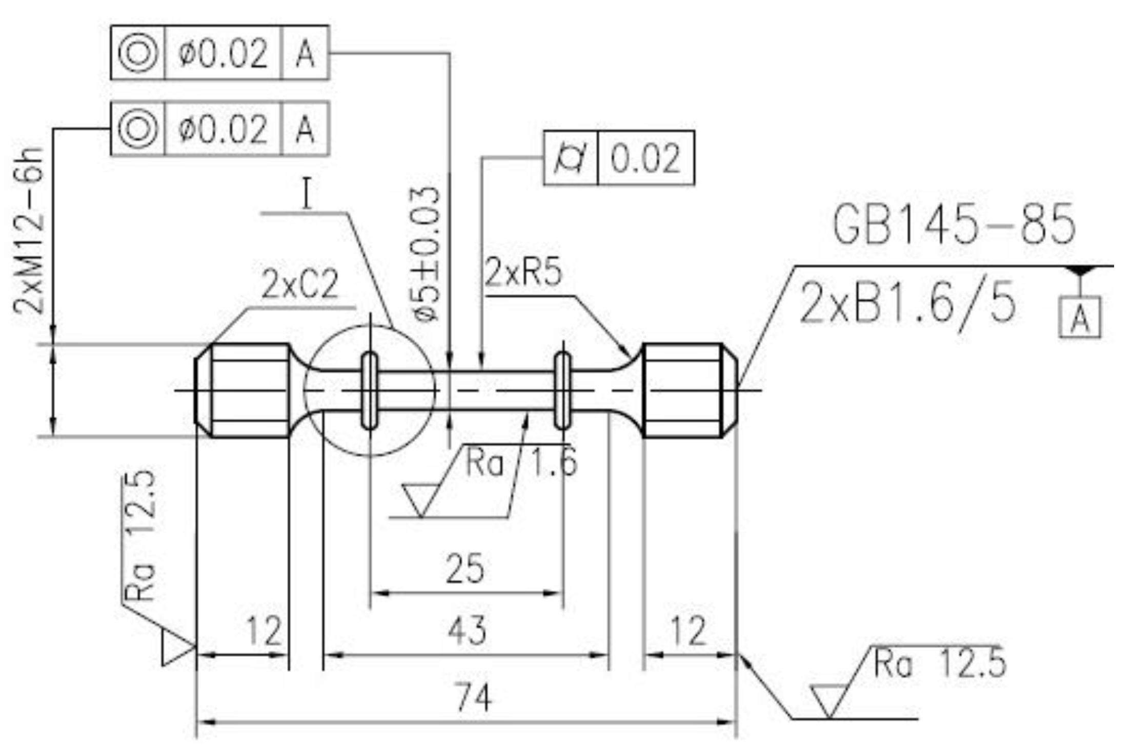
Figure 1. Processing diagram of creep specimen.
Metals 10 00454 g001
Figure 2. Creep curves of FGH100L alloy at 705 °C/897 MPa: (a) a comparison of strain–time relationships between the two processes, (b) the relationship between creep rate and the time of the HIPed alloy, and (c) the relationship between creep rate and the time of the IFed alloy.
Metals 10 00454 g002
Figure 3. Initial microstructures of FGH100L alloy before creep: (a) optical microscopy (OM) images of HIPed alloy, (b) OM images of IFed alloy, (c,e) SEM images of HIPed alloy, and (d,f) SEM images of IFed alloy.
Metals 10 00454 g003aMetals 10 00454 g003b
Figure 4. Microstructures of FGH100L alloy after creep at 705 °C/897 MPa: (a) OM images of HIPed alloy, (b) OM images of IFed alloy, (ce) SEM images of HIPed alloy, and (fh) SEM images of IFed alloy.
Metals 10 00454 g004
Figure 5. Fracture morphology of HIPed alloy after creep at 705 °C/897 MPa: (a) low magnification morphology, (b) fracture source region, (c) propagation region, (d) shear lip region.
Metals 10 00454 g005
Figure 6. Fracture morphology of IFed alloy after creep at 705 °C/897 MPa: (a) low magnification morphology, (b) the fracture source region, (c) the propagation region, the arrow shows small steps with deep interlaced slip traces, and (d) the shear lip region.
Metals 10 00454 g006aMetals 10 00454 g006b
Figure 7. Fracture morphology of HIPed alloy after the stress-rupture at 705 °C/897 MPa: (a) low magnification morphology, (b) the fracture source region, (c) steps and small planes in the propagation region, (d) tearing edges and steps in the propagation region, and (e) the shear lip region.
Metals 10 00454 g007aMetals 10 00454 g007b
Figure 8. Fracture morphology of IFed alloy after the stress-rupture condition at 705 °C/897 MPa: (a) low magnification morphology, (b) the fracture source region, (c) small planes in the propagation region, (d) tearing edges and small planes in the propagation region, (e) the shear lip region.
Metals 10 00454 g008aMetals 10 00454 g008b
Figure 9. Transmission electron microscopy (TEM) images of dislocation morphology in HIPed alloy after creep under the condition of 705 °C/897 MPa: (a) dislocations and stacking faults, (b,c) stacking faults, and (d) the anti-phase boundary (APB).
Metals 10 00454 g009aMetals 10 00454 g009b
Figure 10. TEM images of dislocation morphology in IFed alloy after creep at 705 °C/897 MPa: (ac) dislocations and stacking faults, (d) carbides and selected area electron diffraction (SAED), and (e) the energy dispersive spectrometer (EDS) of carbide in (d).
Metals 10 00454 g010aMetals 10 00454 g010b
Figure 11. Creep curves of IFed alloy under different stress and temperature conditions: (a) 897 MPa/650–750 °C and (b) 450–897 MPa/705–750 °C.
Metals 10 00454 g011
Figure 12. Relationship of the lg ε s -lgσa of IFed alloy at 705 °C/690–897 MPa.
Metals 10 00454 g012
Figure 13. Relationship of the lg ε s -T−1 of IFed alloy at 897 MPa/650–750 °C.
Metals 10 00454 g013
Table 1. Comparison of creep properties of FGH100L alloy under different processes.
Preparation ProcessTemperature (°C)Stress (MPa)Rupture Life (h) Strain (%)
HIP70589756.9616.0
HIP + IF750450629.1837.1
7056901286.2724.9
793290.467.2
89781.5421.9
Table 2. The stress-rupture properties of FGH100L alloy under different processes.
Preparation ProcessTest ConditionsStress-Rupture Life (h)Elongation (%)
HIP705 °C/897 MPa47.812
HIP + IF705 °C/897 MPa66.514
Table 3. Density and relative density of FGH100L alloys under different processes.
Preparation ProcessAverage Density/(g·cm−3)Relative Density/%
SF97.33
HIP8.2398.44
HIP+IF8.2999.16
Table 4. Statistics of average grain size and γ′ precipitate size before and after the creep of FGH100L alloy in different processes.
ProcessBefore CreepAfter Creep
Grain SizePrimary γ′Secondary γ′Tertiary γ′Grain SizePrimary γ′Secondary γ′Tertiary γ′
HIP40.73 μm1.98 μm0.84 μmB-tertiary γ′ 0.14 μm; S-tertiary γ′ 0.06 μm54.44 μm2.32 μm1.18 μm0.23 μm
IF24.25 μm1.75 μm0.52 μmB-tertiary γ′ 0.08 μm; S-tertiary γ′ 0.01 μm37.24 μm1.72 μm0.62 μmB-tertiary γ′ 0.24 μm; S-tertiary γ′ 0.06 μm