Abstract
In order to understand the work hardening phenomenon and mechanism of laser-assisted machining (LAM) of Si3N4 ceramics, the work hardening degree of LAM Si3N4 under different material removal modes was studied. Two sets of single-factor experiments were performed in which the laser power and the cutting depth were changed respectively. The results show that work hardening is the result of the combination of heat and cutting deformation during cutting. The work hardening degree decreases with the increase of material softening degree. When the material is removed plastically, the work hardening degree is 110–115%.
1. Introduction
Engineering ceramics have many excellent properties, such as high strength, high hardness, corrosion resistance, wear resistance, ablation resistance, and a low thermal expansion coefficient, and these properties can be maintained well at high temperatures. Therefore, they are important materials in the fields of space technology, military technology, atomic energy, industry and chemical equipment, etc. [1,2]. Silicon nitride (Si3N4) is a typical engineering ceramic. However, because of their inherently high strength, high hardness, and high brittleness, a very high cutting force and cutting temperature are required/produced when engineering ceramics are cut by traditional machining methods. As a result, micro cracks will be produced on the machined surface, which greatly reduces the service performance of engineering ceramics parts, and the tool life will be reduced. The root cause is that machining is done in the brittle region, not in the plastic region. Extensive experiments conducted on various ceramics, such as Si3N4 [3,4,5,6,7,8,9], aluminum oxide (Al2O3) [10,11], zirconia (ZrO2) [12], and other ceramic composite materials [13,14,15,16,17], have proven that laser-assisted machining (LAM) is an effective method to solve the above problems. The high-power laser beam focused on the surface of the ceramic material can heat the material to a very high temperature in a short time before the material is cut, soften the material, reduce the yield strength to below the fracture strength, and then change the cutting performance of the material. Thus, the transition from brittleness to plasticity is achieved. Additionally, only when the workpiece is heated to a suitable softening state can the material be removed plastically, and then better surface integrity and longer tool life can be achieved. If the heating temperature is too high, the machined surface can be burned by excessive heat. If the temperature is too low, the workpiece will not be softened sufficiently, and the material will still be removed in the way of brittle fracture.
Shin et al. [3,4,5] studied the removal mechanisms, the thermo-mechanical characteristics, and the surface integrity of Si3N4 in LAM. Under the irradiation of a laser, with the increase of workpiece temperature, the viscosity of the intergranular glass phase decreases. When the temperature exceeds the glass transition temperature, Si3N4 grains are repositioned, and the fluid glass-phase material flows to form a new grain boundary under the action of cutting tools. Thus, the material is plastically removed. Among the operating parameters, laser power has the most important effect on the temperature of the workpiece, followed by the cutting depth. When the material is plastically removed, the machined parts have low surface roughness, moderate compressive residual stress, and no surface/subsurface microcracks or thermal damage. LAM can achieve lower cutting forces and specific cutting energy, longer tool life, and higher material removal rates. Damage-free silicon nitride parts with complex geometric features were machined, which further proved the feasibility and advantages of LAM. Kang and Lee [6] studied the laser-assisted milling process of Si3N4. A new back-and-forth preheating method was proposed, and a constitutive equation was determined. Lee et al. [7] studied the microstructural variations, the machining characteristics, and the oxidation mechanism of Si3N4 from increasing the temperature. Wu [8] investigated the laser absorption and heat conduction process in LAM Si3N4, performed laser-assisted turning and laser-assisted milling of Si3N4 experiments, and analyzed the surface integrity. Pu et al. [9] analyzed comprehensively, the chips, tool wear, and the machined surface under different material removal modes in LAM Si3N4. When the material is plastically removed, the chips are continuously band-like. Tool wear occurs on the rake face. The surface is smooth with no cracks or pits. When thermal damage occurs, band-like chips are longer. Tool wear can barely be seen, and the surface has a porous structure. When the material is removed through a brittle fracture, the chips become particle-like. The cutting edge is tipped, and cracks or pits can be seen on the surface.
As one of the important contributors to surface integrity, work hardening refers to the phenomenon of the hardness of the machined surface and subsurface of workpiece increasing due to the cutting process. Moderate work hardening can improve the wear resistance. However, work hardening reduces the ductility and toughness of the parts, and microcracks can be produced on the surface because of over work hardening, which reduces the fatigue life of the parts. Therefore, research on work hardening is required. Extensive research has been conducted on the work hardening mechanism of metal material cutting. S.Y. Wang [18] argued that plastic deformation, cutting heat, and phase transformation are the primary factors that affect work hardening. However, there is hardly any literature on the work hardening mechanism of ceramic materials in LAM.
In this paper, the micro-hardnesses of LAM-machined Si3N4 surfaces under different material removal modes are comprehensively characterized and compared. The degree of hardening under different material removal modes was found, and the mechanism of work hardening was analyzed.
2. LAM Experiment
2.1. Experimental System
The experimental system of LAM Si3N4 is shown in Figure 1. The continuous laser with wavelength of 1070 nm emitted by the ytterbium fiber laser (YLR-150/1500-QCW-MM-AC, IPG Photonics Co., Oxford, OH, USA) was focused on the surface to be machined by the laser optical focusing system fixed on the apron of the CNC turret lathe (CKD6136i, Dalian Machine Tools Group, Dalian, China). In continuous wave mode, the maximum average power can reach 250 W. The diameter of the laser spot on the workpiece surface can be changed by adjusting the relative position between the focusing system and the workpiece. The relative position of the laser spot and the cutting tool remains unchanged, and they can move synchronously. MCLNR2020K12 tool holders with CBN-tipped carbide tool inserts (CNGA120408 BNK30, Halnn Superhard, Zhengzhou, China) were used for all of the cutting operations.
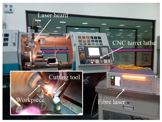
Figure 1.
Experimental system for LAM of silicon nitride.
2.2. Experimental Material
The gas-pressure sintered Si3N4 workpiece (Acro New Materials (Dalian) Co., Ltd., Dalian, China) was cylindrical, and was held using a three-jaw chuck. The size was Φ10 mm × 100 mm. The material’s properties are listed in Table 1, and these values were measured by the material’s manufacturer.

Table 1.
Properties of Si3N4 workpieces (The reference standard is ASTM F 2094).
2.3. Test Matrix and Operating Parameters
A single-factor experimental matrix was created in which only the laser power was changed. When the other parameters are fixed, different workpiece temperatures can be obtained by changing the laser power. In other words, different laser powers correspond to different material removal modes. The experimental parameters used are reported in Table 2. V, f, d, and l represent the cutting speed, the feed, the depth of the cut, and the length of the cut, respectively. The laser power (P), the preheating time (t), the diameter of the laser faculae (D), the laser-tool axial distance (L), and the circumferential laser-tool angle (φ) were selected based on a simulation and previous studies. Figure 2 is the schematic diagram of the relative position of the laser optics, the cutting point, and the workpiece.
Table 2.
Operating conditions for LAM experiments.
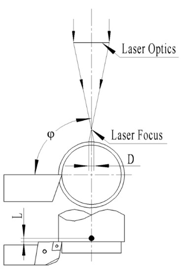
Figure 2.
The schematic diagram of the relative position of the laser optics, the cutting point, and the workpiece.
In order to ensure the accuracy of the cutting depth, two layers of ceramic material were removed in each experiment. Between the two processes, the workpieces ensure adequate cooling. After the second cutting, the chips, tool wear, and machined surfaces were analyzed to infer the removal mode of the materials. Each group of parameters was repeated twice.
In [9], it was concluded that when the laser power was between 195 W and 135 W, the material was removed plastically; when the laser power was over 195 W, thermal damage occurred; and when the laser power was lower than 135 W, brittle fracture became the main removal mode of the material.
3. Results and Discussion
3.1. Microstructural Observations and EDS Analysis
Microstructural features were studied using a scanning electron microscope (SEM, Quanta 250, FEI, Portland, OR, USA). The SEM was equipped with an energy dispersive spectrometry (EDS) system to obtain information on the chemical composition. It can be seen from the SEM images of the machined surface shown in Figure 3 that when the laser power is 225 W, the porous structure formed by the burst of nitrogen bubbles under the surface indicates the oxidation of the surface. This conclusion is consistent with the study of the oxidation mechanism of Si3N4 by Lee et al. [7]. When the laser power is 195 W, 100 W, and 40 W, the machined surfaces are not porous. Table 3 shows the mass percentages of the main elements under different laser powers in EDS analysis. When the laser power is 225 W, the content of oxygen element is much higher than that of the raw material, while the content of nitrogen is much lower than that of the raw material. Thus, it can be concluded that when the laser power is 225 W, excessive heat causes phase change.
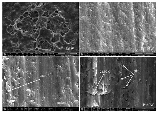
Figure 3.
The SEM images of the machined surface under different laser powers.
Table 3.
The mass percentage of the main elements in EDS analysis under different laser powers.
Figure 4 is the SEM images of the cross section of the machined surface. The sample was prepared by sectioning with a diamond blade, polishing with diamond abrasive powder, and finely coating with gold. Under the irradiation of a laser, with the increase of the softening degree of the workpiece, the rod-shaped Si3N4 grains begin to slip and rotate, and the glass phase flows along the newly formed grain boundaries to form a new surface. Thus, the thin smearing layer of the softened glass phase can be formed on the machined surface. The lighter part is the smearing layer in Figure 4, about 2 µm. The cross-sections without microcracks in Figure 4 prove once again that the material is removed by plasticity when the laser power is 195 W, 165 W, or 135 W.
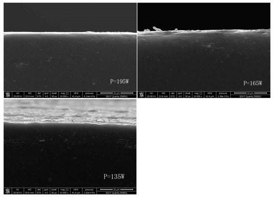
Figure 4.
SEM micrographs of a section view of the machined surface under different laser powers.
3.2. XRD Analysis and Raman Analysis
X-ray diffraction analysis (XRD, Bruker AXS D8 Advance, Germany) was carried out to analyze the phase composition of the machined surface. The test conditions were CuKɑ, 40 KV, 20 mA, and 2°/min. The XRD patterns plotted in Figure 5 show the presence of β-Si3N4 grains and glass phase (Y10Al2Si3O18N4). The glass phase is the dominant phase because the smearing layer covered on the β-Si3N4 grain.
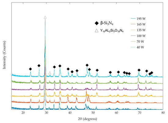
Figure 5.
The XRD patterns of the machined surface.
Raman analysis (HR Evolution, Paris, France) with an output wavelength of 532 nm and an output power of 25 mW was also used to analyze the machined surface. The results are shown in Figure 6. It has been proven that the peaks at 188 cm−1, 210 cm−1, and 230 cm−1 are all caused by the lattice vibration of β-Si3N4 [19]. The peak at 450 cm−1 is caused by the vibration of Si-O bond [20]. In this test, it is the Si-O bond in the Y10Al2Si3O18N4 phase. The positions of Raman peaks in this experiment are compared with those reported in the literatures, as shown in Table 4. It can be seen that the position of the Raman spectrum peak in this paper is basically the same as that reported in the literature, and the slight difference is the systematic error caused by the instrument calibration. In Figure 6, β-Si3N4 grains are the dominant phase because β-Si3N4 grains are crystal, and Y10Al2Si3O18N4 is not.
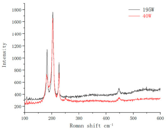
Figure 6.
The Raman spectrum of the machined surface.
Table 4.
Peak position comparison of Raman spectrum.
Based on the above analysis, it can be concluded that when the laser power is 225 W, the high laser power causes the phase transition of the machined surface. When the laser power is between 195 W and 40 W, there is no phase transformation on the machined surface
3.3. Work Hardening Degree
The micro-hardness of the workpiece was examined using a FM-800 (Future-Tech, Ishikawa-ken, Japan) micro-hardness tester with 9.8 N and 15 s dwell time. Ten random points of each workpiece were selected for measurement. The two maximum values and the two minimum values were removed, and the remaining values were averaged. The average value of two workpieces is the micro-hardness corresponding to this group of parameters. Work hardening degree NH can be simply defined as the ratio of the micro-hardness of the machined surface to the micro-hardness of the as-received workpiece.
where is the micro-hardness of the machined surface, and is the micro-hardness of the as-received workpiece. The measured micro-hardness value of the as-received workpiece is 1622 HV. When the laser power is 40 W, the maximum work hardening degree is 120%; when the laser power is 250 W, the minimum work hardening degree is 100.4%. When the material is removed plastically, the work hardening degree is 110–115%. Figure 7 shows the micro-hardness of the machined surface and the degree of work hardening under different laser powers. With the decrease of laser power, the surface micro-hardness and the degree of work hardening increase gradually.
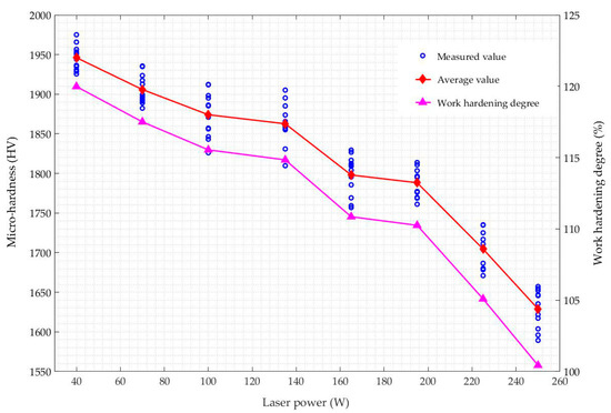
Figure 7.
The micro-hardness of the machined surface and the degree of work hardening under different laser powers.
In summary, the work hardening degree decreases with the increase of material softening degree.
3.4. Mechanism
LAM is a time-varying, nonlinear, intense thermo-mechanical coupling process. Work hardening is the result of the combination of heat and cutting deformation during cutting, as follows:
(1) When there is thermal damage, phase transformation occurs on the machined surface, and porous structure reduces the degree of work hardening. When the material is removed by plastic deformation or through brittle fractures, work hardening has nothing to do with phase transformation.
(2) The deformation resistance in the cutting process is the main cause of work hardening. According to Lei et al. [3,5], when the other parameters are fixed, the higher the laser power is, the higher the temperature of the workpiece is, the lower the viscosity of the glass phase is, and the easier the machining is. The cutting force and specific cutting energy decrease with the increase of workpiece softening, so the degree of work hardening increases with the decrease of laser power.
(3) The smearing layer of the softened glass phase on the machined surface is also one of the factors affecting work hardening. The relationship between the thickness of the smearing layer and the work hardening degree needs further study.
(4) The extrusion and friction during the cutting increase the compactness of the workpiece surface, leading to an increase in surface hardness.
4. Experimental Verification
In order to verify the conclusion that the work hardening degree decreases with the increase of material softening degree, another set of single-factor experiments was performed, which only changed the cutting depth. The laser power was fixed at 195 W, the cutting depths were 0.1 mm and 0.3 mm respectively, and other parameters were the same as the experiments in Section 2.3. Therefore, the experiment with the cutting depth of 0.2 mm was Case 3 in Table 2. Under the irradiation of the laser, the temperature gradually decreases from the surface of the workpiece to the heart. As the cutting depth increases, the softening degree of the cutting area decreases. The band-like chips shown in Figure 8 indicate that the material was not removed through a brittle fracture. It can be seen from Figure 9 that when the cutting depth is 0.1 mm, the porous structure on the surface indicates that thermal damage has occurred at this state. When the cutting depth is 0.3 mm, no cracks or pits can be seen on the machined surface, and it can be inferred that the material is plastically removed without thermal damage. The relationship between the micro-hardness and the cutting depth shown in Figure 10 shows that the work hardening degree increases with the increase of the cutting depth, which is consistent with the above conclusion.
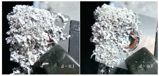
Figure 8.
Macrographs of chips under different cutting depths. (Reference dimension: the edge length of the insert is 12 mm).
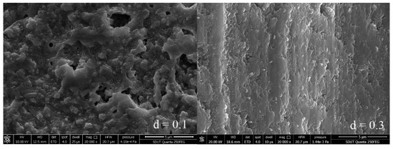
Figure 9.
The SEM images of the machined surface cut to different depths.
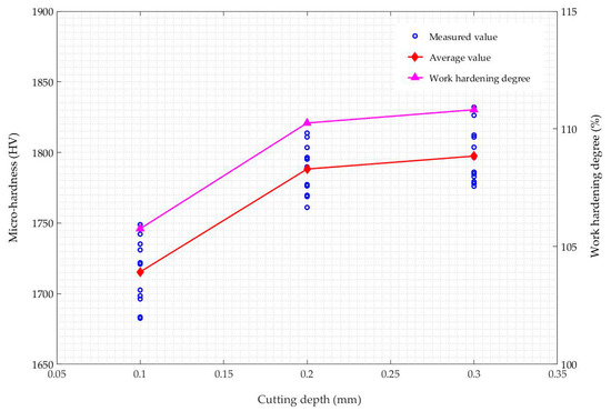
Figure 10.
The micro-hardness of the machined surface and the degree of work hardening under different cutting depths.
5. Conclusions
(1) The work hardening degree increases with the decrease of softening degree. When the material is removed plastically, the work hardening degree is 110–115%.
(2) Work hardening is the result of the combination of heat and cutting deformation during cutting. When the material is removed by plastic deformation or through brittle fractures, work hardening is not caused by phase transformation. Deformation resistance, which decreases with the softening degree of the material, causes work hardening, and the work hardening degree decreases with the increase of material softening degree. The smearing layer of the softened glass phase on the surface also has an effect on work hardening. The increase of compactness caused by extrusion and friction is one of the reasons for the increase of surface micro-hardness.
Author Contributions
Conceptualization, Y.P., Y.Z., and H.Z.; methodology, Y.P., Y.Z., and H.Z.; software, Q.L.; validation, G.Z. and J.M.; data curation, P.S.; writing—original draft preparation, Y.P.; writing—review and editing, Y.P.; supervision, Y.Z.; project administration, Y.Z.; funding acquisition, Y.Z. All authors have read and agreed to the published version of the manuscript.
Funding
This research was funded by the National Natural Science Foundation of China (grant number 51875328) and the Natural Science Foundation of Shandong Province (grant number ZR201807060394).
Acknowledgments
The authors would like to acknowledge the support of the National Natural Science Foundation of China (grant number 51875328) and the Natural Science Foundation of Shandong Province (grant number ZR201807060394). The authors would also like to thank Hong Guo for his kind help with the measurements.
Conflicts of Interest
The authors declare that they have no competing financial interests or personal relationships that could have appeared to influence the work reported in this paper.
References
- Ferraris, E.; Vleugels, J.; Guo, Y.B.; Bourell, D.; Kruth, J.P.; Lauwers, B. Shaping of engineering ceramics by electro, chemical and physical processes. CIRP Ann. 2016, 65, 761–784. [Google Scholar] [CrossRef]
- Samant, A.N.; Dahotre, N.B. Laser machining of structural ceramics—A review. J. Eur. Ceram. Soc. 2009, 29, 969–993. [Google Scholar] [CrossRef]
- Lei, S.; Shin, Y.C.; Incropera, F.P. Deformation mechanisms and constitutive modeling for silicon nitride undergoing laser-assisted machining. Int. J. Mach. Tools Manuf. 2000, 40, 2213–2233. [Google Scholar] [CrossRef]
- Tian, Y.; Shin, Y.C. Laser-Assisted Machining of Damage-Free Silicon Nitride Parts with Complex Geometric Features via In-Process Control of Laser Power. J. Am. Ceram. Soc. 2006, 89, 3397–3405. [Google Scholar] [CrossRef]
- Lei, S.; Shin, Y.C.; Incropera, F.P. Incropera, Experimental Investigation of ThermoMechanical Characteristics in Laser-Assisted Machining of Silicon Nitride Ceramics. J. Manuf. Sci. Eng. 2000, 123, 639–646. [Google Scholar] [CrossRef]
- Kang, D.W.; Lee, C.M. A study on the development of the laser-assisted milling process and a related constitutive equation for silicon nitride. CIRP Ann. 2014, 63, 109–112. [Google Scholar] [CrossRef]
- Lee, S.J.; Kim, J.D.; Suh, J. Microstructural variations and machining characteristics of silicon nitride ceramics from increasing the temperature in laser assisted machining. Int. J. Precis. Eng. Manuf. 2014, 15, 1269–1274. [Google Scholar] [CrossRef]
- Wu, X.F. Basic Research on Laser Assisted Machining of Silicon Nitride Ceramics; Harbin Institute of Technology: Harbin, China, 2011. [Google Scholar]
- Pu, Y.Z.; Zhao, Y.G.; Zhang, H.Y.; Zhao, G.Y.; Meng, J.B.; Song, P.P. Study on the three-dimensional topography of the machined surface in laser assisted machining of Si3N4 ceramics under different material removal modes. Ceram. Int. 2020, 46, 5695–5705. [Google Scholar] [CrossRef]
- Chang, C.-W.; Kuo, C.-P. Evaluation of surface roughness in laser-assisted machining of aluminum oxide ceramics with Taguchi method. Int. J. Mach. Tools Manuf. 2007, 47, 141–147. [Google Scholar] [CrossRef]
- Chang, C.-W.; Kuo, C.-P. An investigation of laser-assisted machining of Al2O3 ceramics planing. Int. J. Mach. Tools Manuf. 2007, 47, 452–461. [Google Scholar] [CrossRef]
- Kizaki, T.; Ito, Y.; Tanabe, S.; Kim, Y.; Sugita, N.; Mitsuishi, M. Laser-assisted Machining of Zirconia Ceramics using a Diamond Bur. Procedia CIRP 2016, 42, 497–502. [Google Scholar] [CrossRef]
- Rao, X.; Zhang, F.; Lu, Y.; Luo, X.; Ding, F.; Li, C. Analysis of diamond wheel wear and surface integrity in laser-assisted grinding of RB-SiC ceramics. Ceram. Int. 2019, 45, 24355–24364. [Google Scholar] [CrossRef]
- Dong, X.; Shin, Y. Improved machinability of SiC/SiC ceramic matrix composite via laser-assisted micromachining. Int. J. Adv. Manuf. Technol. 2016, 90, 731–739. [Google Scholar] [CrossRef]
- Rebro, P.A.; Shin, Y.C.; Incropera, F.P. Design of operating conditions for crackfree laser-assisted machining of mullite. Int. J. Mach. Tools Manuf. 2004, 44, 677–694. [Google Scholar] [CrossRef]
- Li, Z.P.; Zhang, F.H.; Luo, X.C.; Chang, W.L.; Cai, Y.K.; Zhong, W.B.; Ding, F. Material removal mechanism of laser-assisted grinding of RB-SiC ceramics and process optimization. J. Eur. Ceram. Soc. 2019, 39, 705–717. [Google Scholar] [CrossRef]
- Song, H.W.; Dan, J.Q.; Li, J.L.; Du, J.; Xiao, J.F.; Xu, J.F. Experimental study on the cutting force during laser-assisted machining of fused silica based on the Taguchi method and response surface methodology. J. Manuf. Process. 2019, 38, 9–20. [Google Scholar] [CrossRef]
- Wang, S.Y. MACHINED Surface Quality for High-Speed Milling; Shandong University: Jinan, China, 2006. [Google Scholar]
- Wada, N.; Solin, S.A.; Wong, J.; Prochazka, S. Raman and IR absorption spectroscopic studies on α, β, and amorphous Si3N4. J. Manuf. Process. 2019, 38, 9–20. [Google Scholar] [CrossRef]
- Chen, X.S.; Zhuang, H.R.; Li, W.L. Studied on the Raman spectroscopy of silicon nitride ceramics with addition of Y2O3 and Al2O3. Shanghai Guisuanyan 1993, 3, 177–183. [Google Scholar]
- Wang, X.D. Study on the Structure and Properties of Silicon Nitride Ceramics by Gas Pressure Sintering; China Academy of Engineering Physics: Mianyang, China, 2017. [Google Scholar]
© 2020 by the authors. Licensee MDPI, Basel, Switzerland. This article is an open access article distributed under the terms and conditions of the Creative Commons Attribution (CC BY) license (http://creativecommons.org/licenses/by/4.0/).