Abstract
Hot embossing is a small-scale, low-cost processing technology that can deliver products to the market in a short time. This microreplication technology is well established to produce polymeric components and has applications in several industrial sectors. The use of micropowder hot embossing in the production of metal components is an emerging and challenging process that, when compared to other typical technologies, brings some economic advantages in a volatile market with an increasing tendency to manufacture customized products. The main objective of this review is to analyze the potential of powder hot embossing and its developments in the production of metallic microparts/components. This technology requires four distinct steps: (1) production feedstock (preparation of mixtures), (2) hot embossing (shape forming), (3) debinding and (4) sintering. These steps are interrelated and influence the characteristics of the final metallic microparts. This study summarizes the approaches implemented for the use of different metallic powders and polymeric binder systems for the preparation of the feedstock, the mold materials and the critical conditions tested in the embossing step to produce green parts, and the production of the final parts through the application of debinding and sintering. Powder hot embossing is a viable replication technology that allows the production of new metallic microcomponents, contributing to the global scientific effort of miniaturizing manufacturing process, equipment and products. The merit of powder hot embossing for industrialization needs further development to assert itself in the market and compete with other micromanufacturing techniques.
1. Introduction
The growing demand for miniaturization, associated with microsystem technologies (MST), has become a central aspect of development in many industrial sectors. Therefore, it has become strategic and crucial to develop new micromanufacturing technologies that can provide advanced microparts/components, a real engineering challenge [1]. Powder hot embossing technology is one of those new micromanufacturing technologies that have emerged mainly in the last decade. This technology is based on the micropowder hot embossing of thermoplastic polymers and micropowder injection molding (µ-PIM). Powder hot embossing of thermoplastic polymers is a cost-effective replication technology well established for mass production of polymeric parts/components (having features in micro/nanoscales) with high replication precision and high-quality [2,3,4]. This technology consists of embossing a master die (with a pattern) on a thermoplastic polymer sheet, applying adequate temperature and pressure for a proper time [2]. A feedstock, instead of a thermoplastic polymer sheet, is used for the micropowder hot embossing process, which is like µ-PIM.
To produce metallic parts through metal powder embossing technology four distinct steps are necessary (Figure 1): (1) production of feedstock (a mixture of powder and binder in a specific concentration); (2) hot embossing (shaping with the application of temperature and pressure for a certain time); (3) debinding and (4) sintering. These four stages are all related, and their variables interact and influence final parts/components. The issues and practices used in powder hot embossing are similar to those applied to µ-PIM, in fact, only the shaping process differs, the processing step in which the innovation and the difficulties of this new emerging technology are focused.
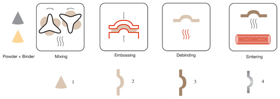
Figure 1.
Powder hot embossing technology flowchart.
It has been a challenge to develop a new technology, which is based on an already matured one applied for polymers [3] but practically non-existent for ceramic and metallic materials a decade ago (some examples for metal powder hot embossing are described in [5,6,7,8,9]). The powder hot embossing technology was developed by some correlations with µ-PIM, used until the last decade for the production of metallic parts with micro/nanofeatures [3,10]. Currently, additive manufacturing (AM) techniques, such as microselective laser melting or micrometal extrusion, can be an alternative way for producing micrometallic parts [11]. However, each technology has a specific field of application: powder hot embossing is suitable for producing small series of less complex geometries; µ-PIM is used for large series production of small pieces with complex shapes and features up to submillimeter scale; AM technology can be used when the required geometries are impossible to produce by PIM or when a customization part is needed (single-part production).
All technologies have advantages and limitations that must be considered when they are applied for developing a part/component/product. Powder hot embossing has the same advantages as polymeric hot embossing, namely cost-effectiveness for small and medium series, flexibility in material choice, reproducibility and rapid development of complex shapes [7,8,12].
The final products obtained by powder hot embossing technology are, until now, microengineering applications, such as micromold inserts or micromedical components [13,14,15]. The studies concerning the developments of powder hot embossing are summarized in this revision. They are presented in detail, considering the four stages of this technology and the characterization of the final parts.
2. Feedstock Preparation for Powder Hot Embossing
The production of feedstock is the first step of powder hot embossing process. A feedstock is a mixture of powder and binder, at a specific powder concentration, which enables the shaping of very small parts/components with rather complex configurations, as applied in the µ-PIM process. The purpose of a mixture, production of a feedstock, is to disperse the powder in the binder without internal porosity and agglomeration, that is, to obtain a homogeneous biphasic mixture of powders and polymeric binders, and each metallic particle should be covered with a thin layer of binder [16,17]. The characteristics of the feedstock are dependent on the powder and binder characteristics and on the mixing process. This section will discuss the input materials (powder and binder), the feedstock preparation techniques and the evaluation of feedstocks used for powder hot embossing.
2.1. Input Materials
The preparation of feedstocks is, as already mentioned, one of the most critical steps of this technology; a correct selection of binder, metallic powder and additives (surfactants and/or reinforcements). The use of appropriate proportions of the various constituents and the production of a homogeneous mixture are essential, which requires knowing the properties of the constituents used.
The metal powder is a fundamental constituent, it is present in all stages of the process and corresponds to the final material. The characteristics of the powder that influence the process of powder hot embossing (analogous to PIM and µ-PIM) are the particle size distribution (PSD), the morphology, the density, the specific surface area and the interaction between particles. All these characteristics determine the rheological behavior of the feedstock. The crystallographic structure, chemical composition and moisture content are also important aspects, critical for debinding and sintering. Some studies [17,18] pointed out the requirements that make powders suitable for these processes. Powders with small particles, compared to coarser ones, allow higher kinetics of sintering and facilitate the reproduction of details during shaping, however, they increase the viscosity of the mixture, agglomerate more easily and lead to prolonging the binder removal time. The typical size of the powders used for hot embossing is between 3 and 10 µm (Table 1). The morphology of powders used is mostly spherical. Spherical powder particles allow better shaping and the use of higher solid content on mixtures, however, powders with irregular geometries reduce the distortions that may occur during debinding process [17,18,19]. It is impossible to obtain a powder that has all the desirable requirements, so an adequate balance must be selected.

Table 1.
Composition and characteristics of the powders and binders used for powder hot embossing.
The binder material has a strong influence on the optimization of the parameters of mixing, embossing and debinding steps and consequently affects the properties and characteristics of the final parts. Currently, binders developed for µ-PIM are used for powder hot embossing. These binders are usually composed of a main part (known as backbone polymer that has the purpose of supporting and maintaining the shape of the components until the sintering stage), some additives such as waxes (used to decrease the viscosity of the feedstock) and surfactants (to increase the wettability of powder and binder) [31].
The binder should be partially and totally eliminated during the cycles of binder removal (debinding) and sintering, respectively. The procedures applied in these processes depend on the binder material and powder type. The binder can be partially removed either by the application of a dissolving or by a thermal process and then passed for a complete decomposition process (before heating to higher temperatures) combined with the sintering step [32,33]. This is called secondary debinding and sintering approach. However, a sequential debinding and sintering steps can be applied [20], or these treatments can be carried out separately in two different stages [13,29].
A binder system should be selected to fulfill several functions: to give adequate viscosity to the mixture in order to replicate the microdetails during the embossing process, to allow high resistance in the green state for better demolding and to allow good shape retention and low shrinkage during the debinding and sintering steps. The thermal properties of the binder system determine the temperatures used for mixing, embossing and debinding steps. The highest temperature that allows complete fusion of the binder system (determined by differential calorimetry (DSC)), without causing any decomposition of the binder materials (for which thermogravimetric analysis (TGA) was used), is selected for the mixing and embossing steps (known as critical temperatures). The TGA analysis is also used to determine the temperature required for a complete binder decomposition, which is useful for defining the parameters of the debinding process.
Table 1 lists materials used for powder hot embossing until now. Table 1 shows that the powder types used are still limited. The binder systems are also limited to some in-house binders (which are mostly based on polypropylene (PP), paraffin wax (PW) and stearic acid (SA)) and two commercial binder systems. Stainless steel SAE 316L powder is the most used metal powder, this may be due to the availability in the market of small particle size powders (D50 less than 10 µm) but also because this is the most used stainless-steel powder in PIM. The application of components made of stainless steel SAE 316L powder is diverse and involves different industrial sectors [10].
However, recent developments in AM powder technologies have expanded the diversity and availability of metal powders in the market. These powders have characteristics that are suitable to be used in powder hot embossing, increasing the opportunity for the applicability of this technology. Some authors [26] have conducted studies to make the PIM binder more suitable for powder hot embossing, using different formulations for the mixture of PP, PW and SA. The "design" of a suitable binder can be a crucial challenge for the hot embossing process, since until now, only commercial or in-house binders have been tested, with formulations that are typically used for the PIM process.
2.2. Preparation Techniques
In studies where in-house binders were used in the preparation of feedstocks, some were done with a single composition, while others evaluated the influence of different proportions of constituents to produce a more suitable feedstock (as shown in Table 2). These binders are typically composed of PP, PW and SA; the first constituent plays as the backbone polymer, the second one as a diluting agent and the last one as a surfactant.
Table 2.
Binders, production techniques using a torque mixing method, tests and characteristics of feedstocks used in powder hot embossing.
Table 2 also presents the rheological properties of some of the listed feedstocks. These properties were usually evaluated by plotting the shear viscosity versus shear rate, which showed a shear thinning behavior, and that the viscosity of these feedstocks was reduced by increasing the temperature (temperature sensitive behavior), as expected. Other authors (see, for example, [26]) performed the determination of the rheological characteristics using a capillary rheometer, similar to what is done in the µ-PIM (although the shaping step of the two technologies is different). Nevertheless, the influence of shear-viscosity does not seem to be as important for powder hot embossing as it is for µ-PIM since there is no application of torque during embossing. Besides, a complete filling of the mold can be achieved by applying the highest possible temperature, while avoiding the decomposition of the binder, otherwise, the filling of mold cavities is not completed.
In addition to critical temperatures, it is important to be able to determine the processing times to be used, such as the times for both mixing and holding during embossing. Some authors performed a DSC test at 180 °C and showed that degradation of binder occurred after 50 min of mixing, which limited the mixing time to be less than 50 min [23]. Table 2 also shows that the DSC and TGA analyses were performed to determine the processing temperatures of commercial binders. These binders showed a multistep melting and gradual decomposition behavior [14,20].
With the growing industrial importance of metal matrix composites, these advanced materials have also been processed by metal powder micromanufacturing processes. Recently, the addition of MWCNT (multiwalled carbon nanotubes) to aluminum and stainless feedstocks for powder hot embossing process has been reported [16]. MWCNTs were mixed with the powders before the preparation of the feedstock. This study aimed at evaluating the influence of carbon nanotubes on the feedstock and embossing step. Both the addition of nanomaterials and the use of a higher powder concentration thickened the feedstock, thus increasing the mixing torque values. This effect was attributed to the increased contact area between the added material and the binder, which consequently increased friction and resulted in higher energy required for mixing. The influence on the processing during the PIM technique of different reinforcements, such as titanium carbide and multiwalled carbon nanotubes (MWCNT), has also been reported (e.g., [35,36,37]). Finally, the application of nanoalumina mixed with SAE 316L stainless steel powder has been analyzed through the use of microsoft molding technique, which does not apply pressure and temperature during the embossing step [38].
The complete filling of the mold cavity details and the surface roughness of green parts depend on the powder concentration of the feedstock, known as powder loading (PL). This value presented in vol.%, is selected by evaluating the mixing torque behavior for various feedstocks with different powder concentration and then selecting the feedstock with the lowest torque homogenization value (e.g., Fe-8%Ni alloy in [14]), or by determining an absolute value called critical powder volume concentration (CPVC) [8] (also referred to by some authors as critical solid loading-CSL) [20]. For this critical value, the feedstock presents an infinite relative viscosity, which is defined as the viscosity of the feedstock in relation to the viscosity of the binder, and does not present fluidity [31,39]. Besides, the evolution of the mixing torque is influenced by mixing conditions and by feedstock composition. For example, the mixing torque values increase with raising mixing speed (up to 100 rpm) or with increasing powder or PP content [22,23]. In addition, the reduction of the mixing torque was correlated with adding SA, PW or with temperature increasing [16,22,23,26]. Table 3 summarizes the various approaches implemented to determine the CPVC and PL values during the powder hot embossing process. It has been defined that an optimized amount of powder corresponds to the selection of a slightly smaller PL value than the CPVC, and that this value can guarantee the replicability in the embossing process.
Table 3.
Determination of critical powder volume concentration (CPVC) reported in some studies related with powder hot embossing.
The value of the powder and binder content in feedstock (determined as PL) also affects the performance of debinding and sintering. An excess binder does not retain the shape after debinding [32]. Moreover, there is a minimum powder content that can ensure contact between the powders to create sintering necks between them, which leads to a final consolidation [40].
The determination of CPVC can be carried out through the techniques of torque rheometry or capillary rheometry. The first technique involves either thermal softening of the binder or oil absorption and the torque values. The torque values are obtained by a gradual powder addition procedure during mixing (Figure 2a) and are plotted against powder concentrations (Figure 2b). The CPVC is the volume for which the torque increases suddenly (for example, the value marked with the star in Figure 2b) [41,42,43]. In respect to the application of capillary rheometer, the flow activation energies are plotted against powder concentrations [44,45]. The CPVC is the one corresponding to the feedstock with less activation energy, which means lower viscosity sensitivity to temperature variations and, thus, a higher possibility of manufacturing defect-free parts. The capillary rheometry technique can involve the evaluation of other rheological properties, such as shear viscosity and shear rate [42,46,47].
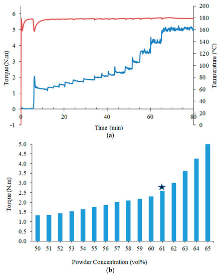
Figure 2.
Feedstock optimization of SAE 316L stainless steel powder mixed with a commercialized binder system at 180 °C and 30 rpm: (a) torque evolution against time, the red curve represents temperature and the blue curve represents torque evolution and (b) torque versus powder concentration.
The values of CPVC and PL are influenced by several factors, like the composition of binder [26,42,48], the PSD and the powder morphology [17,31,49,50]. Some authors have indicated that CPVC decreases with the decrease of PSD (due to the viscosity increase) and that it increases with the increase in sphericity of metallic particles [31]. These conclusions are not supported by the results of other authors who showed that it was not possible to establish a general trend (Table 4) [50].
Table 4.
Effect of particle size distribution (PSD) and atomization routes on the CPVC values [50].
This difficulty in generalizing trends was observed in other situations. For example, in the determination of CPVC using the binder thermal softening associated with gradually powder addition approach, a contradictory result was reported [26]. In this study, two in-house binders with different formulations were prepared, one with 70% (F1) and another with only 25% (F2) paraffin wax (F1 = 70%PP: 25%PW: 5%SA, F2 = 25%PP: 70%PW: 5%SA, presented in Table 2). F1 binder showed lower viscosity due to having a higher amount of paraffin wax, resulting in lower mixing torque values. As such, it was expected that this feedstock would show a higher CPCV, but the experimental values contradicted this trend (CPCV of 70% and 80% for F1 and F2, respectively; Table 3).
The homogeneity of the prepared feedstocks should be assessed to guarantee the production of a perfect part. The evaluation of this characteristic can be done through the analysis of the evolution of torque versus time during the preparation of the mixture, supported by scanning electron microscopy (SEM). This last technique shows that a well-prepared feedstock must have powders covered with a thin layer of binder (as illustrated in Figure 3) [51]. In the torque graph approach, it is assumed that the homogeneity of the feedstock is achieved when the torque variations reach a steady state, which is affected by the composition of the binder used [42,52], the speed and time of mixing and the powder concentration [23,51,53]. Homogeneity can also be evaluated by checking if the measured density of a feedstock sample is analogous to its theoretical density. The gas absorption technique can determine the density of the feedstock produced, which may be essential to determine whether different batches of the same feedstock have similar values [9,54].
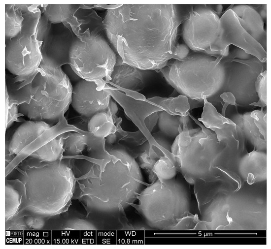
Figure 3.
Feedstock for powder hot embossing (316L powder and M1, commercial binder), SEM image.
3. Hot Embossing
Shaping a feedstock into a configuration replicating all the details/features is the main goal of this powder hot embossing step. This step is composed of four main stages, analogously to polymers hot embossing: (1) heating the mold and feedstock to embossing temperature, (2) shaping the green part/replicate features into feedstocks by applying pressure at embossing temperature for a specific time, (3) cooling the mold and green part and (4) demolding the green part [2].
In studies where powder hot embossing was analyzed, it was reported that replicability (shape retention and surface roughness) is affected by critical embossing parameters: pressure [8,13,14,27,30], temperature [6,8,14,20,22,23,24,30] and holding time [6,8,9,20,24]. The temperature should be high enough to promote pseudoplastic behavior in the mixture; the embossing temperature range is predicted by TGA analysis [8,14,16,24], as already mentioned. The pressure must be enough for the filling of the mold cavities to occur and thus ensure a good replicability of features. The temperature and pressure must be applied long enough to assure that all cavities of the mold are well embossed on the green part. These embossing parameters depend on the characteristics of the feedstocks that have an influence on green parts replicability, mostly the feedstock viscosity, the binder thermal behavior and the powder size distribution.
The effect of adding carbon nanotubes to the feedstock was analyzed [16], and it was reported that this nanometric reinforcement did not affect replicability. However, the feedstock with MWCNT was thicker, requiring higher torque energy for mixing. Besides, carbon nanotubes have opposite effects because they increase both the homogeneity and surface roughness of green parts. Nevertheless, other factors may affect the embossing critical parameters: type of geometries/features, mass of the green part and mold material.
After ensuring the replicability of the component, one of the most critical factors during powder hot embossing is to demold the green parts without damaging or breaking them. The demolding step is affected by the critical parameters of the embossing: pressure and temperature. Increased pressure induces higher compressive forces between the green part and the mold. Higher temperatures lead to more significant differences in shrinkage between the mold and the green part (due to differences in thermal expansion coefficients) during cooling. High pressures should be avoided due to the risk of unsuccessful demolding: broken green parts and the presence of cracks (Figure 4). Demolding at a higher temperature than the room temperature can be useful as it reduces the stress between the green part and the mold due to differences in shrinkage, which helps to release the green parts.
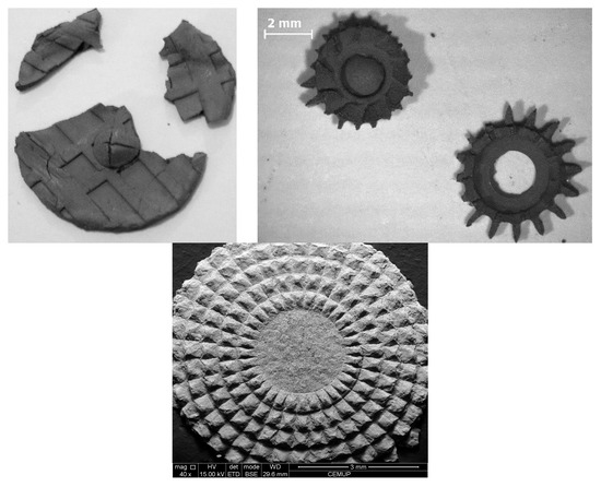
Figure 4.
Images of broken or damaged green parts after the embossing step.
The composition and design of the mold used for the embossing play a vital role in a successful demolding, considering the aspect ratio and geometry of the details/features to be replicated. During the last decade, different materials have been tested for the mold: from metallic to various elastomers. Figure 5 shows examples of some molds used. As the embossing temperature of the feedstocks was low (between 100 and 240 °C) and the series produced were small, elastomers could be used in the mold design. These materials have proved to be a solution for the demolding stage, allowing the release of green parts with guarantee. In fact, the release stage can be improved using these softer molds, as reported in [27], where different geometries and materials were tested. The use of release agents, which enhances the release stage, has been reported [13,34] even when elastomeric molds are used. These agents have the purpose of controlling or eliminating the adherence between the green parts and the mold.
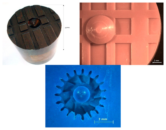
Figure 5.
Images of molds used in powder hot embossing.
The studies concerning powder hot embossing technology used either several feedstocks and mold materials, or tested different critical embossing parameters, or even crossing studies replicated diverse parts/components. Regardless, one study [27] examined more than one component (gear, tensile sample and parts with microdetails) and it showed that the geometry, dimensions, aspect ratio and distribution of the components in the mold affect the process, especially the hot embossing step. The critical parameters should be adjusted when changing one of these aspects, even if the same feedstock is used.
4. Debinding and Sintering
After embossing the green parts/components, they are densified by debinding and sintering treatments. Debinding can be performed through the application of different approaches, including solvent debinding, catalytic treatment, thermal treatment or a combination of these [18]. The debinding is performed to remove the binder materials slowly to retain the configuration of the shaped component, otherwise, it may cause defects such as cracks or fissures. The debound parts, called brown parts, proceed to the sintering treatment, which is vital in powder hot embossing and any other similar method such as PIM. The brown parts are very fragile, and cautious handling is needed because the main polymer has been removed in the last steps of the debinding process, and the metallic powder particles are only tenuously connected [18]. This step also leads to a roughness increase, as the interfacial distance between particles has not yet been removed [14].
In powder hot embossing, the application of thermal debinding has been the most reported method (Table 5). This treatment involves soaking the green parts in an oven with a flux of a controlled atmosphere. The binder materials are gradually decomposed and left the component in the gaseous state. This removal is gradual, occurring in several stages that are selected based on the results obtained by the TGA and DSC tests, as mentioned above. For example, some authors evaluated the stages at which an in-house made binder decomposed and showed that it presented a multistep decomposition due to the specific regime of decomposition of its various constituents [14,20]. A related study compared the influence of the type of the atmosphere (nitrogen, argon and high vacuum) on the debinding process, suggesting the occurrence of thermo-oxidation for debinding in the presence of the two gases [23]. Another study showed that a green part made of higher binder content did not retain the shape after thermal debinding [26].
Table 5.
Debinding processes applied to powder hot embossing.
As can be seen in Figure 6, the degradation of the binder material started at 230 °C, accelerated at 300 °C and ended at 500 °C. However, the slope of the weight loss curve changed at 400 °C and 450 °C. Therefore, the debinding procedure should include stages at all these temperatures, with certain holding times, to allow perfect decomposition.
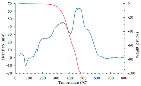
Figure 6.
Combination of TGA and DSC results obtained by the application of a heating rate of 10 °C/min in Ar atmosphere for a commercial binder material (M1) (adapted from [16]), the red curve represents the weight loss and the blue curve represents the heat flux.
Table 6 presents the conditions and main achievements reported in the sintering process of powder hot embossing. Most studies have applied a temperature well above half of the melting point of the powder for one hour in vacuum atmosphere.
Table 6.
Achievements related to sintered parts by the powder hot embossing process.
Some authors [14] have not detected any damage caused by the application of a rather high heating rate (15 °C /min). Besides, they reported that the higher the temperature, the greater the densification, due to the influence of higher diffusion; and that the higher the powder concentration, the lower the shrinkage, which is attributed to a higher density of the green parts. The use of a less viscous feedstock can provide a better filling for the embossing step. Still, this type of feedstock is very sensitive to debinding and sintering temperatures, and the part can lose its shape [23]. It is also essential to avoid the occurrence of liquid phase sintering to retain the shape of microscale aspects. In Table 6, it is shown that most studies have been dedicated to SAE 316L stainless steel and some to copper, Co-WC and Fe-Ni tool steel. The occurrence of isotropic shrinkage has only been reported for the copper components [7,20]. It should be noted that no study has reported the sintering of Al parts produced by powder hot embossing. It is also reported that the surface roughness depends on the sintering temperature, for example, the roughness decreased for sintered copper when the temperature rises from 750 to 950 °C but increased when sintering was performed at 1000 °C [20]. The decrease was attributed to the elimination of superficial pores, while the roughness increase may have been caused by the influence of grain growth or the flow of material at high temperatures. Surface roughness as small as that of the master mold was reported for 316L stainless steel part using a powder with a D50 of 3.5 µm [29].
5. Final Parts
The first evaluation of the final parts is to verify the shape form retention or the replicability of the details/features on the sintered part and compare them with the mold. This evaluation has been done in all studies reported in the literature for powder hot embossing. Shape retention, dimensions and shrinkage are related characteristics commonly accessed in sintered parts/components. Some of these achievements were already mentioned in Table 6, where results after sintering are reported: density, porosity, surface quality (surface roughness and replicability evaluation), shrinkage and hardness. However, these achievements in the final parts/components do not depend only on the sintering step, as already stated, and will be analyzed in more detail at this point.
The surface quality of the final parts is an important issue in the microcomponents as it affects its performance in service. This surface quality is an excellent example of a characteristic that is affected by all the steps of the powder hot embossing process. It is affected by the surface of green parts, which in turn are affected by the characteristics of the selected materials and feedstocks, by the critical embossing parameters (temperature, pressure and time), and by mold materials and their surface finishing quality (as mentioned before when addressing the embossing step). For example, surface roughness is influenced by the PSD of the powder: by using a finer powder surface quality is improved [55] and the roughness is reduced (Ra) [23]. Although the PSD of the selected powder has a stronger influence on roughness, parameters such as feedstocks characteristics, the mold used in the embossing step and the sintering temperature can have a significant impact [20,23,26,55]. Regarding the influence of feedstock characteristics, some authors [26] observed that the surface roughness of metallic parts made with a less viscous feedstock is much lower than that of those made with a more viscous feedstock. Other authors [29] used a feedstock reinforced with MWCNT and concluded that a part made with this feedstock had surface characteristics closer to the mold employed during the embossing step than that produced with the same feedstock without the nanotubes.
The density of the final parts produced by powder hot embossing ranged from 93% [20] to 98.2% [56]. This density strongly depends on a good practice of debinding and sintering, being also dependent on different parameters such as powder loading. It has been demonstrated that the density has increased significantly (from 96% to 97.8%) with the increase in sintering temperature (1200–1360 °C) in samples produced with a SAE 316L stainless steel feedstock [23]. Another study [56] analyzed the effect of different powder loadings (PL of 60, 62 and 64 vol.%) and showed that feedstocks with higher power loadings lead to parts with higher density. In the same study, it was also demonstrated that sintering kinetics affects the density of the final parts since higher kinetics, caused by the thermal shock resulting from a higher heating rate, decreases porosity faster and, in turn, increases density. The percentage of porosity measured in the final parts can vary between 3% [24] and 10% [13] and is also influenced by the pressure of the embossing step. The increase of the embossing pressure (from 4 to 28 MPa) in a SAE 316L stainless steel part decreased the porosity from 10% to 4%, measured by mercury porosimetry [13]. The knowledge of the influence of several factors on porosity allows controlling this characteristic and producing porous components, with an internal network of interconnected pores, but with structural integrity, and with industrial application in the production of metallic microneedles [15].
The mechanical properties and internal structure of the final parts are interrelated and dependent on the metal powder used. They are strongly affected by all process parameters and their analysis is essential for the optimization of the powder hot embossing process. In a study, the effect of the embossing pressure on the microstructure and hardness of 316L steel parts was analyzed [13]. The microstructure consists of equiaxed austenite grains with twins (regardless of embossing pressure). Still, on the part with higher pressure, the porosity is lower and less visible, which agrees with the highest hardness value (157 ± 7 HV 0.01) measured on the parts tested. The microstructures of powder hot embossed parts are analogous and comparable to those reported in the literature in the PIM process, for the same powder material [8]. As an example, Figure 7 shows a microstructure of a SAE 316L stainless steel final part produced by powder hot embossing.
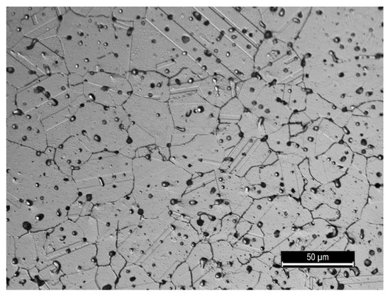
Figure 7.
Microstructure of a SAE 316L stainless steel final part produced by powder hot embossing: austenite grains with visible porous.
Functional tests are essential to predict the functionality of the component in service and are application dependent. For example, the feasibility of applying metallic microneedles produced as a scalable platform for biosensing and drug administration has been tested by performing skin insertion analysis, dry drug elution and in vitro permeability [15]. The results reported that microneedles could store a dehydrated drug, insert it into the skin and elute out the drug, showing advantages in its use in comparison to traditional hypodermic needles.
The diversity of applications produced by powder hot embossing has the potential to become more and more significant, particularly for low-cost medium series of microparts/components. Several feedstocks were processed by powder hot embossing, which successfully produced parts with different applications, such as: insert molds with microdetails (for injection molding of polymers for the automotive industry and microfluidic components) or microneedles (for drug delivery and biosensing) [15,22,34]. Molds with microdetails for microscale applications of injection molding of plastic parts, as headlights (light-emitting diode-LED) for a vehicle (Figure 8), is an example of the importance of powder hot embossing. A disposable mold-inserts to produce by injection polymethyl methacrylate (PMMA) microparts, becomes an economical and sustainable solution. The possibility of changing only those inserts that show significant wear during manufacturing, instead of machining the entire mold, is a competitive advantage for the molding industry. The production and process optimization of disposable mold-inserts was a significant part of the ToolingEDGE project (7th Framework Program), which contributed to reinforce the importance of the Portuguese Engineering Molding Industry.
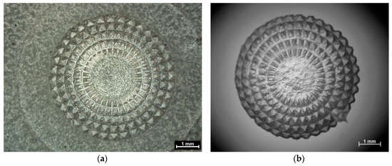
Figure 8.
Image of disposable mold-insert produced by powder hot embossing (a) and the injected LED PMMA micropart (b).
6. Conclusions
Powder hot embossing is a newly developed method for micromanufacturing metallic parts at a low cost. The application of powders in the range of 3.5–10.0 µm, in-house and commercial binder systems, and elastomeric matrices has been reported. The characterization of input materials, more specifically the feedstock, has been emphasized because the shaping is achieved by applying pressure to a viscous material allowing the filling of microdetails in low-cost molds. The replicability and surface quality are influenced by the characteristics of the powder, binder composition, mold material and critical processing conditions (temperature, pressure and holding time). The performance of the thermal debinding process has been the most applied approach to selecting parts for the sintering step. Although shrinkage and final density depend on the sintering temperature, the characteristics of the powder, the embossing pressure and the heating rate are also important parameters. Recent developments of new powders, associated with the development of additive manufacturing, and new binders, can improve feedstocks and consequently, the reproducibility of green parts and final properties, leading the technology to a more mature stage with more significant market implementation.
Author Contributions
All authors contributed to the conceptualization, writing and revision of the manuscript. E.W.S. and O.E. also contributed with experimental data presented in this work. All authors have read and agreed to the published version of the manuscript.
Funding
This research received no external funding.
Acknowledgments
The authors would like to express thanks to CEMMPRE (Centre for Mechanical Engineering, Materials and Processes) for the support granted and CEMUP (Centro de Materiais da Universidade do Porto) for assistance with SEM.
Conflicts of Interest
The authors declare no conflict of interest.
References
- Hernandez, P.; Campos, D.; Socorro, P.; Benitez, A.; Ortega, F.; Diaz, N.; Marrero, M.D. Electroforming applied to manufacturing of microcomponents. In Mesic Manufacturing Engineering Society International Conference 2015; Canela, J.M., Corral, I.B., Eds.; Elsevier Ltd.: Amsterdam, The Netherlands, 2015; Volume 132, pp. 655–662. [Google Scholar]
- Worgull, M. Hot Embossing-Theory and Technologie of Microreplication; William Andrew: Qxford, UK, 2009. [Google Scholar]
- Kuduva-Raman-Thanumoorthy, R.; Yao, D. Hot embossing of discrete microparts. Polym. Eng. Sci. 2009, 49, 1894–1901. [Google Scholar] [CrossRef]
- Khan Malek, C.; Coudevylle, J.R.; Jeannot, J.C.; Duffait, R. Revisiting micro hot-embossing with moulds in non-conventional materials. Microsyst. Technol. 2006, 13, 475–481. [Google Scholar] [CrossRef]
- Rota, A.; Duong, T.V.; Hartwig, T. Micro powder metallurgy for the replicative production of metallic microstructures. Microsyst. Technol. 2002, 8, 323–325. [Google Scholar] [CrossRef]
- Fu, G.; Tor, S.; Loh, N.; Hardt, D. Micro-hot-embossing of 316L stainless steel micro-structures. Appl. Phys. A: Mater. Sci. Process. 2009, 97, 925–931. [Google Scholar] [CrossRef]
- Sahli, M.; Millot, C.; Gelin, J.C.; Barrière, T. Development and characterization of polymers-metallic hot embossing process for manufacturing metallic micro-parts. AIP Conf. Proc. 2011, 315, 677–682. [Google Scholar] [CrossRef]
- Sequeiros, E.W.; Ferreira, T.J.; Vieira, M.T.; Vieira, M.F. Study and development of micro hot embossing on 316L/polymer mixtures. In Proceedings of the Euro PM 2011, Barcelona, Spain, 9–12 October 2011. [Google Scholar]
- Emadinia, O.; Sequeiros, E.W.; Vieira, M.T.; Vieira, M.F. Hot-embossing micro parts made of aluminium and aluminium reinforced with carbon nanotube: feedstock preparation and shaping. In Proceedings of the WorldPM, Hamburg, Germany, 9–13 October 2016. [Google Scholar]
- German, R.M. 1-Metal powder injection molding (MIM): key trends and markets. In Handbook of Metal Injection Molding; Woodhead Publishing: Cambridge, UK, 2012; pp. 1–25. [Google Scholar] [CrossRef]
- Nagarajan, B.; Hu, Z.H.; Song, X.; Zhai, W.; Wei, J. Development of Micro Selective Laser Melting: The State of the Art and Future Perspectives. Engineering 2019, 5, 702–720. [Google Scholar] [CrossRef]
- Razali, A.R.; Qin, Y. A Review on Micro-manufacturing, Micro-forming and their Key Issues. In Malaysian Technical Universities Conference on Engineering & Technology 2012; Aljunid, S.A., Anuar, M.S., Salimi, M.N., Ismail, K.A., Eds.; Elsevier Ltd.: Amsterdam, The Netherlands, 2013; Volume 53, pp. 665–672. [Google Scholar]
- Sequeiros, E.W.; Neto, V.C.; Vieira, M.T.; Vieira, M.F. Hot micro-embossing: effect of pressure on 316L metal parts. Powder Metall. 2014, 57, 241–244. [Google Scholar] [CrossRef]
- Sahli, M.; Gelin, J.C.; Barriere, T. Characterisation and replication of metallic micro-fluidic devices using three different powders processed by hot embossing. Powder Technol. 2013, 246, 284–302. [Google Scholar] [CrossRef]
- Cahill, E.M.; Keaveney, S.; Stuettgen, V.; Eberts, P.; Ramos-Luna, P.; Zhang, N.; Dangol, M.; O’Cearbhaill, E.D. Metallic microneedles with interconnected porosity: A scalable platform for biosensing and drug delivery. Acta Biomater. 2018, 80, 401–411. [Google Scholar] [CrossRef]
- Emadinia, O.; Vieira, M.T.; Vieira, M.F. Feedstocks of Aluminum and 316L Stainless Steel Powders for Micro Hot Embossing. Metals 2018, 8, 999. [Google Scholar] [CrossRef]
- Sotomayor, M.; Várez, A.; Levenfeld, B. Influence of powder particle size distribution on rheological properties of 316L powder injection moulding feedstocks. Powder Technol. 2010, 200, 30–36. [Google Scholar] [CrossRef]
- Banerjee, S.; Joens, C.J. 7-Debinding and sintering of metal injection molding (MIM) components. In Handbook of Metal Injection Molding; Woodhead Publishing: Cambridge, UK, 2012; pp. 133–180. [Google Scholar] [CrossRef]
- Jorge, H.R.S. Compounding and Processing of a Water Soluble Binder for Powder Injection Moulding. Ph.D. Thesis, Universidade do Minho, Campus de Azurém-Guimarães, Portugal, November 2008. [Google Scholar]
- Sahli, M.; Millot, C.; Gelin, J.C.; Barrière, T. The manufacturing and replication of microfluidic mould inserts by the hot embossing process. J. Mater. Process. Technol. 2013, 213, 913–925. [Google Scholar] [CrossRef]
- Rota, A.; Duong, T.V.; Hartwig, T. Wear resistant tools for reproduction technologies produced by micro powder metallurgy. Microsyst. Technol. 2002, 7, 225–228. [Google Scholar] [CrossRef]
- Zhang, J.; Gelin, J.C.; Sahli, M.; Barrière, T. Manufacturing of 316L Stainless Steel Die Mold by Hot Embossing Process for Microfluidic Applications. J. Micro Nano-Manuf. 2013, 1, 041003. [Google Scholar] [CrossRef]
- Zhang, J.; Sahli, M.; Gelin, J.C.; Barriere, T. Rapid replication of metal microstructures using micro-powder hot embossing process. Int. J. Adv. Manuf. Technol. 2015, 77, 2135–2149. [Google Scholar] [CrossRef]
- Sequeiros, E.W.; Ferreira, T.J.; Neto, V.C.; Vieira, M.T.; Vieira, M.F. Micro metal powder hot embossing: A new route to produce micro metallic parts. In Proceedings of the International Euro Powder Metallurgy Congress and Exhibition, Euro PM 2014, Salzburg, Austria, 21–24 September 2014. [Google Scholar]
- Sequeiros, E.W.; Santos, R.F.; Vieira, M.T.; Vieira, M.F. Impact of Binder on AISI 316L Microcomponents Produced by Hot Embossing: SEM/EBSD Analysis. Microsc. Microanal. 2016, 22, 50–51. [Google Scholar] [CrossRef][Green Version]
- Sahli, M.; Gelin, J.C. Development of a feedstock formulation based on polypropylene for micro-powder soft embossing process of 316L stainless steel micro-channel part. Int. J. Adv. Manuf. Technol. 2013, 69, 2139–2148. [Google Scholar] [CrossRef]
- Sequeiros, E.W.; Vieira, M.T.; Vieira, M.F. Hot embossing: Effect of parameters process on replicated 316l metal structures. In Proceedings of the International Euro Powder Metallurgy Congress and Exhibition, Euro PM 2012, Basel, Switzerland, 16–19 September 2012. [Google Scholar]
- Sequeiros, E.W.; Ferreira, T.J.; Neto, V.C.; Vieira, M.T.; Vieira, M.F. Microstructural Characterization of Metallic Parts Produced by Hot Embossing. Microsc. Microanal. 2015, 21, 49–50. [Google Scholar] [CrossRef]
- Emadinia, O.; Vieira, M.T.; Vieira, M.F. Micro Hot-embossing AISI 316L Reinforced with Carbon Nanotubes. In Proceedings of the International Euro Powder Metallurgy Congress and Exhibition, Euro PM 2017, Milan, Italy, 1–5 October 2017. [Google Scholar]
- Sahli, M.; Gelin, J.C.; Barriere, T. Replication of microchannel structures in WC-Co feedstock using elastomeric replica moulds by hot embossing process. Mater. Sci. Eng. C-Mater. Biol. Appl. 2015, 55, 252–266. [Google Scholar] [CrossRef]
- Enneti, R.K.; Onbattuvelli, V.P.; Atre, S.V. 4-Powder binder formulation and compound manufacture in metal injection molding (MIM). In Handbook of Metal Injection Molding; Woodhead Publishing: Cambridge, UK, 2012; pp. 64–92. [Google Scholar] [CrossRef]
- Barreiros, F.M.; Vieira, M.T.; Castanho, J.M. Fine tuning injection feedstock by nano coating SS powder. Met. Powder Rep. 2009, 64, 18–21. [Google Scholar] [CrossRef]
- Abolhasani, H.; Muhamad, N. A new starch-based binder for metal injection molding. J. Mater. Process. Technol. 2010, 210, 961–968. [Google Scholar] [CrossRef]
- Sequeiros, E.W.; Vieira, M.T.; Vieira, M.F. Micro Hot Embossing of Metallic Powder as a Route to Manufacture Steel Mould-Inserts-In Search of Optimizing Process Parameters. In Proceedings of the International Euro Powder Metallurgy Congress and Exhibition, Euro PM 2017, Milan, Italy, 1–5 October 2017. [Google Scholar]
- Ferreira, T.J.; Vieira, M.T. Optimization of MWCNT-Metal Matrix Composites feedstocks. Cienc. Tecnol. Mater. 2017, 29, e87–e91. [Google Scholar] [CrossRef]
- Khakbiz, M.; Simchi, A.; Bagheri, R. Investigation of rheological behaviour of 316L stainless steel-3 wt-%TiC powder injection moulding feedstock. Powder Metall. 2005, 48, 144–150. [Google Scholar] [CrossRef]
- Ye, H.Z.; Liu, X.Y.; Hong, H.P. Fabrication of metal matrix composites by metal injection molding-A review. J. Mater. Process. Technol. 2008, 200, 12–24. [Google Scholar] [CrossRef]
- Imbaby, M.F.; Jiang, K. Fabrication of free standing 316-L stainless steel-Al2O3 composite micro machine parts by soft moulding. Acta Mater. 2009, 57, 4751–4757. [Google Scholar] [CrossRef]
- Heaney, D.F. 3 - Powders for metal injection molding (MIM). In Handbook of Metal Injection Molding; Woodhead Publishing: Cambridge, UK, 2012; pp. 50–63. [Google Scholar]
- Quinard, C. Expérimentation, Modelisation et Simulation Dans le Domaine de L’éLaboration de Micro-composants Injectés à Partir de Poudres. Ph.D. Thesis, UFR Des Sciences et Techniques de L’Université de Franche-Comté, Besançon, France, 3 December 2008. [Google Scholar]
- Barreiros, F.M.; Vieira, M.T. PIM of non-conventional particles. Ceram. Int. 2006, 32, 297–302. [Google Scholar] [CrossRef]
- Kong, X.; Quinard, C.; Barrière, T.; Gelin, J.-C. Mixing and Characterisation of stainless steel 316L feedstock. Int. J. Mater. Form. 2009, 2, 709–712. [Google Scholar] [CrossRef]
- Abdoos, H.; Khorsand, H.; Yousefi, A.A. Torque rheometry and rheological analysis of powder–polymer mixture for aluminum powder injection molding. Iran. Polym. J. 2014, 23, 745–755. [Google Scholar] [CrossRef]
- Contreras, J.M.; Jimenez-Morales, A.; Torralba, J.M. Experimental and theoretical methods for optimal solids loading calculation in MIM feedstocks fabricated from powders with different particle characteristics. Powder Metall. 2010, 53, 34–40. [Google Scholar] [CrossRef]
- Ghanbari, A.; Alizadeh, M.; Ghasemi, E.; Rad, R.Y.; Ghaffari, S. Preparation of optimal feedstock for low-pressure injection molding of Al/SiC nanocomposite. Sci. Eng. Compos. Mater. 2015, 22, 549–554. [Google Scholar] [CrossRef]
- Reddy, J.J.; Ravi, N.; Vijayakumar, M. A simple model for viscosity of powder injection moulding mixes with binder content above powder critical binder volume concentration. J. Eur. Ceram. Soc. 2000, 20, 2183–2190. [Google Scholar] [CrossRef]
- Li, Y.M.M.; Li, L.J.J.; Khalil, K.A. Effect of powder loading on metal injection molding stainless steels. J. Mater. Process. Technol. 2007, 183, 432–439. [Google Scholar] [CrossRef]
- Ahn, S.; Park, S.J.; Lee, S.; Atre, S.V.; German, R.M. Effect of powders and binders on material properties and molding parameters in iron and stainless steel powder injection molding process. Powder Technol. 2009, 193, 162–169. [Google Scholar] [CrossRef]
- Park, S.-J.; Wu, Y.; Heaney, D.F.; Zou, X.; Gai, G.; German, R.M. Rheological and thermal debinding behaviors in titanium powder injection molding. Metall. Mater. Trans. A 2009, 40, 215–222. [Google Scholar] [CrossRef]
- Hausnerova, B.; Mukund, B.N.; Sanetrnik, D. Rheological properties of gas and water atomized 17-4PH stainless steel MIM feedstocks: Effect of powder shape and size. Powder Technol. 2017, 312, 152–158. [Google Scholar] [CrossRef]
- Liu, L.; Loh, N.H.; Tay, B.Y.; Tor, S.B.; Murakoshi, Y.; Maeda, R. Mixing and characterisation of 316L stainless steel feedstock for micro powder injection molding. Mater. Charact. 2005, 54, 230–238. [Google Scholar] [CrossRef]
- Kong, X.; Barriere, T.; Gelin, J. Determination of critical and optimal powder loadings for 316L fine stainless steel feedstocks for micro-powder injection molding. J. Mater. Process. Technol. 2012, 212, 2173–2182. [Google Scholar] [CrossRef]
- Supati, R.; Loh, N.; Khor, K.; Tor, S. Mixing and characterization of feedstock for powder injection molding. Mater. Lett. 2000, 46, 109–114. [Google Scholar] [CrossRef]
- Barreiros, F.M.; Vieira, M.T. Structural phase evolution with temperature of non-conventional particles in PIM. J. Mater. Process. Technol. 2008, 199, 425–430. [Google Scholar] [CrossRef][Green Version]
- Sequeiros, E.W. Microfabricação de Componentes Metálicos por Microgravação. Ph.D. Thesis, Faculdade de Engenharia, Universidade do Porto, Porto, Portugal, 10 Jully 2014. [Google Scholar]
- Sahli, M.; Mamen, B.; Ou, H.; Gelin, J.C.; Barriere, T.; Assoul, M. Experimental analysis and numerical simulation of sintered micro-fluidic devices using powder hot embossing process. Int. J. Adv. Manuf. Technol. 2018, 99, 1141–1154. [Google Scholar] [CrossRef]
© 2020 by the authors. Licensee MDPI, Basel, Switzerland. This article is an open access article distributed under the terms and conditions of the Creative Commons Attribution (CC BY) license (http://creativecommons.org/licenses/by/4.0/).