Microstructure and Mechanical Properties of M50 Steel by Combining Cold Rolling with Austempering


1
School of Materials Science and Engineering, Wuhan University of Technology, Wuhan 430070, China
2
Hubei Key Laboratory of Advanced Technology for Automotive Components, Wuhan 430070, China
3
Hubei Engineering Research Center for Green Precision Material Forming, Wuhan 430070, China
4
School of Logistics Engineering, Wuhan University of Technology, Wuhan 430070, China
*
Author to whom correspondence should be addressed.
Metals 2020, 10(3), 381; https://doi.org/10.3390/met10030381
Submission received: 21 February 2020
/
Revised: 13 March 2020
/
Accepted: 14 March 2020
/
Published: 16 March 2020
1. Introduction
M50 steel is widely used in the manufacture of high-end bearing steel for aeroengine shafts in the aerospace industry [1,2,3]. Compared with the most common GCr15 low alloy steel, M50 steel grade is a high alloy steel that relies on tempering to achieve secondary strengthening [4]. It is routinely treated by a martensitic quenched and tempered heat treatment to obtain the microstructure consisting of dominant tempered martensite, a small amount of retained austenite (RA) and carbides [5]. These microstructures lead M50 steel to achieve excellent strength, hardness, and dimensional stability. However, compared with lower strength steels, the impact toughness of M50 steel is poor, which results in short service life and low reliability of bearings. Therefore, how to improve the impact toughness of M50 steel is a major issue that needs further attention.
It is well known that a martensite-bainite (M/B) duplex microstructure obtained by austempering in high strength steels exhibits superior toughness than the single martensite microstructure [6,7,8,9,10,11,12]. Wei et al. [13] believed that the M/B duplex microstructure obtained by austempering could improve the impact toughness of bearing steel compared with traditional martensite quenching-tempering (Q-T) heat treatment. Li et al. [14] reported that an excellent combination of strength and toughness could be obtained by combining pre-quenching with austempering. Moreover, the acquisition of partial lower bainite in bearing steels can improve the toughness of the material, and thus contribute to the rolling contact fatigue life of bearings [15]. In general, the studies above indicate that the M/B duplex microstructure can exhibit an excellent combination of strength and impact toughness in bearing steels. However, the applications of austempering to enhance the properties of interest are mainly concentrated on steels containing low/ultra-low or medium carbon and low alloy [16]. Only a few applications related to the austempering process in secondary hardening steels have been reported. Therefore, more importance should be attached to further improving the mechanical properties of secondary hardening steels by austempering.
Generally, prior to the Q-T treatment, bearing steels often need to be subjected to CR with the goal of the shape-forming of bearing workpieces [17]. The CR has been proven to improve the strength and toughness of bearing steels, owing to grain refinement [18,19], martensite refinement [20], bainite refinement, and solution strengthening [21]. Hence, the ultrafine M/B duplex microstructure with superior properties is hopefully obtained in M50 steel by combining CR with austempering. Chakraborty et al. believed that the impact toughness of bearing steels could be improved by austempering to obtain an M/B duplex microstructure compared with traditional Q-T. In addition, they further improved the impact toughness of the material through a judicious combination of CR and austempering, noting that it is mainly due to the refinement of the width of bainitic ferrite [22,23]. Beswick [24] reported that CR facilitated the transformation of ferrite to austenite and decreased the martensite start (Ms) temperature. Tsuji et al. [25] believed that combining CR with the phase transformation of steel had the potential to obtain a nano-scale microstructure, thus improving the mechanical properties of the material. By combining CR with austempering, Lu et al. tremendously improved the impact toughness of GCr15 steel, which was attributed to the formation of the nano-scale M/B duplex microstructure and thin-film of RA [26]. However, there are few reports concerning on the application of CR combined with austempering in M50 steel, and the effect of CR on the evolution of microstructure as well as the relationship between the microstructure evolution and the final mechanical properties are not clear.
In this paper, the effect of CR on the microstructure evolution and final mechanical properties of the austempered M50 steel are studied, and then, the relationship of the microstructure evolution on the final mechanical properties is discussed in detail.
2. Experiments and Methods
2.1. Specimen Preparation
The material used in the current study is M50 steel, with the chemical composition presented in Table 1. The investigated steel was supplied as a spheroidized annealed bar with a diameter of ϕ 30 mm, showing a microstructure consisting of carbides embedded in ferritic matrix. Specimens were machined into bars with dimensions of 13 mm × 14 mm × 200 mm by wire-electrode and subjected to oil quenching and the austempering process without and with CR, respectively. Then, all specimens were subjected to two types of heat treatment process, as shown in Figure 1.
The specimens for oil quenching process were austenitised at 1090 °C for 30 min, followed by quenching into oil (60 °C), which is illustrated in Figure 1a. Figure 1b depicts the schematic diagram of the austempering process without and with CR. The cold rolling experiment was conducted by using a twin-roller rolling machine, and a 20% thickness reduction ratio was applied with three passes. As for the austempering process, the specimens were austenitised at 1090 °C for 30 min in a vacuum furnace followed by austempered at 240 °C in a salt bath furnace for 1h and then oil quenched to room temperature. Triple tempering at 550 °C for 120 min was carried out for all the quenched specimens.
2.2. Microstructure Characterization
The microstructure of spheroidized experimental steels without and with CR was examined by electron backscatter diffraction technique (EBSD, OIG, Oxford, UK). The specimens for EBSD were mechanically polished and then subjected to Colloidal Silica (OPS) polishing. The microstructure of specimens subjected to Q-T and the austempering process were etched in 4% nital solution and then characterized by field emission scanning electron microscopy (FESEM, FEI, Hillsboro, OR, USA) at an acceleration voltage of 30 kV. The morphology and sub-plates of the different microstructures of tempered specimens were detected by transmission electron microscope using a JEOL-2100F microscope (TEM, JEOL, Akishima, Japan) operating at 200 kV. The TEM specimens were cut into disks with the thickness of 0.4 mm by wire cutting, mechanically ground down to 60 μm in thickness, and then thinned to perforation on a TenuPol-5 twin-jet electro-polishing device (Struers, Copenhagen, Denmark) using an electrolyte composed of 7% perchloric acid and 93% glacial acetic acid with a voltage of 40 V at room temperature. Dilatometric experiments were conducted on a DIL805A dilatometer (TA, New castle, UK). Cylindrical specimens with dimensions of ϕ 4 mm × 10 mm cut from the annealed specimens were prepared for the experiments. The diffraction peak data was obtained by Rigaku D/max-2500/PC X-ray diffractometer (XRD, Rigaku, Tokyo, Japan) equipped with Mo-kα radiation target at a scanning speed of 1°/min. The volume fraction of RA was determined using a direct comparison method [27]. The specimens for XRD experiments were finely ground and then polished.
2.3. Mechanical Properties Determination
The hardness of the tempered specimens subjected to Q-T and the austempering process was measured on a 200HRS-150 Rockwell hardness tester (IHTI, Laizhou, China), which was given as the average of five measurements for each specimen. Static tensile tests were conducted in accordance with the national standard GB 228-87 on an AG-IC universal material testing machine. The total length of specimens was 60 mm, and the gauge length was 15 mm. Tests were performed at a traverse velocity of 10−3 m/min. Three specimens were tested for each process and the average tensile values were recorded. Charpy impact tests were performed using standard Charpy unnotched specimens (5 mm × 10 mm × 55 mm, GB/T 229-2007) on a JBW-300CD drop hammer impact toughness tester (MTS, Jinan, China) at room temperature. Three specimens were tested in each process to obtain the average value and error bar. After the impact tests, the impact fracture morphology was observed by field emission scanning electron microscopy.
3. Results and Discussion
3.1. Dilatometric Analysis
Figure 2 depicts the dilation versus temperature curves for the experimental steel without and with CR. The Ms temperature of experimental steel without and with CR can be obtained at the cooling rate of 10 °C/s, which indicates a notable decrease from 184 °C to 174 °C after CR. It is known that more carbon will be dissolved in the high temperature austenite, due to the enhanced carbide dissolution by CR. Consequently, the higher carbon in austenite could contribute to the decrease of Ms temperature in the experimental steel with CR.
3.2. Microstructure Observation
The microstructure of spheroidized experimental steel without and with CR was characterized by SEM/EBSD, as demonstrated in Figure 3. In Figure 3a,b, the black lines indicate high angle boundaries (>15°) and the red fine lines represent low angle boundaries (<15°). The large angle grain boundary can be regarded as ferrite grain, while the small angle grain boundary is the formed sub-grain. Obviously, a large number of low angle boundaries are observed in the experimental steel with CR, whereas nearly no low angle boundaries can be detected in the experimental steel without CR. Figure 3c,d display the distribution of the misorientation angle. It is clear that the relative frequency of low angle boundaries increases significantly after CR. In addition, the Kernel Averaged Misorientation (KAM) maps were also employed to analyze the local stresses variations in crystal lattice of grains. More green and red regions presented in Figure 3f indicate that intense compression strains have been induced by CR in the crystal lattice of these ferrite grains. These strains may contribute to the formation of many sub-grains within the deformed ferrite grains, thereby increasing the density of low angle boundaries in the microstructure, as shown in Figure 3b. Owing to maintain the local equilibrium of carbon content at the ferrite-austenite interface, carbon atoms would diffuse from carbides towards the ferrite-austenite interface during the transformation of ferrite to austenite, which will contribute to the dissolution of carbides [28]. In addition, the presence of these low angle boundaries in the microstructure is favorable to facilitate the transformation of ferrite to austenite [29]. Thus, more carbon and other alloy elements can be dissolved in the austenite and then the Ms temperature is consequently decreased.
Figure 4 displays the SEM micrographs of the as-quenched specimens subjected to Q-T and austempering process. The typical microstructure obtained by the traditional Q-T process is illustrated in Figure 4a, which is comprised of dominant Martensite-Austenite (M/A) islands and a few undissolved carbides. Figure 4b,c shows the microstructure of austempered specimen without and with CR, respectively. Obviously, the microstructure consists of fine bainite, blocky M/A islands and undissolved carbides. Image pro plus software was used to measure the thickness of bainite sheaves and more than 10 different images for austempered specimen without and with CR were used. The results show that the average thickness decreased from 142 nm to 86 nm compared with that in the specimens without CR, indicating that CR can significantly refine the bainite sheaves. Furthermore, the EDS spectrum is displayed in Figure 4d,e to determine the type of carbides (marked with a blue letter in Figure 4a). It can be deduced that, consistent with our previous finding [4], the rod-like carbides that contain rich Mo are identified as M2C, while spheroidal carbides that contain rich V are identified as MC, demonstrating that there are mainly two types of carbides (MC and M2C) in the as-quenched specimens subjected to Q-T process. Moreover, due to the identical automatizations, MC and M2C will also be retained in austempered specimens.
There are two factors that play important roles in the refinement of bainite sheaves: high nucleation rate of bainitic ferrites and random orientation distribution of grain boundaries. Lange et al. studied the relationship between the nucleation rate of bainitic ferrite and CR by quantitative analysis [30]. Equation (1) expresses the ratio of the nucleation rate of a state with CR to that of the state without CR, which is shown as follow:
where Js is steady state nucleation rate of bainitic ferrite, Dapp and DL are apparent diffusivity and lattice diffusivity of carbon atoms, respectively. S represents the number of nucleation sites. The subscripts d and o denote states with and without CR, respectively. σχγ and ε are functions related to interfacial energy. ϕ represents free energy of driving force for nucleation. It should be noted that the increased density of dislocations by CR would facilitate the apparent diffusivity of carbon atoms and provide more nucleation sites, which will contribute to the increase in nucleation rate. In addition, a large number of defects will form in the lattice of the crystal and should be retained in the form of deformation storage energy (DSE) after CR. In this case, the DSE will be released due to the rearrangement and partial disappearance of defects, which contributes to a state of low energy in the deformed grains. Consequently, new interfaces or high misorientation angle boundaries could be formed and random orientation distribution would be achieved by the migration of grain boundaries, which will further retard coalescence of bainitic ferrite during austempering.
Figure 5 displays the XRD patterns of as-quenched specimens subjected to Q-T and austempering process. It should be noted that obvious RA peaks can be observed in the patterns. Meanwhile, two different types of carbide peaks (MC and M2C) can be observed in the Q-T and austempered specimen, which is consistent with the previous EDS results (Figure 4). However, the negligible carbide peaks in austempered specimen with CR has also verified that carbide dissolution is enhanced by CR, which is thus coincided with our previous researches [4]. Quantitative results indicate that the volume fraction of RA in Q-T and austempered specimen without and with CR are 17%, 20.1%, and 24.3%, respectively. This demonstrates that the volume fraction of RA is increased by CR for the austempered specimens. Meanwhile, the carbon content of RA (Cγ) during austempering was determined using the equation αγ = 3.578 + 0.033Cγ [31], where αγ is the austenite lattice parameter. It was interesting to find that the carbon content of RA in Q-T and austempered specimen without and with CR are 0.80 wt. %, 0.81 wt. %, and 0.84 wt. %, respectively, indicating that Cγ of austempered specimen with CR is increased. It is reported that more carbon could partition from over-saturated ferrite to RA in the formation of bainite [32]. Meanwhile, an increased content of chromium retained at ferrite-austenite interface due to enhanced carbides dissolution could significantly improve the activation energy of carbon diffusion at the interface. Thus, the partition process is preferably enhanced, which stabilizes the RA during austempering.
Figure 6 displays the SEM micrographs of the tempered specimens, where it can be seen that all specimens consist of ferrite and fine precipitated carbides after high temperature tempering. There are mainly two shapes of ferrite in the microstructure: blocky polygonal ferrite and fine equiaxed ferrite.
Figure 7 presents the XRD diffraction patterns of tempered specimens subjected to Q-T and austempering process. It is indicated that RA peaks almost disappeared in the specimens, which means that RA has been completely decomposed after three cycles of tempering. It should be noted that MC and M2C carbide peaks can be observed in the diffraction patterns. A higher intensity of carbide peaks exhibited in austempered specimen with CR mean that more MC and M2C dispersed in the tempered microstructure, which is favorable for the hardness and strength of the microstructure.
The TEM micrographs of the Q-T and austempered specimen with CR are shown in Figure 8. Figure 8a depicts the microstructure of Q-T specimen after quenching, which mainly consists of M and blocky RA. The duplex microstructure of austempered specimen with CR is demonstrated in Figure 8b, illustrating that many sub-plates interact with each other, whereas thin-film of RA is sandwiched between the sub-plates. It is also hard to distinguish bainite and martensite in the M/B duplex microstructure. After tempering, blocky polygonal ferrite and a small amount of precipitates are obtained in Figure 8c. However, a finer microstructure comprised of fine equiaxed ferrite can be obtained in Figure 8d, which illustrates that more fine precipitates disperse within the ferrite-ferrite interfaces.
In fact, fine carbides could not only precipitate with bainitic ferrite plates but also precipitated when accompanied by the decomposition of RA. It has been proposed that a high content of carbon in nano-scale RA increases the driving force for carbide precipitation during tempering, which was confirmed by the high energy X-ray diffraction testing [33]. Peet studied the precipitation behavior of carbides during tempering and found RA with carbon enrichment decomposed to intense carbide precipitation at lath boundaries, which would prevent the coarsening of the bainitic ferrite [34]. During the tempering, the nano-scale RA with high driving force for carbide precipitation at the plate interface would decompose carbides intensely. Meanwhile, some carbides could be formed due to the increased density of interfaces and decomposition of bainite. Therefore, more carbides will be present in tempered microstructure of austempered specimen with CR, which may contribute to the superior strength and hardness.
It is well known that bainite will transform into ferrite and at the same time carbides will precipitate along the lath boundaries during high temperature tempering. Thus, it could be deduced that finer equiaxed ferrite will form due to the decomposition of bainite. With the carbides precipitated along the ferrite-austenite interfaces and within the ferrite, the ferrite will maintain its shape and it is hard to coalesce into polygonal ferrite. Meanwhile, due to the decomposition of RA, a newly-formed thin-film of ferrite is sandwiched between these equiaxed ferrite, which is favorable to increase the interfaces for further enhancing carbides precipitation and at the same time release the stress surrounded by carbides along the interfaces.
3.3. Mechanical Properties
Mechanical properties of specimens subjected to Q-T and austempering process after tempering are illustrated in Figure 9. It is apparent that an austempered specimen with CR exhibits optimum strength and impact toughness. The Charpy impact absorbed energy exhibits 2.3 times of that in Q-T specimen and the ultimate tensile strength has been improved by 10% comparing with Q-T specimen. Figure 9c shows that the Q-T specimen exhibits the highest hardness, whereas a slight reduction can be found in austempered specimen without CR. The stress-strain curves are presented in Figure 9d. All curves present two stages of deformation in the specimens. At the initial stage of strain, an elastic deformation stage can be observed. Then, the specimen will undergo a plastic deformation stage with the increase of strain. An obvious necking phenomenon is not observed in these curves, indicating that all specimens present typical embrittle feature. The elongation of austempered specimen with CR and Q-T specimen can be measured by the tensile test analyzing software, which exhibits 2.8% and 1.5%, respectively. The differences in the elongation can be ascribed to the size and shape of ferrite in the tempered specimens. As has been mentioned forehead, there are a large amount of fine equiaxed ferrite formed in the austempered specimen with CR, which could show better plasticity than the polygonal ferrite. As a consequence, the plasticity of austempered specimen with CR has been improved.
The enhanced impact toughness is mainly due to fine equiaxed ferrite and many interfaces formed during multistep phase transformation, which could improve the energy required for fracture by making crack propagation follow tortuous paths. In addition, the improved strength should be mainly related to the presence of fine carbides. On one hand, thin-film of RA could be decomposed into small carbides during subsequent tempering. On the other hand, it has been proposed that the increased density of the phase interfaces after quenching would facilitate the diffusion of carbon [35], thus local carbon enrichment will be generated and trigger the precipitation of carbides during subsequent tempering [36]. Furthermore, the reduction in hardness may be ascribed to the decreased amount of martensite formed during quenching. However, an increasing trend in hardness is presented in austempered specimen with CR, which is mainly due to the precipitated carbides enhanced by CR.
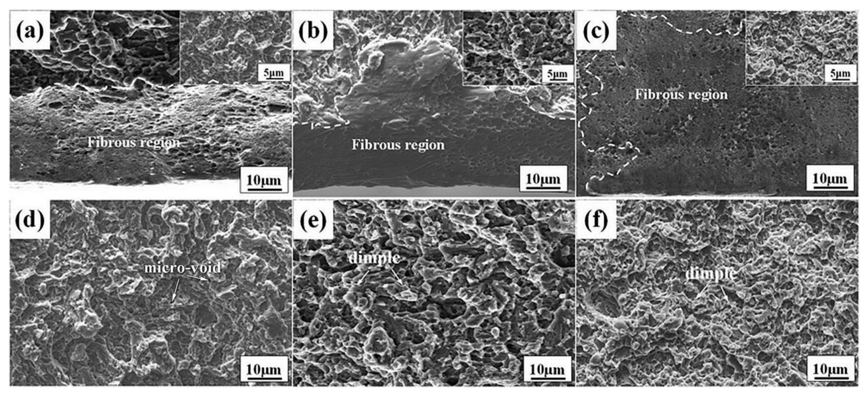
The impact fracture morphology of tempered specimens subjected to Q-T and austempering process was observed after impact test, as shown in Figure 10. The fracture morphology of Q-T and austempered specimen both exhibit obvious quasi-cleavage characteristics, and the cleavage facets consist of cleavage steps, tearing ridges and dimples. It is well pointed out that austempered specimen with CR shows more wider fibrous region than the Q-T specimen and austempered specimen without CR. Moreover, more smaller cleavage facets and uniform dimples can be also observed in the austempered specimen with CR, as indicated by Figure 10f.
Careful observation shows that fewer microvoids can be found in the austempered specimen with CR. It is generally believed that microvoids are the residual traces of the undissolved carbides that have fallen off during the fracture [37]. The presence of these micro-voids (marked in Figure 10d) indicates that some cracks nucleate at the interface between the undissolved carbides and martensitic matrix during the impact test. The strength of some martensite-carbide interface is relative smaller than martensitic matrix. Meanwhile, due to the coarsening of the carbides during tempering, the stress concentration will be increased at the interface, which leads to the nucleation of microcracks. Hence, it can be deduced that microcracks are susceptible to nucleation at the interface between larger-size carbides and ferrite matrix. Due to the excellent plasticity of bainitic ferrite, the stress at the carbide-ferrite interfaces will be released, which may hinder the nucleation of microcracks at the interface and thus improve the toughness.
4. Conclusions
In this work, the effect of CR on the microstructure evolution and final mechanical properties of the austempered M50 steel were investigated. The corresponding conclusions can be drawn:
- (1)
- The microstructural observation shows that CR refines the thickness of bainite sheaves, which would contribute to the formation of ultrafine equiaxed ferrite during subsequent tempering. Meanwhile, it is also found that more carbides precipitated within the ferrite and along ferrite-austenite interfaces.
- (2)
- The results of mechanical properties suggest that an excellent combination of ultimate tensile strength and impact toughness can be realized by combining CR with austempering. The ultimate tensile strength of austempered specimen with CR was increased by 10%, which is attributed to the increased precipitation in the austempered specimen with CR. The elongation of austempered specimen with CR is 2.8%, while that of Q-T specimen only reaches 1.5%. Furthermore, the impact absorbed energy at room temperature exhibited 2.3 times of that in Q-T specimen. The fracture analysis shows that more uniform dimples and wider fibrous regions can be found in the fracture of austempered specimen with CR.
Author Contributions
Conceptualization, D.Q. and X.L.; methodology, F.W. and Y.H.; software, Y.H.; validation, Y.C., D.Q. and F.W.; formal analysis, X.L.; investigation, Y.H.; resources, X.X.; data curation, F.W.; writing—original draft preparation, Y.H.; writing—review and editing, F.W.; supervision, Y.C.; project administration, D.Q.; funding acquisition, D.Q. All authors have read and agreed to the published version of the manuscript.
Funding
This research was funded by the National Natural Science Foundation of China, grant number 51875426, 51805390 and Important Science and Technology Innovation Program of HuBei province, grant number 2019AAA001 and Innovative Research Team Development Program of Ministry of Education of China, grant number IRT_17R83 and 111 Project, grant number B17034.
Conflicts of Interest
The authors declare no conflict of interest.
References
- Dodd, A.; Kinder, J.; Torp, B.; Nielsen, B.R.; Rangel, C.M.; da Svila, M.F. The effect of ion implantation on the fatigue life and corrosion resistance of M50 steel bearings. Surf. Coat. Technol. 1995, 74, 754–759. [Google Scholar] [CrossRef]
- Wang, F.; Qian, D.S.; Hua, L.; Mao, H.J.; Xie, L.C.; Song, X.D.; Dong, Z.H. Effect of high magnetic field on the microstructure evolution and mechanical properties of M50 bearing steel during tempering. Mater. Sci. Eng. A 2020, 771, 138623. [Google Scholar] [CrossRef]
- Bhadeshia, H.K.D.H. Steels for bearings. Prog. Mater. Sci. 2012, 57, 268–435. [Google Scholar] [CrossRef]
- Wang, F.; Qian, D.S.; Hua, L.; Lu, X.H. The effect of prior cold rolling on the carbide dissolution, precipitation and dry wear behaviors of M50 bearing steel. Tribol. Int. 2019, 132, 253–264. [Google Scholar] [CrossRef]
- Shen, W.Y.; Zhao, L.I.; Gong, J.X.; Li, G.Q.; Yuan, X. Heat treatment test of size stability for bearing ring of Cr4Mo4V steel. Heat. Treat. Technol. Equip. 2015, 36, 27–29. [Google Scholar]
- Zhao, J.; Wang, T.S.; Lv, B.; Zhang, F.C. Microstructures and mechanical properties of a modified high-C–Cr bearing steel with nano-scaled bainite. Mater. Sci. Eng. A 2015, 628, 327–331. [Google Scholar] [CrossRef]
- Gao, G.H.; Zhang, H.; Tan, Z.L.; Liu, W.B.; Bai, B.Z. A carbide-free bainite/martensite/austenite triplex steel with enhanced mechanical properties treated by a novel quenching-partitioning-tempering process. Mater. Sci. Eng. A 2013, 559, 165–169. [Google Scholar] [CrossRef]
- Dong, J.; Vetters, H.; Hoffmann, F.; Zoch, W.H. Microstructure and fatigue strength of the bearing steel 52100 after shortened bainitic treatment. J. ASTM. Int. 2010, 7, 2–10. [Google Scholar] [CrossRef]
- Garcia-Mateo, C.; Caballero, F.G.; Bhadeshia, H.K.D.H. Development of hard bainite. ISIJ Int. 2003, 43, 1238–1243. [Google Scholar] [CrossRef] [Green Version]
- Su, C.H.; Li, Q.G.; Huang, X.F.; Huang, W.G. Effect of bainite microstructure during two-step quenching and partitioning process on strength and toughness properties of a 0.3%C bainitic steel. J. Iron. Steel. Res. Int. 2018, 25, 235–242. [Google Scholar] [CrossRef]
- Sourmail, T.; Smanio, V. Optimisation of the mechanical properties of air cooled bainitic steel components through tailoring of the transformation kinetics. Mater. Sci. Eng. A 2013, 582, 257–261. [Google Scholar] [CrossRef]
- Gui, X.L.; Wang, K.K.; Gao, G.H.; Tan, Z.L.; Misra, R.D.K.; Bai, B.Z. Ultrahigh strength-toughness combination in Bainitic rail steel: The determining role of austenite stability during tempering. Mater. Sci. Eng. A 2016, 662, 162–168. [Google Scholar]
- Wei, D.Y.; Gu, J.L.; Fang, H.S.; Bai, B.Z. Fatigue behavior of 1500 MPa bainite + martensite duplex-phase high strength steel. Int. J. Fatigue 2004, 26, 437–442. [Google Scholar] [CrossRef]
- Li, C.; Wang, J.L. Effect of pre-quenching on martensite-bainitic microstructure and mechanical properties of GCr15 bearing steel. J. Mater. Sci. 1993, 28, 2112–2118. [Google Scholar] [CrossRef]
- Woźniak, T.Z.; Jelenkowski, J.; Rozniatowski, K.; Ranachowski, Z. Effect of microstructure on rolling contact fatigue of bearings. Mater. Sci. Forum 2012, 726, 55–62. [Google Scholar] [CrossRef]
- Zhang, F.C.; Wang, T.S.; Zhang, P.; Zheng, C.L.; Lv, B.; Zhang, M.; Zheng, Y.Z. A novel method for the development of a low-temperature bainitic microstructure in surface layer of low carbon steel. Scr. Mater. 2008, 59, 294–296. [Google Scholar] [CrossRef]
- Qian, D.S.; Deng, J.D.; Hua, L. Recent development of ring rolling theory and technique. Int. J. Mater. Process. Technol. 2017, 54, 65–85. [Google Scholar] [CrossRef]
- Li, Z.X.; Li, C.S.; Ren, J.Y.; Li, B.Z.; Zhang, J.; Ma, Y.Q. Effect of cold deformation on the microstructure and impact toughness during the austenitising process of 1.0C-1.5Cr bearing steel. Mater. Sci. Eng. A 2016, 674, 262–269. [Google Scholar] [CrossRef]
- Okitsu, Y.; Takata, N.; Tsuji, Y.N. A new route to fabricate ultrafine-grained structures in carbon steels without severe plastic deformation. Scr. Mater. 2009, 60, 76–79. [Google Scholar] [CrossRef]
- Sun, J.J.; Jiang, T.; Wang, Y.J.; Guo, S.W.; Liu, Y.N. Effect of grain refinement on high-carbon martensite transformation and its mechanical properties. Mater. Sci. Eng. A 2018, 726, 342–349. [Google Scholar] [CrossRef]
- Young, C.H.; Bhadeshia, H.K.D.H. Strength of mixtures of bainite and martensite. Mater. Sci. Tech. 1994, 10, 209–214. [Google Scholar] [CrossRef]
- Chakraborty, J.; Chattopadhyay, P.P.; Bhattacharjee, D.; Manna, I. Microstructural refinement of bainite and martensite for enhanced strength and toughness in high-carbon low-alloy steel. Metall. Mater. Trans. A 2010, 41, 2871–2879. [Google Scholar] [CrossRef]
- Chakraborty, J.; Bhattacharjee, D.; Manna, I. Development of ultrafine bainite + martensite duplex microstructure in SAE 52100 bearing steel by prior cold deformation. Scr. Mater. 2009, 61, 604–607. [Google Scholar] [CrossRef]
- Beswick, J. Effect of prior cold work on the martensite transformation in SAE 52100. Metall. Trans. A 1984, 15, 299–306. [Google Scholar] [CrossRef]
- Tsuji, N.; Maki, T. Enhanced structural refinement by combining phase transformation and plastic deformation in steels. Scr. Mater. 2009, 60, 1044–1049. [Google Scholar] [CrossRef]
- Lu, X.H.; Qian, D.S.; Li, W.; Jin, X.J. Enhanced toughness of bearing steel by combining prior cold deformation with martensite pre-quenching and bainite transformation. Mater. Lett. 2019, 234, 5–8. [Google Scholar] [CrossRef]
- Li, Y.G.; Zhang, F.C.; Chen, C.; Lv, B.; Yang, Z.N.; Zheng, C.L. Effects of deformation on the microstructures and mechanical properties of carbide–free bainitic steel for railway crossing and its hydrogen embrittlement characteristics. Mater. Sci. Eng. A 2016, 651, 945–950. [Google Scholar] [CrossRef]
- Chae, J.Y.; Jang, J.H.; Zhang, G.H.; Kim, K.H.; Lee, J.S.; Bhadeshia, H.K.D.H.; Suh, D.W. Dilatometric analysis of cementite dissolution in hypereutectoid steels containing Cr. Scr. Mater. 2011, 65, 245–248. [Google Scholar] [CrossRef] [Green Version]
- Beswick, J.M. The effect of chromium in high carbon bearing steels. Metall. Trans. A 1987, 18, 1897–1906. [Google Scholar] [CrossRef]
- Lange, W.F.; Enomoto, M.; Aaronson, H.I. The kinetics of ferrite nucleation at austenite grain boundaries in Fe-C alloys. Metall. Trans. A 1988, 19, 427–440. [Google Scholar] [CrossRef]
- Dyson, D.J.; Holmes, B. Effect of alloying additions on the lattice parameter of austenite. J. Iron. Steel. Inst. 1970, 208, 469–474. [Google Scholar]
- Bhadeshia, H.K.D.H. Bainite in Steels, 2nd ed.; IOM Communications Ltd.: London, UK, 2001. [Google Scholar]
- Podder, A.S.; Lonardelli, I.; Molinari, A.; Bhadeshia, H.K.D.H. Thermal stability of retained austenite in bainitic steel: An in situ study. Proc. R. Soc. A. Phys. Eng. Sci. 2011, 467, 3141–3156. [Google Scholar] [CrossRef] [Green Version]
- Peet, M. Transformation and tempering of low-temperature bainite. Ph.D. Thesis, University of Cambridge, Cambridge, UK, 1 July 2010. [Google Scholar]
- Wang, F.; Qian, D.S.; Lu, X.H. Effect of prior cold deformation on the stability of retained austenite in GCr15 bearing steel. Acta. Metall. Sin. 2018, 3111, 28–37. [Google Scholar] [CrossRef] [Green Version]
- Jimenez-Melero, E.; Blondé, R.; Sherif, M.Y.; Honkimäki, V.; van Dijk, N.H. Time-dependent synchrotron X-ray diffraction on the austenite decomposition kinetics in SAE 52100 bearing steel at elevated temperatures under tensile stress. Acta. Mater. 2013, 6111, 54–66. [Google Scholar] [CrossRef]
- Harish, S.; Bensely, A.; Mohan Lal, D.; Rajadurai, A.; Lenkey, G.B. Microstructural study of cryogenically treated En 31 bearing steel. J. Mater. Process. Technol. 2009, 209, 3351–3357. [Google Scholar] [CrossRef]
Figure 1.
Schematic diagrams of the heat treatment processes: (a) Q-T process; (b) austempering process without and with CR. (Q-T: martensite quenching-tempering; CR: cold rolling).
Figure 1.
Schematic diagrams of the heat treatment processes: (a) Q-T process; (b) austempering process without and with CR. (Q-T: martensite quenching-tempering; CR: cold rolling).
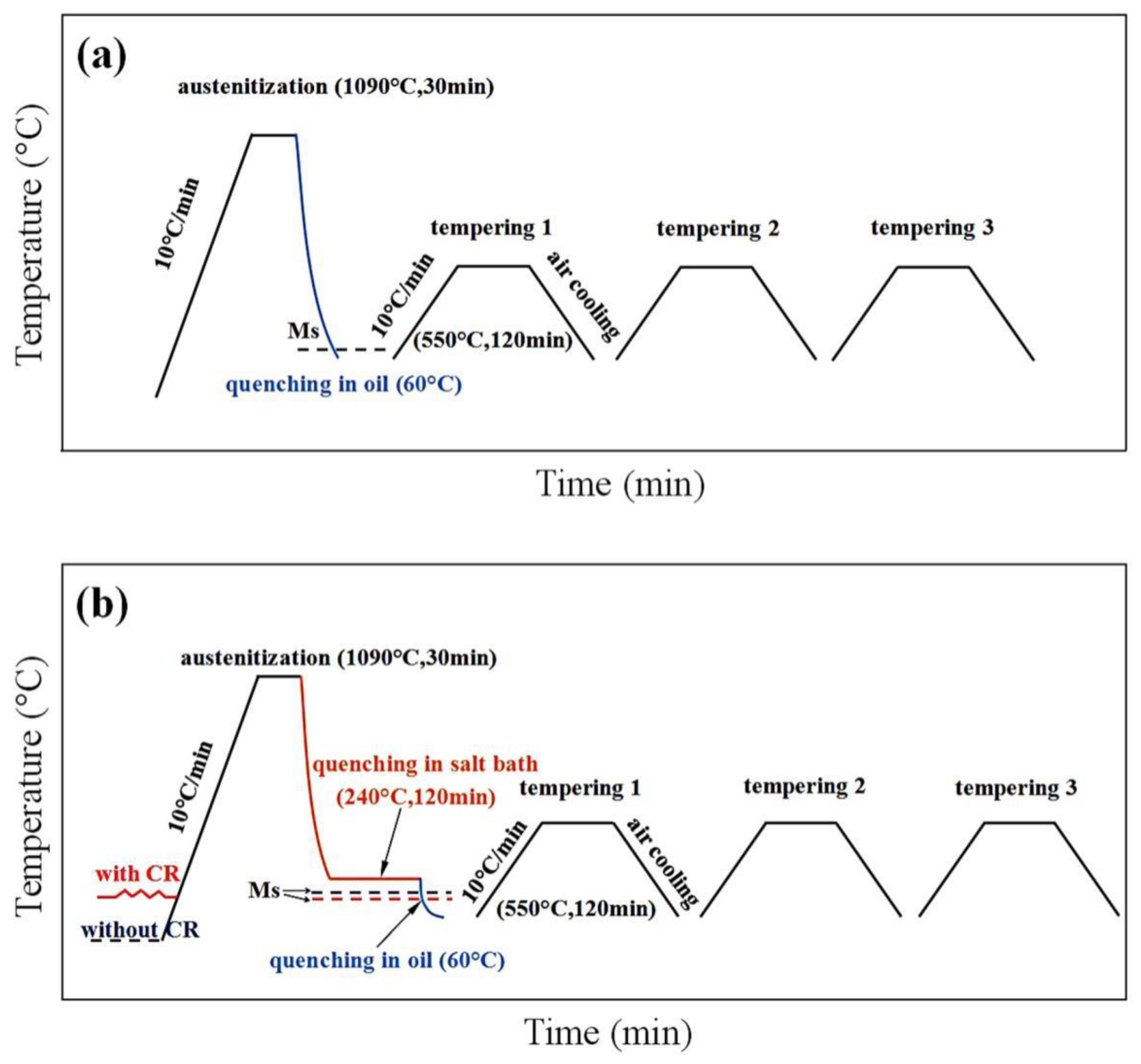
Figure 2.
(a) Dilation versus temperature curves at the cooling rate of 10 °C/s; (b) magnification of (a) to determine the Ms temperature.
Figure 2.
(a) Dilation versus temperature curves at the cooling rate of 10 °C/s; (b) magnification of (a) to determine the Ms temperature.
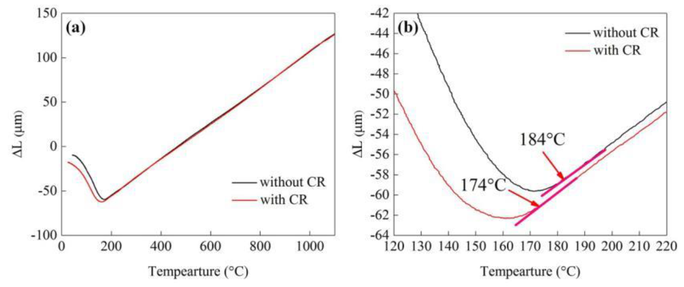
Figure 3.
Microstructure of the spheroidized experimental steel characterized by EBSD: the grain boundaries maps (a) without and (b) with CR; the distribution of misorientation angle (c) without and (d) with CR; the Kernel Averaged Misorientation (KAM) maps (e) without and (f) with CR. (EBSD: electron backscatter diffraction).
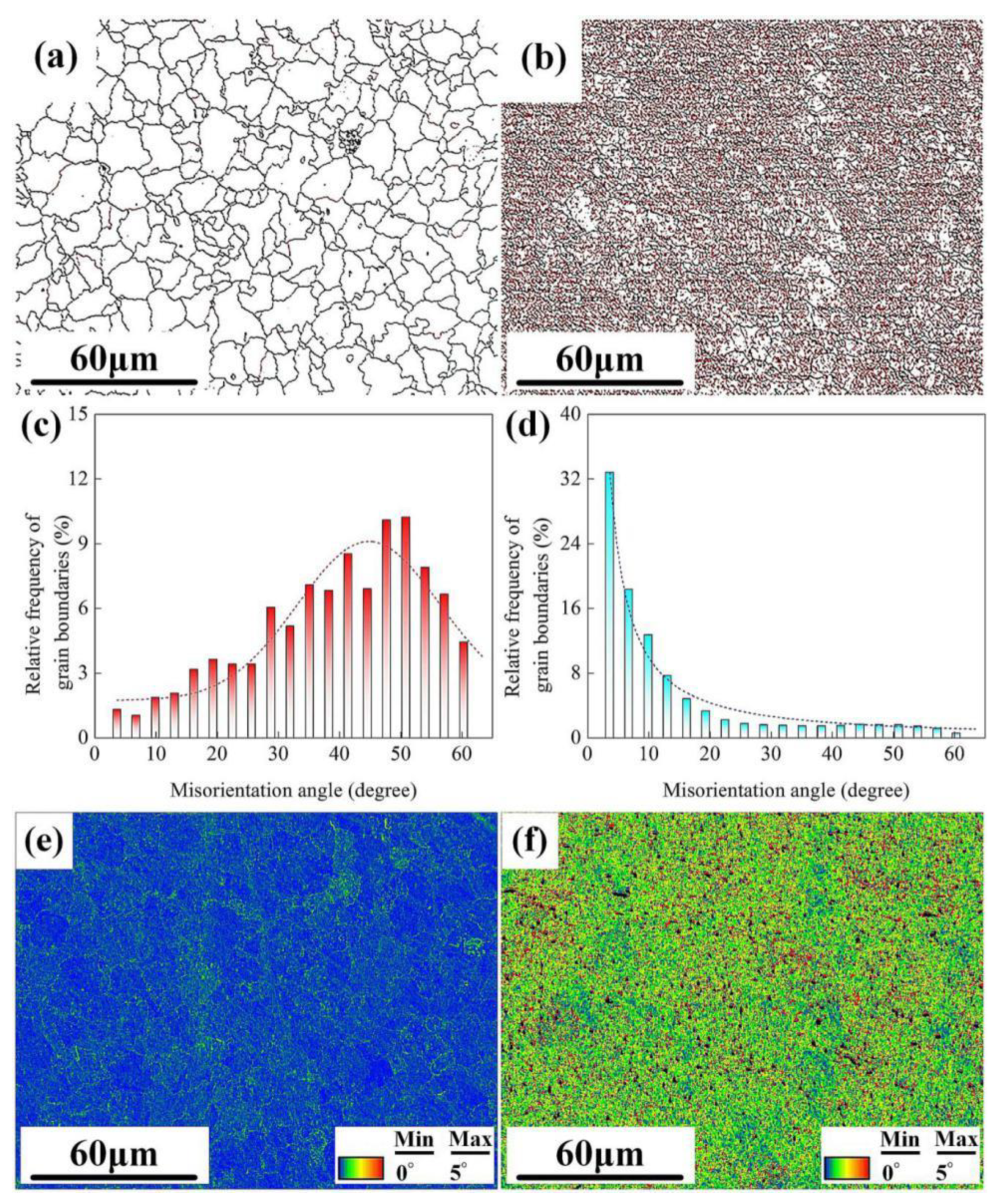
Figure 4.
SEM micrographs of as-quenched specimens: (a) Q-T process and austempering process (b) without and (c) with CR; (d) and (e) EDS spectrum of marked carbides (M/A: Martensite-Austenite islands; B: Lower bainite).
Figure 4.
SEM micrographs of as-quenched specimens: (a) Q-T process and austempering process (b) without and (c) with CR; (d) and (e) EDS spectrum of marked carbides (M/A: Martensite-Austenite islands; B: Lower bainite).
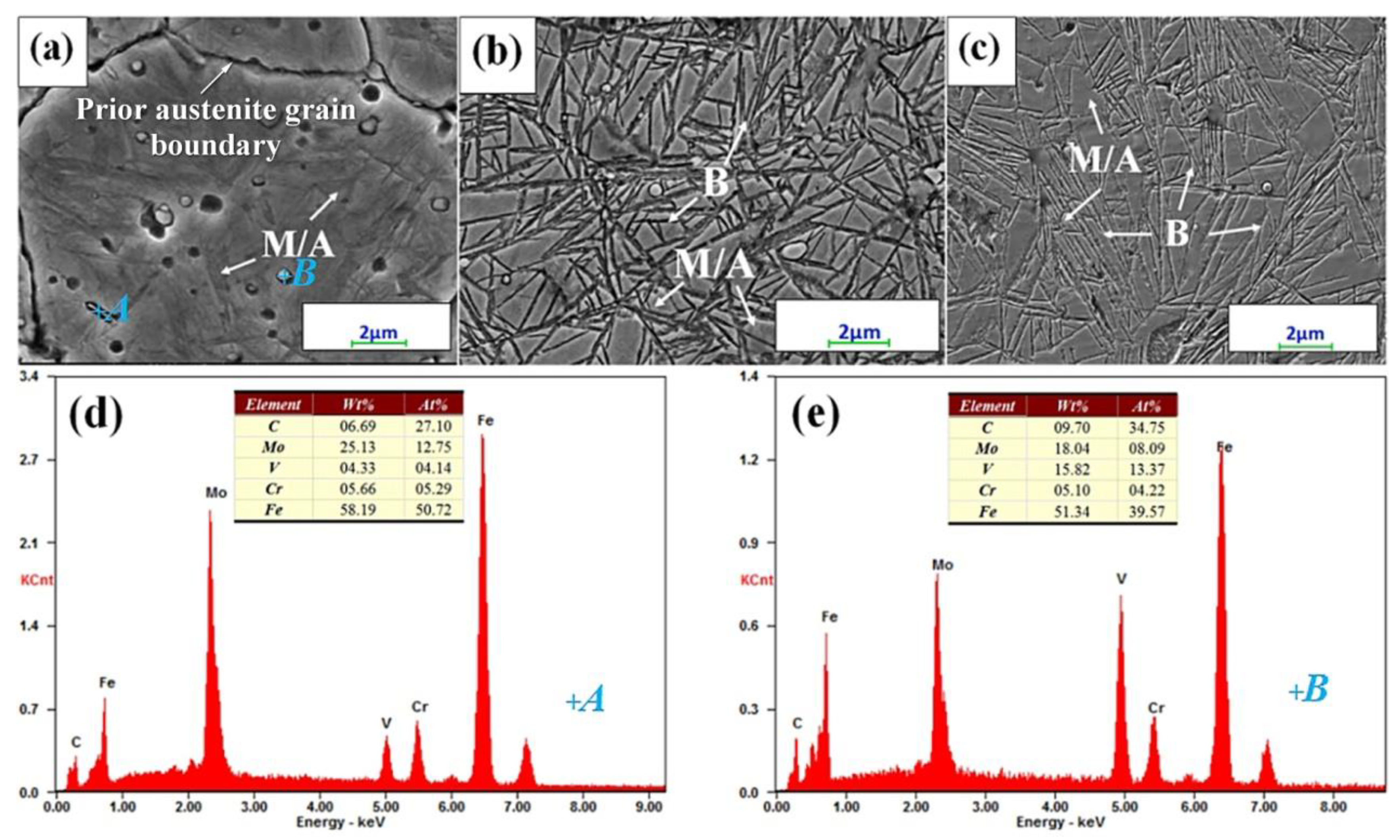
Figure 5.
X-ray diffraction patterns of as-quenched specimens: (a) Q-T process and austempering process (b) without and (c) with CR.
Figure 5.
X-ray diffraction patterns of as-quenched specimens: (a) Q-T process and austempering process (b) without and (c) with CR.
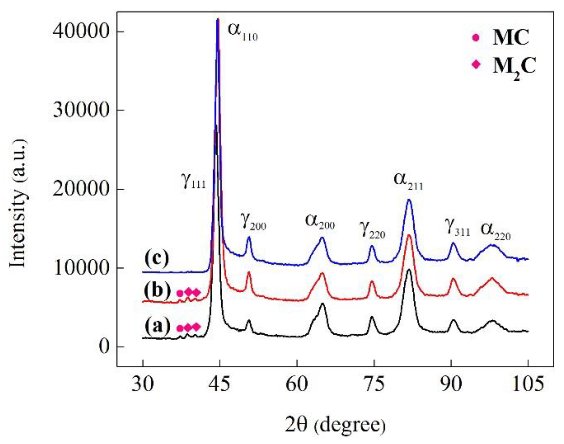
Figure 6.
SEM micrographs of tempered specimens: (a) Q-T process and austempering process (b) without and (c) with CR.
Figure 6.
SEM micrographs of tempered specimens: (a) Q-T process and austempering process (b) without and (c) with CR.
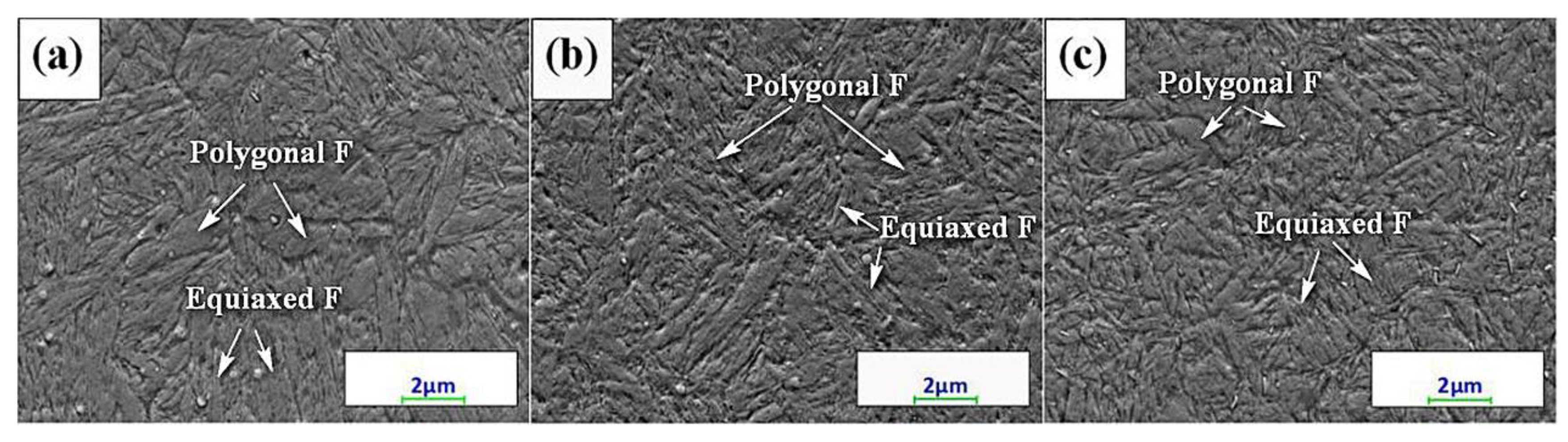
Figure 7.
X-ray diffraction patterns of tempered specimens: (a) Q-T process and austempering process (b) without and (c) with CR.
Figure 7.
X-ray diffraction patterns of tempered specimens: (a) Q-T process and austempering process (b) without and (c) with CR.
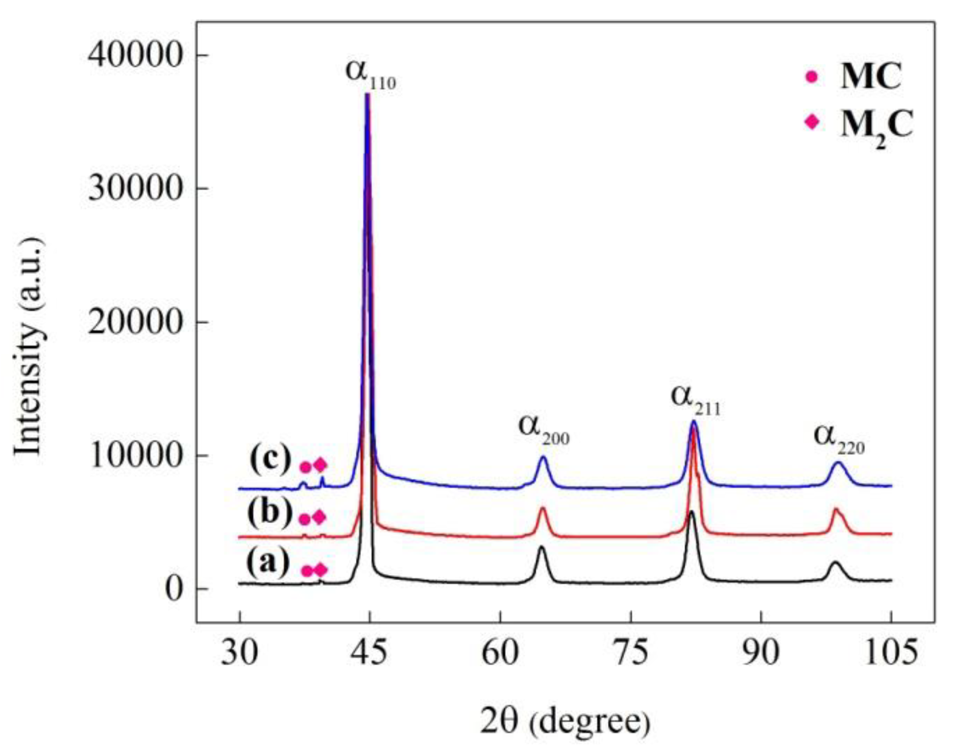
Figure 8.
TEM micrographs of the Q-T specimen after (a) quenching and (c) tempering, and the austempered specimen with CR after (b) quenching and (d) tempering. (F: Ferrite; UC: Undissolved carbide).
Figure 8.
TEM micrographs of the Q-T specimen after (a) quenching and (c) tempering, and the austempered specimen with CR after (b) quenching and (d) tempering. (F: Ferrite; UC: Undissolved carbide).
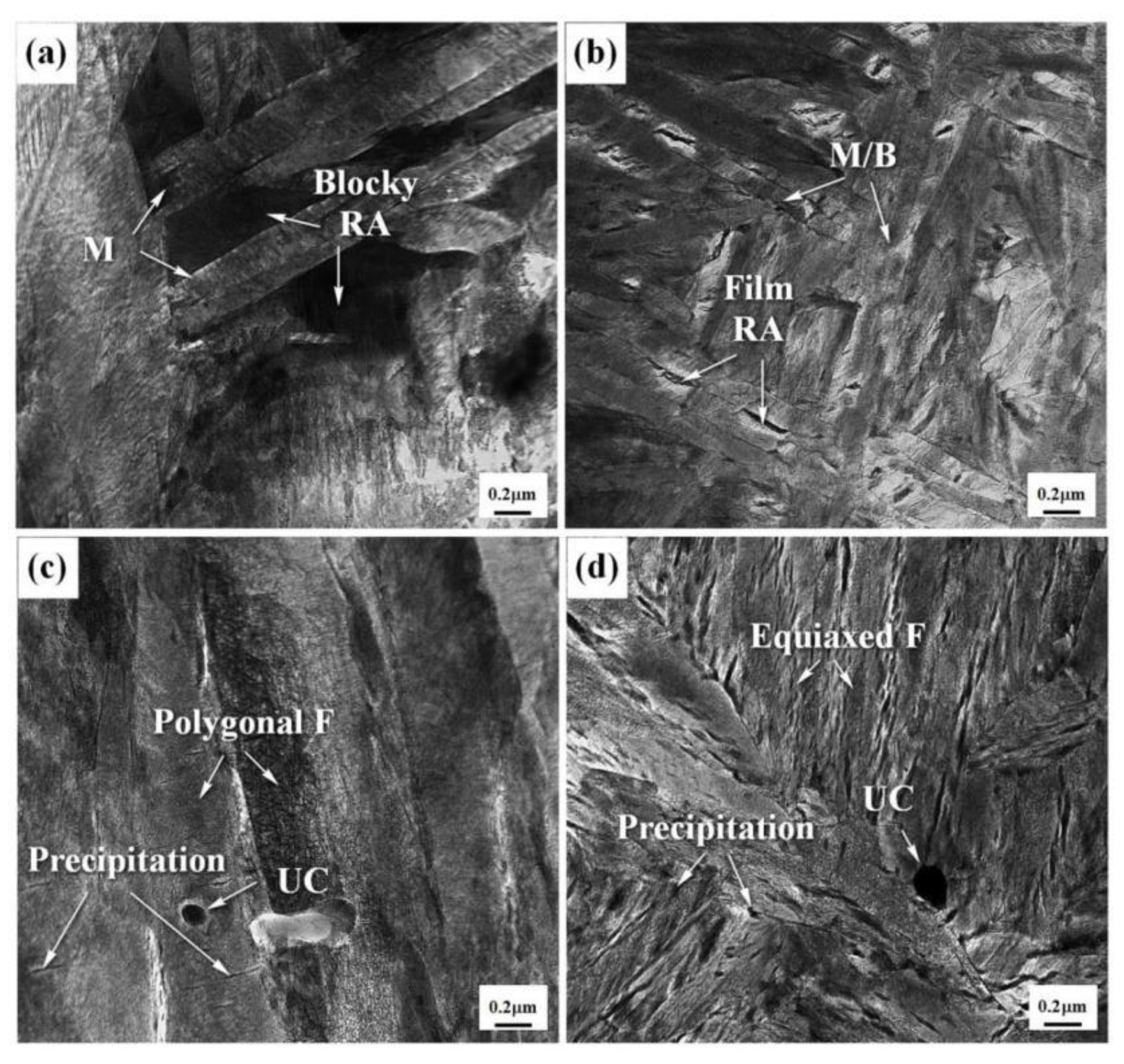
Figure 9.
Mechanical properties of specimens subjected to Q-T process and austempering process without and with CR after tempering: (a) impact toughness; (b) ultimate tensile strength; (c) hardness; (d) the stress-strain curves.
Figure 9.
Mechanical properties of specimens subjected to Q-T process and austempering process without and with CR after tempering: (a) impact toughness; (b) ultimate tensile strength; (c) hardness; (d) the stress-strain curves.
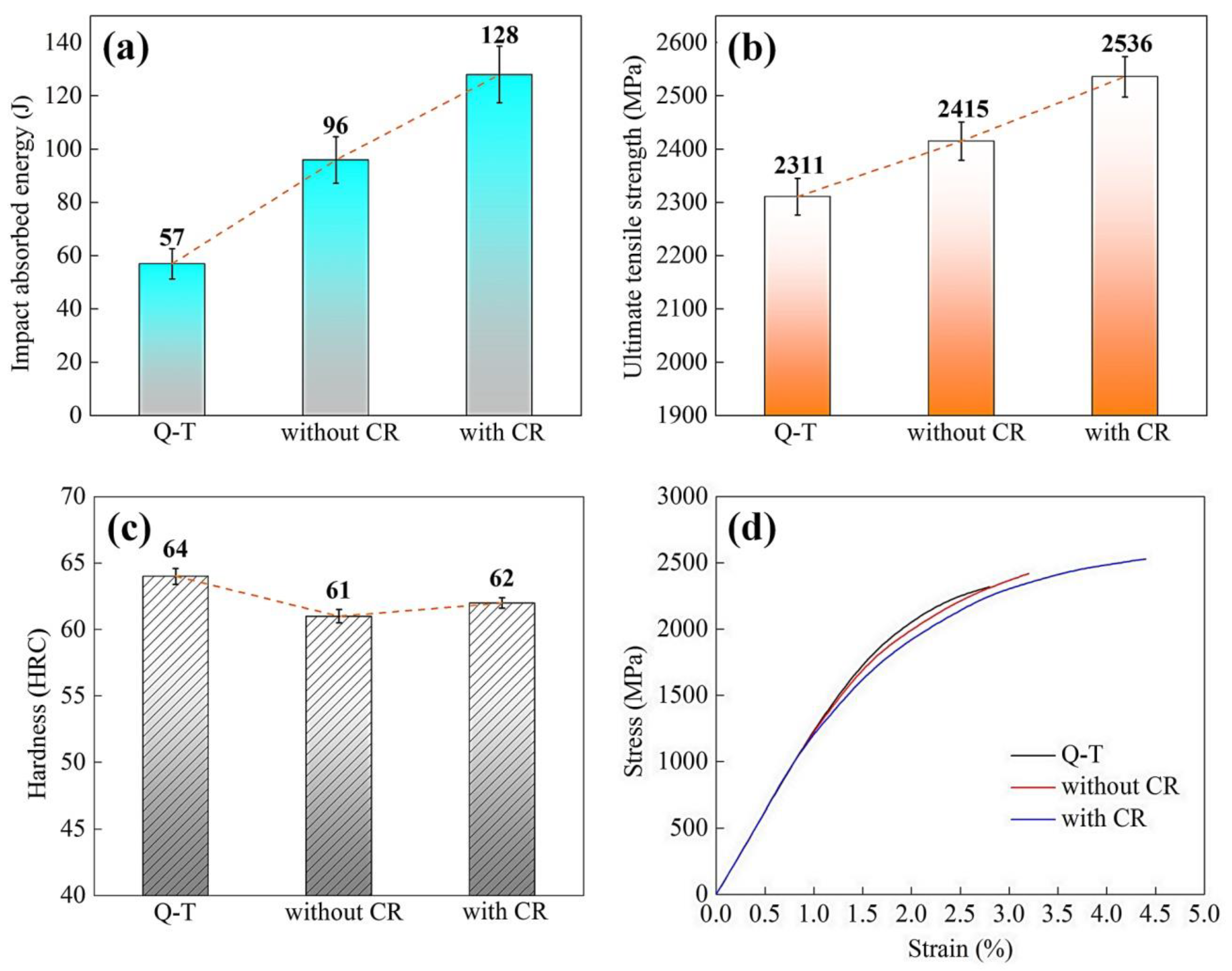
Figure 10.
The fractographies of the Q-T specimen and austempered specimen without and with CR: (a–c) the fibrous region; (d–f) the crack propagation region.
Figure 10.
The fractographies of the Q-T specimen and austempered specimen without and with CR: (a–c) the fibrous region; (d–f) the crack propagation region.

Table 1.
Chemical composition of tested M50 bearing steel (wt. %).
| C | Cr | Mo | V | Mn | Si | W | Fe |
|---|---|---|---|---|---|---|---|
| 0.80 | 4.06 | 4.20 | 1.08 | 0.22 | 0.25 | 0.16 | Bal. |
© 2020 by the authors. Licensee MDPI, Basel, Switzerland. This article is an open access article distributed under the terms and conditions of the Creative Commons Attribution (CC BY) license (http://creativecommons.org/licenses/by/4.0/).
Share and Cite
MDPI and ACS Style
Qian, D.; He, Y.; Wang, F.; Chen, Y.; Lu, X. Microstructure and Mechanical Properties of M50 Steel by Combining Cold Rolling with Austempering. Metals 2020, 10, 381. https://doi.org/10.3390/met10030381
AMA Style
Qian D, He Y, Wang F, Chen Y, Lu X. Microstructure and Mechanical Properties of M50 Steel by Combining Cold Rolling with Austempering. Metals. 2020; 10(3):381. https://doi.org/10.3390/met10030381
Chicago/Turabian StyleQian, Dongsheng, Yuangeng He, Feng Wang, Yun Chen, and Xiaohui Lu. 2020. "Microstructure and Mechanical Properties of M50 Steel by Combining Cold Rolling with Austempering" Metals 10, no. 3: 381. https://doi.org/10.3390/met10030381
Note that from the first issue of 2016, this journal uses article numbers instead of page numbers. See further details here.