Article

Functionally-Graded Metallic Syntactic Foams Produced via Particle Pre-Compaction

Centre for Mass and Thermal Transport in Engineering Materials, School of Engineering, The University of Newcastle, Callaghan, NSW 2308, Australia
*
Author to whom correspondence should be addressed.
Metals 2020, 10(3), 314; https://doi.org/10.3390/met10030314
Submission received: 6 February 2020 / Revised: 21 February 2020 / Accepted: 24 February 2020 / Published: 28 February 2020
(This article belongs to the Special Issue Advances in Metal Casting Technology)

Abstract

:
This paper introduces a novel functionally graded metallic syntactic foam. The investigated foams are manufactured while using infiltration casting where molten A356 aluminum flows into the interstitial voids of packed expanded perlite (EP) particle beds. The partial pre-compaction of particle beds enables the creation of distinct and reproducible density gradients within the syntactic foam. In this study, the samples are produced using four gradually increasing compaction forces and are compared to non-compacted samples. X-ray imaging is used to detect the resulting spatial variation of foam density. In addition, quasi-static compression tests are performed to determine the mechanical foam properties. The results suggest that particle pre-compaction is an efficient tool for tailoring the density and mechanical properties of these novel functionally graded materials.

1. Introduction

Metallic foams are multi-functional materials that combine low-density, high strength, damping, and controlled energy absorption with a large surface area and excellent thermal and electrical conductivity [1,2]. Unlike polymer foams [3], they are suitable for application at elevated temperatures and in chemically aggressive environments. As such, they are envisioned as structural and functional materials for a wide range of applications [3]. A major impediment to their widespread use has been their relatively high cost, which has given rise to a new generation of metallic foams [4]. One recent development is a focus on metallic syntactic foams (MSFs). In these materials, porosity is introduced by combining hollow [5,6,7,8] or inexpensive porous particles [9,10,11,12,13] with a metallic matrix. This approach enables the control of pore geometry and negates the need for costly foaming agents and manufacturing equipment [14].
Introducing a gradient is a known method for controlling material behavior [15]. In the case of metallic foams, density is usually the single most important property. Density vastly determines material strength and energy absorption capability. Therefore, the manufacturing of functionally graded (FG) foams with a spatial density variation has been previously studied in the literature. Most of this prior research was focused on closed-cell aluminum foams. He et al. [16] investigated the dynamic compression of FG closed-cell aluminum foam with a longitudinal pore size variation. Their results indicated the different mechanical behavior of uniform (i.e., foams without a significant change in density) and FG samples. Importantly, the FG structures showed an extended stress plateau, which is beneficial for the absorption of impact energy at controlled accelerations. In [17] FG closed-cell aluminum, foam was subjected to quasi-static compression testing. It was shown that the deformation initiates within low-density regions and then progressively extends to higher-density sections in a sequential deformation mode. Hangai et al. [18] manufactured two-layered closed-cell aluminum foams while using different amounts of foaming agents in each layer. The resulting spatial variation of porosity altered the deformation of the FG sample and two distinct plateau regions were observed. In another study [19] radially graded closed-cell aluminum foam was used to fabricate foam-filled tube structures. The concentration of smaller pores in the outer sections of the graded foam created a higher local strength, which increased its cohesion and interaction with the tube. In turn, this improved the crushing resistance of the material. Fan et al. [20] numerically investigated metal hollow sphere foams under dynamic loading. They observed optimum energy absorption when the testing load first affected the higher density side of the material.
The aim of this research study is to manufacture functionally-graded metallic syntactic foams (FG-MSF) with a tailored porosity arrangement along its longitudinal direction. It was previously shown [21,22] that using two different particle types could create a functional gradient. This enables the close control of the mechanical properties and energy absorption of the MSFs. In [21], FG-MSFs were manufactured while using two different types of particles, i.e., expanded perlite (EP) and activated carbon (AC) particles. Due to the different physical and mechanical properties of these particles, their respective MSF layers deformed in a distinctly different manner. In FG-MSFs, the catastrophic shear failure of the AC layer was successfully suppressed due to a smaller aspect ratio that prevented sample bisection. As a result, improved overall energy absorption of FG-MSF was found compared to uniform MSFs containing either particle type. Moreover, it was shown in [22] that increasing the number of layers (whilst decreasing their height) does not alter the deformation mechanism within individual layers. However, overall energy absorption was increased due to the earlier arrest of shear fractures in multi-layered FG-MSFs. One limitation of combining multiple particles to produce FG-MSF is the difficulty in obtaining gradual property changes. For these previously investigated layered structures, the properties (density, strength) rapidly change across the layer interphases.
Broxtermann et al. [23] manufactured MSFs by the pre-compaction of EP particles prior to infiltration casting. The aim of this procedure was the manufacturing of MSFs with a higher porosity. This was achieved by reducing the interstitial particle volume and, thus, the available melt volume prior to casting. Interestingly, this study revealed distinct density gradients in samples due to the friction effects between the particles themselves and their containing vessel. The study attempted to counteract these gradients by a modification of the pre-compaction procedure. However, these results also gave rise to a new strategy, i.e., the use of a single compressible particle type to produce functionally graded foams. The current study pursues this idea for the first time by using expanded perlite particles in a A356 alloy matrix. To achieve functional grading, the particle volume fraction of the foam is spatially altered in a reproducible manner. This is achieved by controlled particle pre-compaction prior to infiltration casting. Unlike in the previous study, only fractions of the particles are compressed to increase the density gradient within the material. The resulting density gradient is analysed and its impact on the mechanical foam properties is determined.

2. Materials and Methods

All of the samples were manufactured while using the infiltration casting procedure first described in [24]. In brief, a packed bed of porous particles is infiltrated with an A356 metallic melt to form metallic syntactic foam. For the current study, the expanded perlite particles were selected as the filler. These porous particles are lightweight (particle density 0.16–0.18 g/cm3), inexpensive (USD$ 0.13 per litre, December 2019), and, importantly, can be compressed to increase their packing density [23,24]. The particles that were used in this study were sieved between the mesh sizes of 2 mm (lower limit) and 2.8 mm (upper limit). Unlike hollow particles that are prone to fracture during compression and, thus, become infiltrated with melt, expanded perlite particles are composed of a large number of small pores. Consequently, particle compression only exposes a small number of surface pores, whereas most of the particle porosity is unaffected. This behaviour has been utilized in the current study, where two-layered FGMs were produced. In the first layer, particles were inserted into a crucible assisted by vibration to achieve dense packing. Next, a compressive force was gradually applied while using a 5 kN Shimadzu (Shimadzu manufacturing company, Kyoto, Japan) compression testing machine (1 mm/min.) until a target value of either 150, 250, or 350 N was reached. These compressive forces flattened the contact points of adjacent particles, resulting in denser packed particle beds. Naturally, this effect increased with the compaction force. For the second layer, additional particles were deposited on top of the compacted layer as indicated in the schematics (see Figure 1a). No vibration was performed to prevent the loosening of the first layer. For high compaction forces, the resulting change in particle packing density is clearly visible at the sample surfaces (e.g., see Figure 1b). Following casting, the upper and lower surfaces of all samples were machined to ensure similar heights of the compacted and non-compacted layers. The curved surfaces were not machined and each cast yielded one sample. For improved mechanical properties, all of the samples were further subjected to a T6 thermal treatment [23]. To this end, the samples where kept at 540 °C for 16 h followed by water quenching. The treatment was completed by artificial aging at 160 °C for 10 h.

2.1. Physical Properties

The (average) density of all the samples was calculated as the fraction of MSF mass ( m ) and volume ( V )
ρ MSF = m V
The sample height h and diameter d were determined while using a precision calliper at three different locations to determine the cylindrical sample volume. The average values were then inserted into V = π 4 · d 2 · h . Next, the volume fraction of the metallic matrix ( ϕ M ) can be estimated using
ϕ M = m m EP ρ Al V
The use of this equation requires the knowledge of the solid aluminum density (2.68 g/cm3) and the combined mass of expanded perlite particles ( m EP ) . For the non-compacted samples, this particle mass can be estimated based on the EP particle bulk density ( ρ EP , B = 0.09 g/cm3 [25]) and the sample volume, i.e., m EP = ρ EP , B · V . Unfortunately, this approach cannot be applied in the case of the pre-compacted samples, as compaction significantly increases the EP particle bulk density. Instead, the physical properties of the non-compacted layer in FG-MSF were assumed to exhibit the average volume fraction ( ϕ M ¯ ) and density ρ MSF ¯ of the non-compacted samples. To estimate the properties of the compacted layer, its mass ( m C ) is estimated according to
m C = m V 2 · ρ MSF ¯
The expression V 2 · ρ MSF ¯ estimates the mass of the non-compacted layer in FG-MSF as each layer encompasses half of the total sample volume ( V ) . Next, the matrix volume fraction in the compacted layer ( ϕ M , C ) can be calculated while using a modified Equation (2):
ϕ M , C = m C m EP , C ρ Al V 2
The combined mass of expanded perlite particles in the compressed layer ( m EP , C ) was measured during manufacturing. However, an additional inaccuracy is introduced due to the machining of the samples, which removes some of the compacted perlite particles resulting in a slight overestimation of m EP , C . Limiting the machining of the samples minimised this effect. An additional inaccuracy stems from the fact that the height of both layers slightly deviates in most samples due to the difficulty of precisely locating the interface on the outer sample surface. The overall metal volume fraction of FG-MSF is then estimated while using ( ϕ M , C + ϕ M ¯ ) / 2 .

2.2. X-ray Imaging

X-ray imaging was conducted in order to investigate the density gradient within the samples. All of the scans were performed on a Bruker Skyscan Microtomographic Scanner 1172 (Billerica, MA, USA) with 100 kV source voltage and 100 μA source current. The samples were scanned in four segments to achieve a sufficiently high resolution, i.e., a pixel size of 35.32 μm. These segments were then automatically merged to obtain sample projections with a final resolution of 1000 × 524 pixels. Five different projections were captured of each sample, with an incremental angle increase of 60 degrees and the obtained data were averaged. In all X-ray projections, dark grey values (minimum 0 = black) correspond to a high material density and light grey values (maximum 256 = white) indicate a low density (Figure 2). For an easier interpretation of the density gradient, the average grey level of each horizontal line of pixels is calculated in Figure 3 and plotted versus the sample height (i.e., the vertical direction).

2.3. Mechanical Testing
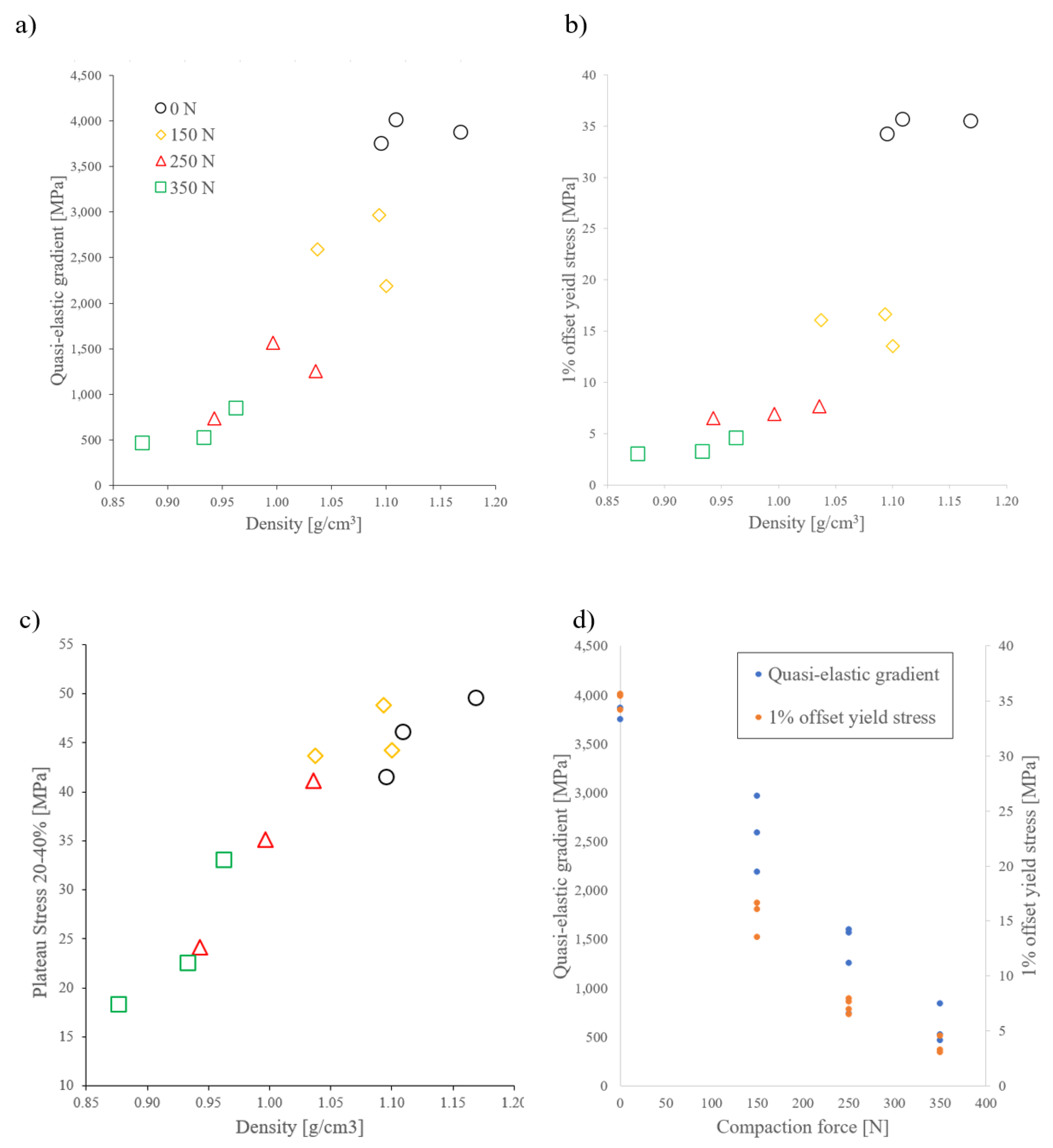
Compressive testing was performed on a 250 kN servo-hydraulic Material Testing System (MTS, Eden Prairie, MN, USA). All of the tests were quasi-static with a crosshead displacement speed of 1 mm/min. The load cell force and machine crosshead displacement were captured throughout the compression and converted into engineering stress ( σ ) and strain ( ε ) based on the initial sample dimensions (see Table A1). The samples were compressed between two steel platens that were lubricated with CRC® 5-56 (CRC Industries, NSW, Australia) multipurpose lubricant to minimize the frictional effects.
All subsequent data evaluation followed ISO13314 [26]:
  • The quasi-elastic gradient E corresponds to the maximum slope of the stress-strain data at low strains ( ε < 0.05 ). Following ISO13314, this value is selected on behalf of Young’s modulus. Young’s modulus is difficult to measure for metallic foams, as it is sensitive to settling effects and a direct attachment of strain gauges to the sample surface is usually not possible due to surface pores.
  • The 1% offset yield stress ( σ 1.0 ) is the stress at 1.0% plastic deformation.
  • The plateau stress ( σ Pl ) is the arithmetic mean of the stresses between ε = 0.2 0.4 .
  • The volumetric energy absorption ( W ) is obtained by the integration of the stress-strain curve according to Equation (5),
    W = 0 0.5 σ · d ϵ

3. Results and Discussion

3.1. X-ray Imaging

Prior to destructive testing, two samples per compaction force were subjected to X-ray imaging. Selected projections are shown in Figure 2, below. In all of the projections, lighter grey levels indicate that a larger amount of X-rays have penetrated through the sample and can thus be related to a lower local sample density. The brightness increases towards the left and right edges of the projections for the same reason and due to the cylindrical sample geometry. It can additionally be noted that the brightness towards the edges, as well as, towards the interface of the compacted volume increases with increasing compaction force. This can be attributed to the higher particle volume fraction that is caused by the particle compaction. In the case of the non-compacted sample (a), an approximately constant grey level is observed throughout the sample height. In all pre-compacted samples (b–d), a clearly defined interphase can be seen separating two distinct layers. It can further be observed that the brightness (and thus the porosity) of the compacted layer increases with higher compaction forces.
These projections were further processed to better analyse the density gradients. To this end, the average grey level of each horizontal line in these images was determined and plotted against the vertical direction (i.e., the sample height). These grey level values are dimensionless and defined between 0 (black) and 255 (white). The resulting grey level curves are shown in Figure 3, below. The black curve represents the non-compacted sample and no sudden changes in density are observed. However, a gradual density increase is detected that has been previously explained by friction effects between particles and the surfaces of their containment vessel during particle packing [23]. The density of the non-compacted layers in FG-MSF (height 20 mm) is higher when compared to the non-compacted MSF. The likely explanation is the lack of particle bed vibration in FG-MSF, which was avoided to prevent the loosening of the already compacted layer. Applying a compaction force of 150 N distinctly decreases the density of the compacted layer (yellow curves). This trend continues for higher compaction forces and steadily decreasing layer densities are observed.
The high-density FG-MSF interphase layers that were first observed in Figure 2 are clearly visible as sudden density changes in Figure 3 (see dashed box). The occurrence of these interphases can be explained based on the schematics presented in Figure 4. Particle pre-compaction flattens the compacted layer, resulting in a relatively large interstitial volume with the next non-compacted particle layer. This interphase is then infiltrated with melt aluminium during casting resulting in a low local porosity. The schematics further explains the distinct grey level/porosity oscillations apparent in Figure 3. Mono-sized spherical particles tend to arrange themselves in regular patterns [27]. Consequently, the grey level oscillation length ( Δ h ) coincides with the average particle diameter. As further visible in Figure 3, these oscillations tend to attenuate with increasing compaction force as the particle shape is altered.

3.2. Physical Properties

The physical sample properties are plotted versus the compaction force in Figure 5. As expected, the sample density (blue markers) steadily decreases with the compaction force. The sample density further closely correlates with the matrix volume fraction ( ϕ M ) (orange markers). This is due to a significantly higher density of the aluminium when compared to the particles, which thus determines the sample density. With increasing compaction force, less interstitial volume remains inside the compacted layer (see Figure 4) and it can be infiltrated by melt aluminium. Consequently, the matrix volume fraction steadily declines.

3.3. Mechanical Properties

Figure 6 shows the compressive stress-strain data. Individual data sets are plotted as thin lines and the thick lines represent the average stress-strain response for a given compaction force. Similar to e.g. [21], for the functionally-graded samples, two distinct stress plateaus can be observed.
At low strains, the non-compacted sample (black line) exhibits the highest stress. The initial stresses ( ε 0.3 ) gradually decrease with increasing compaction force. The explanation is the concentration of initial foam deformation in the weakest foam subvolume, in this case the compacted layers. The strength of the compacted layer is largely determined by the matrix volume fraction ( ϕ M ) and, thus, the compaction force (see Figure 5). At higher strains ( ε 0.4 ), the stresses of the FG-MSF exceed the non-compacted foam. At this point, the compacted layer had entered the densification regime and the deformation shifts to the non-compacted FG-MSF layer. The non-compacted layer of FG-MSF has a higher density (and thus strength) when compared to the non-compacted sample due to a lack of particle vibration, as discussed earlier.
Figure 7 shows the corresponding deformation mechanism of the samples. Light-photography was taken during compression at the macroscopic strains ε = 0 ,   0.1 ,   0.2 ,   0.4 and 0.6 . The non-compacted samples exhibit distinct barrelling that originates from the centre of the sample (see white arrows). At higher strains, the ongoing barrelling eventually causes vertical splitting of the sample. In the case of FG-MSF, the initial deformation is largely limited to the weaker, i.e., the compacted, layer. For the compaction force of 150 N, some barrelling is observed; however, this deformation mechanism diminishes for the higher compaction forces. Instead, layer-by-layer collapse without significant lateral deformation is found. Interestingly, no evidence of macroscopic shear band formation was found in any of the tested samples. The shear failure of MSF is characteristic for brittle matrices [28]. Thus, an advantage of two volumes with different particle volume fractions is the increased control over the deformation behaviour. Shear bands can be supressed to prevent catastrophic failure of the sample (smaller aspect ratio). This is of particular interest for materials showing brittle deformation and shear failure. It has been previously shown that T6 thermal treatment increases the ductility of the matrix alloy and the MSFs [29], which favours layer-by-layer deformation. At higher strains ε > 0.3 , the deformation transitions to the non-compacted FG-MSF layers. This transition coincides with a distinct stress increase (see Figure 6). The non-compacted layer of FG-MSFs then deforms via barrelling that is similar to the non-compacted samples.
The stress-strain data that are shown in Figure 6 were processed following ISO13314. Figure 8 shows the obtained effective material properties and Appendix A, Table A2 list the numerical values.
Globally, the quasi-elastic gradient (see Figure 8a) exhibits a linear trend with respect to the average sample density. The highest stiffness is observed for the non-compacted samples, which also exhibit the highest density and, thus, the highest metal volume fraction. A clear correlation between the quasi-elastic modulus and the sample density is observed. However, this is superimposed by a strong scattering between individual samples. In the case of FG-MSF, the stiff (non-compacted) and softer (compacted) layers are arranged in series. In this case, the elastic stiffness can be estimated while using the harmonic mean of the individual layer stiffnesses and is thus dominated by the properties of the softer (compacted) layer. Hence, a clear correlation between the compaction force and quasi-elastic modulus can be expected. Figure 8d visualises this relationship, where the quasi-elastic modulus (blue markers) is plotted against the compaction force. In [23], samples only containing pre-compacted particles (150 N) were investigated. Their quasi-elastic gradient is between 830–1140 MPa and, thus, below the corresponding values of the functionally graded structures (2191–2964 MPa). However, as the entire particle beds were compacted, the sample densities are also significantly lower, i.e., 0.72–0.76 g/cm3. Their lower stiffness is likely related to density gradients within these samples resulting in high porosity subvolumes.
The 1% offset yield stress (see Figure 8b) shows a distinct dependence on the compaction force. A stepwise increase is observed for a decreasing compaction force. It is shown in Figure 7 that the initial deformation is limited to the weaker (compacted) layer. Hence, the strength of this layer will determine the 1% offset yield stress explaining the observed pattern. The correlation between initial strength and compaction force is further demonstrated in Figure 8d, where a near linear relationship is found. The comparison of samples that were manufactured with the same compaction force reveals only a marginal increase of the offset yield stress with increasing density. A previous study on completely compacted samples [23] yielded 1% offset yield stresses of 4.5–7.1 MPa for a compaction force of 150 N. These values are significantly below the findings of the current study (13.54–16.65 MPa) and are again attributed to distinct density gradients within the completely compacted samples.
In Figure 8c, the plateau stress is plotted versus the average foam density. This material property appears to be controlled by the sample density. Independent of the compaction force, the plateau stress continuously increases with the average sample density. Higher strains can explain the distinct deviation from the pattern of the 1% offset yield stress data (see. Figure 8b). The plateau stress is the arithmetic stress mean between 20 and 40% macroscopic compression. At this stage, deformation transitions towards the non-compacted layer (see Figure 7). Consiequently, the metal volume fraction of both layers (and thus the sample density) determines the magnitude of the plateau stress.
The energy absorption (not plotted, the values are listed in the Appendix, Table A2) is determined to be similar to the plateau stress and thus exhibits the same trend.

4. Conclusions

In this paper, functionally graded metallic syntactic foams were successfully produced while using a single compressible particle type, i.e., expanded perlite. Controlled particle pre-compaction prior to casting allowed for the manufacturing of samples with consistent and repeatable physical and mechanical properties. The key findings of this study are:
  • Particle pre-compaction locally decreases the density of the affected foam layer.
  • The magnitude of the pre-compaction force directly controls the elastic stiffness and initial strength of the foam samples.
  • In contrast, the plateau stress and energy absorption primarily depend on the overall sample density.
  • The stress-strain data of the functionally graded samples exhibits two distinct stress plateaus corresponding to the individual layers.
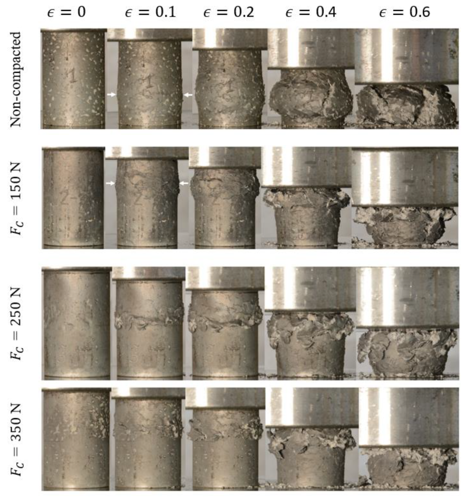
  • Non-compacted layers deform via barrelling, whereas compacted layers transition towards layer-by-layer deformation.

Author Contributions

T.F. initiated the Project, supervised its progress and wrote this publication. N.M., co-supervised this Project, participated in the sample manufacturing and wrote the introduction of this paper. L.Y. manufactured the samples, conducted mechanical testing and documented the results. S.B. contributed to Project planning, conducted the X-ray analysis, and provided advise for the sample manufacturing. All authors have read and agreed to the published version of the manuscript.

Funding

This research received no external funding.

Acknowledgments

We want to acknowledge the outstanding support by the University of Newcastle workshop staff of the Discipline of Mechanical Engineering.

Conflicts of Interest

The authors declare no conflict of interest.

Appendix A

Table A1. Geometric dimensions of samples.
Compaction Force
[N]
Height
[mm]
Diameter
[mm]
Volume
[cm3]
Mass
[g]
Density
[g/cm3]
Matrix Volume Fraction
[%]
41.9428.2226.2328.7301.1035.91
041.9228.2826.3330.7701.1738.59
41.9628.2926.3729.2591.1136.52
39.9728.3327.2526.1341.0433.60
15043.7028.3527.5130.1521.0936.11
43.9128.3227.5530.4201.1036.16
43.1428.3626.0127.1581.0032.24
25043.6128.3425.4025.9310.9430.08
43.5928.3725.3828.5341.0433.63
41.2328.3425.2024.3780.9429.34
35040.2728.3427.5924.4600.9630.33
40.2328.3427.6622.2490.8827.12
Table A2. Effective mechanical properties.
Compaction ForceDensityQuasi-Elastic Modulus1% Offset Yield StressPlateau StressVolumetric Energy Absorption
[N][g/cm3][MPa][MPa][MPa][MPa]
1.10374934.1941.5619.83
01.17387035.4849.6323.32
1.11400635.6746.0821.14
1.04259316.0743.7319.01
1501.09296416.6548.8621.38
1.10219113.5444.2119.11
1.0016027.9244.2919.08
2500.9415666.9335.1715.37
1.047356.5024.1311.27
0.9412557.6841.1316.99
3500.965213.2522.5011.08
0.888454.5433.0914.19

References

  1. Degischer, H.P.; Kriszt, B. Handbook of Cellular Metals Production, Processing, Application, 1st ed.; WILEY-VCH Verlag GmbH: Weinheim, Germany, 2002. [Google Scholar]
  2. Ashby, M.F.; Evans, A.; Fleck, N.A.; Gibson, L.J.; Hutchinson, J.W.; Wadley, H.N.G.; Delale, F. Metal Foams: A Design Guide; Butterworth-Heinemann: Oxford, UK, 2000. [Google Scholar]
  3. Garcia-Moreno, F. Commercial Applications of Metal Foams: Their Properties and Production. Materials 2016, 9, 85. [Google Scholar] [CrossRef]
  4. Lehmhus, D.; Vesenjak, M.; Schampheleire, S.; Fiedler, T. From Stochastic Foam to Designed Structure: Balancing Cost and Performance of Cellular Metals. Materials 2017, 10, 922. [Google Scholar] [CrossRef] [Green Version]
  5. Szlancsik, A.; Katona, B.; Bobor, K.; Májlinger, K.; Orbulov, I.N. Compressive behaviour of aluminium matrix syntactic foams reinforced by iron hollow spheres. Mater. Des. 2015, 83, 230–237. [Google Scholar] [CrossRef] [Green Version]
  6. Anantharaman, H.; Shunmugasamy, V.C.; Strbik, O.M.; Gupta, N.; Cho, K. Dynamic properties of silicon carbide hollow particle filled magnesium alloy (AZ91D) matrix syntactic foams. Int. J. Impact Eng. 2015, 82, 14–24. [Google Scholar] [CrossRef]
  7. Newsome, D.B.; Schultz, B.F.; Ferguson, J.B.; Rohatgi, P.K. Synthesis and Quasi-Static Compressive Properties of Mg-AZ91D-Al(2)O(3) Syntactic Foams. Materials 2015, 8, 6085–6095. [Google Scholar] [CrossRef] [Green Version]
  8. Katona, B.; Szebényi, G.; Orbulov, I.N. Fatigue properties of ceramic hollow sphere filled aluminium matrix syntactic foams. Mater. Sci. Eng. A 2017, 679, 350–357. [Google Scholar] [CrossRef] [Green Version]
  9. Taherishargh, M.; Belova, I.V.; Murch, G.E.; Fiedler, T. The effect of particle shape on mechanical properties of perlite/metal syntactic foam. J. Alloy. Compd. 2017, 693, 55–60. [Google Scholar] [CrossRef]
  10. Al-Sahlani, K.; Taherishargh, M.; Kisi, E.; Fiedler, T. Controlled Shrinkage of Expanded Glass Particles in Metal Syntactic Foams. Materials 2017, 10, 1073. [Google Scholar] [CrossRef] [Green Version]
  11. Broxtermann, S.; Vesenjak, M.; Krstulović-Opara, L.; Fiedler, T. Quasi static and dynamic compression of zinc syntactic foams. J. Alloy. Compd. 2018, 768, 962–969. [Google Scholar] [CrossRef]
  12. Linul, E.; Lell, D.; Movahedi, N.; Codrean, C.; Fiedler, T. Compressive properties of zinc syntactic foams at elevated temperatures. Compos. B. Eng. 2019, 167, 122–134. [Google Scholar] [CrossRef]
  13. Movahedi, N.; Taherishargh, M.; Belova, I.V.; Murch, G.E.; Fiedler, T. Mechanical and Microstructural Characterization of an AZ91-Activated Carbon Syntactic Foam. Materials 2018, 12, 3. [Google Scholar] [CrossRef] [Green Version]
  14. Gupta, N.; Rohatgi, P.K. Metal Matrix Syntactic Foams, Processing, Microstructure, Properties and Applications; DEStech Publication: Lancaster, PA, USA, 2015. [Google Scholar]
  15. Naebe, M.; Shirvanimoghaddam, K. Functionally graded materials: A review of fabrication and properties. Appl. Mater. Today 2016, 5, 223–245. [Google Scholar] [CrossRef]
  16. He, S.-Y.; Zhang, Y.; Dai, G.; Jiang, J.-Q. Preparation of density-graded aluminum foam. Mater. Sci. Eng. A 2014, 618, 496–499. [Google Scholar] [CrossRef]
  17. He, S.-y.; Lv, Y.-n.; Chen, S.-t.; Dai, G.; Liu, J.-g.; Huo, M.-k. Gradient regulation and compressive properties of density-graded aluminum foam. Mater. Sci. Eng. A 2020, 772, 138658. [Google Scholar] [CrossRef]
  18. Hangai, Y.; Takahashi, K.; Utsunomiya, T.; Kitahara, S.; Kuwazuru, O.; Yoshikawa, N. Fabrication of functionally graded aluminum foam using aluminum alloy die castings by friction stir processing. Mater. Sci. Eng. A 2012, 534, 716–719. [Google Scholar] [CrossRef]
  19. Zhang, Y.; Zang, X.-y.; Wang, K.; He, S.-y.; Liu, J.-g.; Zhao, W.; Gong, X.-l.; Yu, J. Fabrication of functionally radial graded metallic foam. Mater. Lett. 2020, 264, 127292. [Google Scholar]
  20. Fan, J.; Zhang, J.; Wang, Z.; Li, Z.; Zhao, L. Dynamic crushing behavior of random and functionally graded metal hollow sphere foams. Mater. Sci. Eng. A 2013, 561, 352–361. [Google Scholar] [CrossRef]
  21. Movahedi, N.; Murch, G.E.; Belova, I.V.; Fiedler, T. Functionally graded metal syntactic foam: Fabrication and mechanical properties. Mater. Des. 2019, 168, 107652. [Google Scholar] [CrossRef]
  22. Movahedi, N.; Conway, S.; Belova, I.V.; Murch, G.E.; Fiedler, T. Influence of particle arrangement on the compression of functionally graded metal syntactic foams. Mater. Sci. Eng. A 2019, 764, 138242. [Google Scholar] [CrossRef]
  23. Broxtermann, S.; Taherishargh, M.; Belova, I.V.; Murch, G.E.; Fiedler, T. On the compressive behaviour of high porosity expanded Perlite-Metal Syntactic Foam (P-MSF). J. Alloy. Compd. 2017, 691, 690–697. [Google Scholar] [CrossRef]
  24. Taherishargh, M.; Belova, I.V.; Murch, G.E.; Fiedler, T. Low-density expanded perlite–aluminium syntactic foam. Mater. Sci. Eng. A 2014, 604, 127–134. [Google Scholar] [CrossRef]
  25. Arifuzzaman, M.; Kim, H.S. Novel mechanical behaviour of perlite/sodium silicate composites. Constr. Build. Mater. 2015, 93, 230–240. [Google Scholar] [CrossRef]
  26. ISO13314:2011. Mechanical Testing of Metals—Ductility Testing—Compression Test for Porous and Cellular Metals; ISO: Geneva, Switzerland, 2011. [Google Scholar]
  27. Reimann, J.; Vicente, J.; Brun, E.; Ferrero, C.; Gan, Y.; Rack, A. X-ray tomography investigations of mono-sized sphere packing structures in cylindrical containers. Powder Technol. 2017, 318, 471–483. [Google Scholar] [CrossRef]
  28. Al-Sahlani, K.; Kisi, E.; Fiedler, T. Impact of particle strength and matrix ductility on the deformation mechanism of metallic syntactic foam. J. Alloy. Compd. 2019, 786, 292–299. [Google Scholar] [CrossRef]
  29. Movahedi, N.; Murch, G.E.; Belova, I.V.; Fiedler, T. Effect of Heat Treatment on the Compressive Behavior of Zinc Alloy ZA27 Syntactic Foam. Materials 2019, 12, 792. [Google Scholar] [CrossRef] [Green Version]
Figure 1. Functionally graded metallic syntactic foam (MSF): (a) schematics, and (b) completed sample.
Metals 10 00314 g001
Figure 2. X-ray imaging of selected samples: (a) non-compacted, (b) 150N, (c) 250 N, and (d) 350 N.
Metals 10 00314 g002
Figure 3. Average grey level intensity plotted versus sample height.
Metals 10 00314 g003
Figure 4. Schematics of particle and porosity distribution.
Metals 10 00314 g004
Figure 5. Physical properties of manufactured samples.
Metals 10 00314 g005
Figure 6. Compressive stress-strain curves of manufactured samples.
Metals 10 00314 g006
Figure 7. Deformation mechanism of samples under compression.
Metals 10 00314 g007
Figure 8. Effective mechanical properties of the compressed syntactic foam samples.
Metals 10 00314 g008

