Article

PbO-SiO2 Based Glass Coating of PbI2 Doped PbTe

Department of Materials Engineering, Ben-Gurion University of the Negev, Beer-Sheva 84105, Israel
*
Author to whom correspondence should be addressed.
Metals 2020, 10(2), 284; https://doi.org/10.3390/met10020284
Submission received: 21 January 2020 / Revised: 18 February 2020 / Accepted: 19 February 2020 / Published: 21 February 2020
(This article belongs to the Special Issue Thermoelectric Compounds: Processing, Properties and Applications)

Abstract

:
Thermoelectrics is one promising way of increasing the efficiency of machines and devices by reusing some of the waste heat produced. One obstacle for commercialization is the need to coat the materials to prevent sublimation and oxidation of the thermoelectric materials. Such coatings were designed for PbI2 doped PbTe using a (SiO2)0.68(PbO)0.3(B2O3)0.01(Na2O)0.01 based glass designed for operation at 500 °C. In this research various conditions of the coating process were examined. The effect of the atmosphere on the bonding and densification of the coating was studied using argon, vacuum and air. From the three air shows, the best bonding characteristics were from a better flow of glass and increased bonding between the oxidized PbTe layer and glass. This also created a PbO rich glass in the interface between the glass and the PbTe sample. The effect of 0, 3, and 6 wt. % NaCl additive to the solution was tested and showed that NaCl achieves better coverage due to high green body density, reaction of NaCl with the glass and removal of remaining CO2 from the glass in the form of decomposing Na2CO3. In addition, when testing the time and temperature, it was shown that the temperature of 520 °C was the minimum needed for high densification of the glass, but a duration shorter than 30 min did not allow for bonding of the glass to the substrate despite adequate densification. Finely, to obtain a well bonded coating with full coverage over the sample, the glass was coated with 6% NaCl in air at 520 °C for 30 min.

1. Introduction

In the pursuit of providing efficient and practical energy conversion methods, heat to energy recovery, using thermoelectric materials is one of the most promising technologies. Thermoelectric devices provide passive energy regeneration, while turning heat into electricity without any moving parts or control of operations. However, some challenges remain due to the need to operate at high temperatures, and the high sensitivity of most thermoelectric materials to oxidation and sublimation.
In Figure 1, some of these challenges are highlighted, such as finding materials and processes for metallization, hot-side brazing, and cold-side soldering at low temperature, where little to no reaction occurs with the thermoelectric element. One such major hurdle is overcoming degradation due to a high temperature exposure to the atmosphere, as marked in the figure. Thermoelectric devices can go through degradation under atmospheric environment due to two main mechanisms, oxidation and sublimation. Some studies have shown that sublimation is one of the most problematic degradation mechanisms for many thermoelectric materials such as PbTe [1], GeTe [1], Bi2Te3 [2], CoSb3 [3], Mg2Si [4], and more. PbTe-based materials are well-known state of the art materials for operation near 500 °C [5]. Several papers have suggested that the main degradation mechanism for PbTe materials is high temperature sublimation [1,6] near 500 °C in general and sublimation from grain boundaries in particular [7]. In addition, most high temperature thermoelectric generators need to be encased in inert gas [8] due to oxidation of the thermos-elements. Airtight coating allow work to be carried out in the air atmosphere and use without heavy and expensive atmosphere tight encasing.
Coating of thermoelectric materials have been suggested several times before using organic coating [9,10], ceramic coating [11], and aerogel casings [12]. However, such coatings tend to degrade at high temperature, crack, and are very expensive. Glass coating of PbTe is especially interesting, given most properties of glass can be controlled via its very wide range of compositions. In a recent study a glass based on PbO-SiO2 doped with both B2O3 and Na2O was suggested as a coating composition for PbTe based materials [13]. The glass is relevant for the coating since it has a low enough glass transition temperature (Tg = 470 °C) and softening point (Ts = 540 °C) to allow for high temperature operation (above 500 °C), but low temperature application (under 550 °C). In addition the coefficient of thermal expansion (CTE) should be similar to that of PbTe (CTE = 20 × 10−6 1/K) with this glass having a CTE of 8.2 × 10⁻⁶ 1/K from 100–400 °C and 33 × 10−6 1/K above Tg. Lastly it is assumed that picking a lead-based glass for a lead-based sample would promote the bonding between the coating and the sample. However, good properties of the glass are only one facet, since developing a coating procedure for the thermoelectric materials is still required in order to realize this endeavor. Such a procedure should not only concentrate on applying a thin coating layer on top of the thermoelectric material, but also ensure uniform coverage and minimal damaging of the thermoelectric materials.
The general coating challenges of semi-conductors, and thermoelectric materials include, among others, minimal–to-no diffusion between the base material and the coating; the coating procedure should be at a higher temperature than the device operation temperature, but lower than at which a major degradation occurs; and high wetting and flowability of the coating to prevent non-uniform coverage. Such conditions are hard to meet especially for thermoelectric materials, which require very specific conditions for fabrication. However, due to the high number of control variables this can be subtly improved by many factors. Some of them will be discussed in the next sections.
Many factors can affect the quality of glass coatings, some of which are easy to control, including the type of coating process (e.g., tape casting [14], air brushing [15], dip coating [16], CVD [17], and many more); the coating’s slurry characteristics (e.g., liquid or gas carrier’s state, particle size, and any binder or surfactant added to slurry); the surface roughness of the base material (i.e., very low surface roughness reduces the adhesion whereas very high surface roughness makes full coverage a problem with the need to fit into every crevice [18]); the coating’s atmosphere (which can be oxidizing inert or reducing, e.g. air, argon or hydrogen, respectively, or even vacuum) [19,20]; and lastly the temperature and time of the coating process should be controlled to obtain the best possible coating with minimal adverse effects on the thermoelectric properties. Since it is very difficult to run a systematic study taking into account all of these variables, in the current research some variables were kept constant, while others were first, separately optimized, and later on, taken as a constant for optimizing the next variable.
The coating technique is the most important variable as it affects all the other involved variables. Techniques, such as paint brushing [21], tape casting [14], spin coating [22], and air brushing [15] share many traits, but the main difference between them is the viscosity of the applied film, which can be further controlled for each technique individually. The current research is concentrated on paint brush coating, which is low cost and requires no special equipment. Considering the choice of brushing as the application technique, a liquid form is required as the suspender for the coating procedure, with potential additives like surfactants, binders, fining agents and others, being added into the mixture to create the coating suspension. To simplify the coating process as much as possible, a water-based slurry was used for the suspension, since silica is hydrophilic [23]. An additional control was concentrated on the ionic strength. The ionic strength can break up the electrostatic forces between glass particles therefore leading to much higher green density of the coating before the application of temperature [14]. These electrostatic forces can create a double layer between glass particles and prevent them from settling near each other. To increase the ionic strength, ionic modifiers, acting as fining agents, were examined. Some of the most common fining agents, widely applied for porosity controlling of glasses are salts such as NaCl [24], which is capable of lowering the temperature in which trapped gasses, such as CO2 exit the glass, while allowing a better coating coverage [25,26]. NaCl is common as both a finning agent [24,25,26] and an ionic dispersant [27], and therefore, can be used as both.
The coating atmosphere has a strong effect on the sintering temperature and time. Several studies have shown the effect of water vapors and oxygen on increasing [19] or decreasing [20] the sintering temperature of glasses. However, in PbO containing glass [20], the presence of oxygen seems to have a large effect on the density, enabling a better sintering in oxygen than in air and N2. This might be due to the oxidation state of Pb in the glass in the presence of an oxygen abundant atmosphere [20]. It is noticeable that Pb is the only ion in the glass which has several oxidation states, and this can be affected by oxygen exchange with from the glass and the environment. On the other hand, while an oxidizing atmosphere is better for the glass, for the thermoelectric material an inert atmosphere is the most relevant. Using vacuum for a prolonged period at high temperature is counterproductive to avoiding sublimation. In addition, long exposure to air can oxidize the thermoelectric material. Therefore, in order to produce dense coatings while keeping the thermoelectric materials intact, exposure to air or vacuum should be kept at the lowest possible temperatures. Higher temperatures than the softening point (Ts), equals to 540 °C for the investigated glass, are commonly considered for an adequate glass flow [28].
Yet, it was shown [19,20,29] that a high densification can be also reached upon sintering at lower temperatures between the glass transition temperature, Tg, and Ts, and as such, optimizing the sintering temperature is still required. Heating rate and time correlate to the sintering temperature, with an increase in the sintering temperature, allowing for a shorter sintering time. Common time for glass sintering process is in the order of about 15–30 min [19,20]. As for the heating rate, it should be slow to avoid thermal cracking. The rate of 2.5–10 °C/min for heating and/or cooling is common for glasses coatings to avoid thermal cracking [30].
As shown above, many parameters can control the coating process. However, some are more influential than others. Brush painting was selected as the coating process in the current research. The treatment atmospheres were varied between air, argon and vacuum; NaCl in varying amounts had been used as a fining agent and ionic dispersant; and heat treatment’s time and temperature were varied in an attempt to minimize any adverse effects in the PbTe- based thermoelectric material.

2. Methodology

The n-type 0.01 mol% PbI2 doped PbTe was synthesized from source elements (purity of 5 N) at appropriate concentrations, in sealed quartz ampoules, under a vacuum of 10−5 Torr. The alloys were melted in a rocking furnace (Thermcraft Inc., Winston Salem, NC, USA) at 950 °C for 15 min, followed by water quenching. The cast ingots were milled to a maximal powder particle size of ~200 µm using agate mortar and pestle. The sieved powder was subsequently hot pressed (HPW5 Hot Press FCT System GmbH, Effelder-Rauenstein, Germany) under a mechanical pressure of 20 MPa at 730 °C. Samples were cut into bars and ground by 600 mesh SiC paper and cleaned for 15 min in acetone and then 15 min in ethanol.
The glass was produced by melting SiO2, PbO, Na2CO3 and B2O3 powders of (SiO2)0.68(PbO)0.3(Na2O)0.01(B2O3)0.01 in an aluminosilicate crucible at 1300 °C for an hour followed by water quenching. The resulting glass was crushed to a maximal powder size of 63 µm in an agate mortar and pestle. The powder was mixed with water at a ratio of 2:1 glass to water to give a viscos consistency. 0%, 3%, and 6% by weight of NaCl (99.99%) was added to the slurry for properties investigation.
The coating procedure was initiated by brushing the PbTe samples with the slurry containing 0–6 wt. % NaCl as seen in Table 1, then letting them dry in air. Following drying, the coated samples were thermal treated in a furnace with a heating and cooling rate of 3 °C/min, under the conditions of temperature, time and atmosphere specified in Table 1 with the parameter being changed in each step being designated in bold.
Dilatometry monitoring of the powder sintering characteristics was performed using the Netzsch TMA 402 Hyperion using a silica holder and a silica calibration sample. The solid sample measurement was carried out on a 5 mm diameter sample, 10 mm in length. The powder measurements were made in a thin stainless-steel container, with a 0.1 mm bottom, and a 5 mm diameter, containing 3 mm thick powder. All samples were run under 20 mL/min argon flow or in air at 5 °C/min under 0.02 N force for a 5 mm round sample. Every sample was run 3 times with a representative example shown in the figures.
X-ray diffraction (XRD) data were collected on the surface of the coated sample directly after coating with no cleaning or grinding process using a Panalytical Empyrean powder diffractometer (Melvern Panalytical, Melvern, UK) equipped with a position-sensitive X’Celerator detector using Cu Kα radiation (λ = 1.5405 Å) operated at 40 kV and 30 mA.
The microstructure was analyzed by scanning electron microscopy (SEM), while the chemical analysis was done using energy dispersive X-ray spectroscopy (EDS) (JEOL-7400F, Tokyo, Japan).

3. Results and Discussion

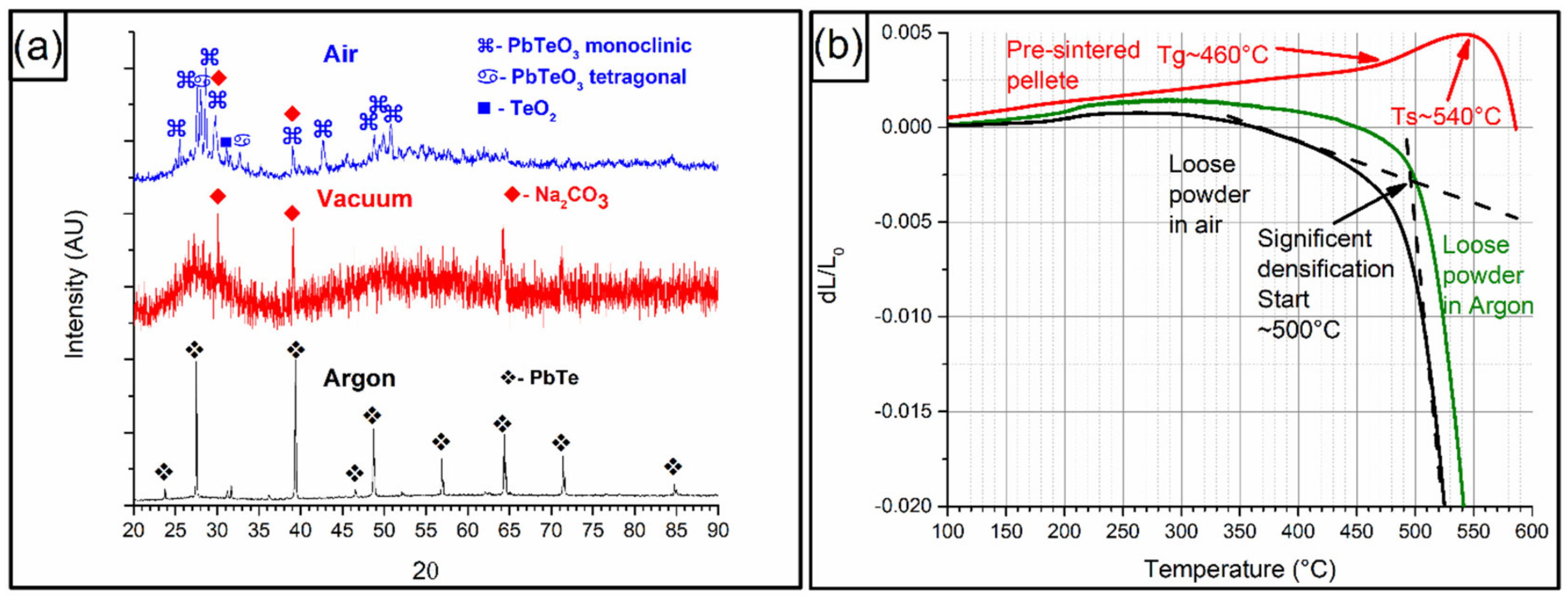
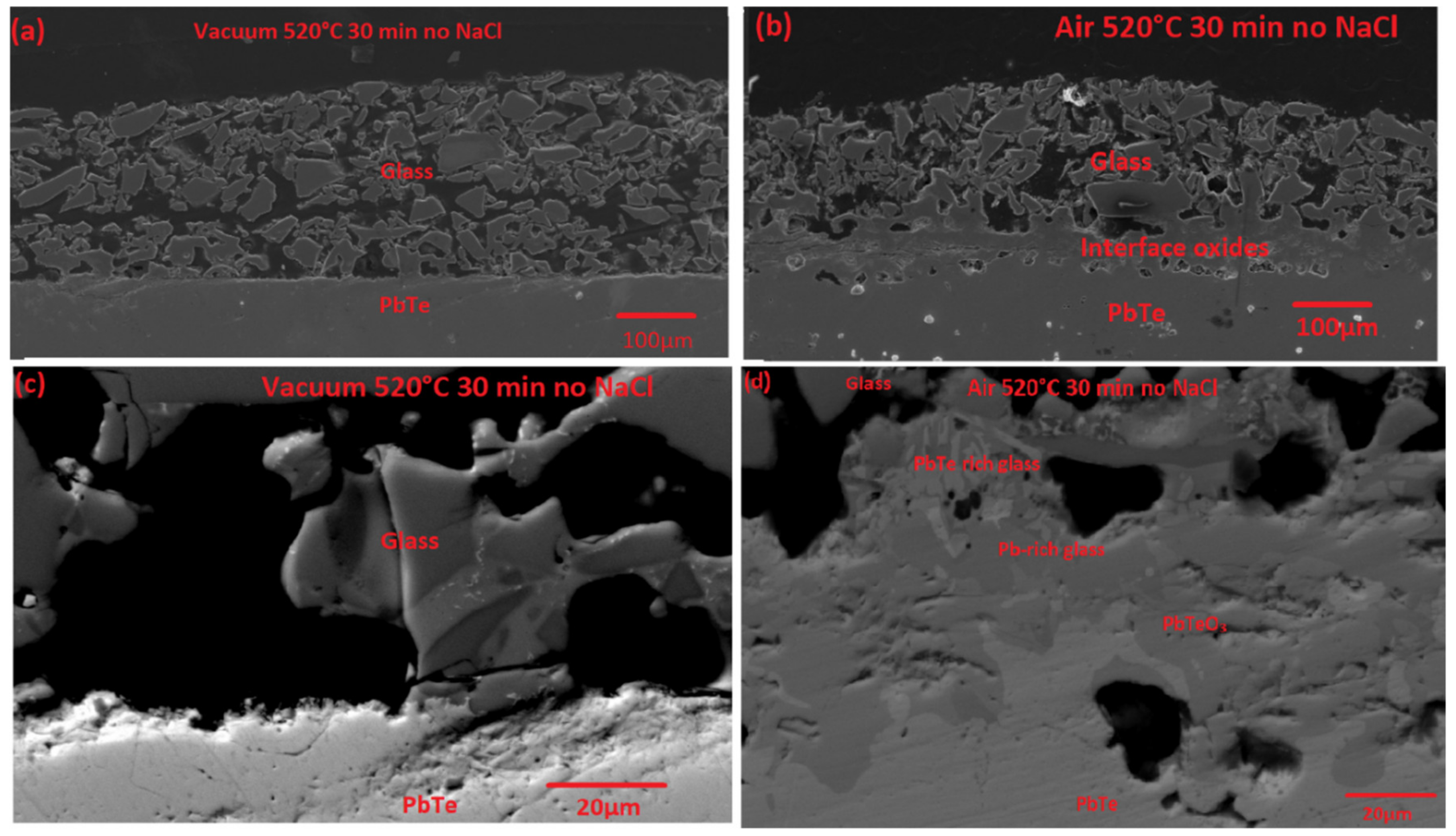
3.1. Atmosphere Optimization

The first attempt was carried out by coating the samples, letting them dry and then treating at 520 °C for 30 min in three different atmospheres. In Figure 2a, we can see the XRD results for the treatments under air, vacuum, and argon atmospheres. In all three, some measure of glass was detected with additional phases. The argon treated sample, marked black in the Figure, shows mainly PbTe in the XRD, indicating very little coverage of the glass. In addition, the coating had not adhered enough to make a cross section, with the glass immediately falling after coating. Upon vacuum treatment, shown in red, mainly glass was seen with a small amount of the Na2CO3 phase. This is common in Na containing glass powders [26] however since Na2CO3 can start decomposing above 400 °C into Na2O and CO2 [26,31], and can create some porosity during the coating process, which reaches 520 °C and gives rise to densification challenges.
The XRD following air atmosphere treatment (blue) indicates mainly glass and some PbTeO3 phases. Very small amounts of TeO2 can be seen, in addition to PbTeO3 in monoclinic and tetragonal phases [32]. This evidence is not straightforward, given that it the tetragonal phase was found to be stable only up to 485 °C in previous studies, which it changed to the monoclinic phase. This is further complicated as the monoclinic phase does not turn back into the tetragonal upon cooling. In addition, in the presence of water, the tetragonal is more stable. Whereas, in the absence of water, the monoclinic is more stable. It is understood that different phases are created in the heating/cooling step versus the isothermal step, with the monoclinic being formed at the high temperature isothermal stage and the tetragonal during heating and cooling. Nevertheless, the tetragonal phase is stable while the monoclinic is metastable after cooling.
Figure 2b shows the dilatometry of the glass powders treated in argon and air compared to a pre-sintered pellet which was produced for Tg and Ts measurements and sintered at 600 °C for 10 min. In this comparison it is interesting to see the relation between the sintering onset temperature vs. the glass transition temperature and the softening point of the glass. The glass transition (Tg) is the point where the sintered pellet changes its behavior from low expansion to high expansion. Whereas, the softening point (Ts) is the temperature where a change from expansion to contraction is obtained. This might be useful for understanding the observed behavior during the coating process. While at low temperatures expansion is expected, at higher temperatures densification can be seen by a large negative thermal expansion. It can be seen from Figure 2b that the onset of the densification starts much below Ts but it is mostly significant above Tg.
In addition, densification in air is initiated at ~10–15 °C lower temperatures compared to argon. This is supported by Bernardo et al. [20] showing that the effect is enhanced with increasing the Pb amount in the glass. This might be related to the multiple oxidation states of Pb, where the oxygen in the atmosphere allows a balance of the oxidation state of Pb.
The SEM images of the glass-coated PbTe, following a 520 °C/30 min. thermal treatments under vacuum and air atmospheres, are shown in Figure 3a–d, respectively. It can be seen that, while both coatings are porous, the air treatment resulted in a more interconnected coating. In addition, its bonding seems much better with a much wider interface. Using the EDS data, combined with the backscattered image of Figure 3c, no transition layer was detected following vacuum treatment. In contrast, as can be seen in Figure 3d, following the air treatment, a thick 50–100 µm interaction layer was observed. This layer is multi-phased, containing PbTe, Pb- rich glass with about the same amount of Pb and Si, and Pb- and Te-rich glasses with about 1:3 ratio of PbTeO3 and glass. The fact that both Pb- and Te-rich glass phases are apparent in this layer clearly indicates that the interaction occurs through the PbTe oxide (PbTeO3), detected also by the XRD (Figure 2a). However, the fact that most of the glass phases in the formed layer are Pb enriched (rather than Te enriched), can be explained by an oxidation of unreacted Te in the form of TeO2, that while not detected using EDS was seen in the XRD.
The formation of an interaction layer between the glass and the PbTe oxide phases, following air atmosphere treatment, poses both a solution and a challenge. The fact that there is an increase in coverage might be good, but the oxidation can adversely affect the thermoelectric sample. If the glass cover will occur quicker, a thinner oxidation layer will form and there will be less damage to the thermoelement, therefore, it is worth investigating a method of accelerating the densification, such as surfactants in the form of NaCl.

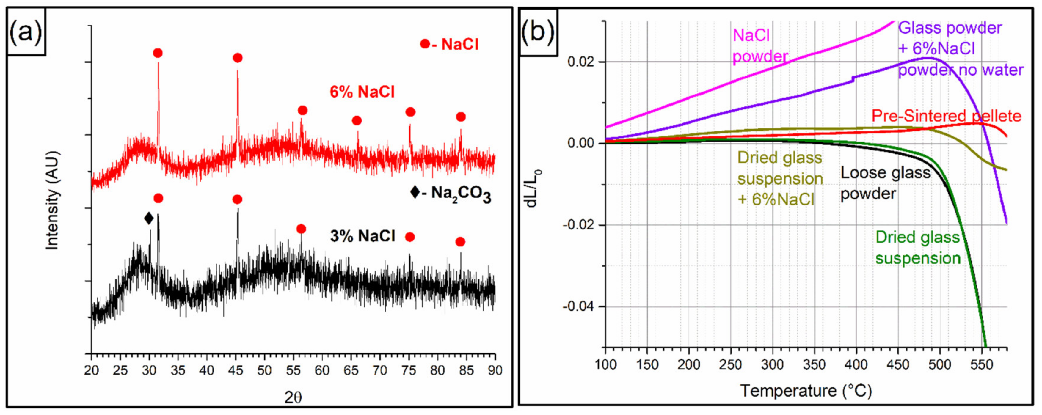
3.2. The Influence of Salt

The influence of NaCl on the coating can be seen in Figure 4 and Figure 5. In Figure 4a the XRD of the samples coated by glass with 3 wt. % and 6 wt. % NaCl can be seen. While both show mainly glass with NaCl impurities, it is interesting to note that some leftover Na2CO3 is present in the sample containing only 3% NaCl. Na2CO3 is known to decompose at lower temperatures with even 1% of NaCl was reported to lower the temperature by 80 °C [26]. The fact that with 3% NaCl, some Na2CO3 is still present, might indicate that the decomposition temperature was not lowered enough as opposed to the 6%. The presence of Na2CO3 is quite surprising, as while this is one of the constituents of the glass it is expected that in the melting process all CO2 would leave the system. This agrees with XRD results of the original glass [13]. However, it is possible that small amount of trapped residual CO2 react with small amounts of residual Na2O to recreate the compound.
It is also noteworthy that the fact that XRD characterization of this sample showed no PbTe or its oxides, implies that the coating coverage is truly full. In order to understand the significant improvement observed, different powders were analyzed by dilatometry in air as shown in Figure 4b for the following conditions; loose glass powder, to compare with Figure 2b; dried glass suspension, for understanding possible wetting effects of the powder on the densification; dried glass suspension containing 6% NaCl, to show the effect of the ionic strength of the Na+ and Cl ions; a mixture of glass and NaCl powders with no water, to investigate chemical effects of NaCl; NaCl only to gage the effect of salt; and a sintered pellet for reference of the expansion of a dense glass. While the effect of water on the reorganization of the glass powder was negligible (black vs. green samples), the salt with the water (yellow vs. green and black) greatly decreased the kinetics of the densification step. This can be explained by a better green density ahead of the densification process, allowing for a minimal densification to take place. This seems to be mostly attributed to the ionic strength of the solution, as the same result does not repeat with a mixture of dry glass and NaCl powders, containing no water (purple).
The yellow versus purple shows that the electrostatic effects of the Na+ and Cl in the suspension are more significant than the NaCl as a fining agent for Na2CO3 decomposition.
The SEM micrographs shown in Figure 5a–d show a much better coverage with both 3 and 6% NaCl, allowing a full coverage of the sample, in agreement with the XRD results. In Figure 5a,b it can be seen that while porosity is still present, there is no part in the layer where a full coverage isn’t achieved. Similarly, full contact with no visible cracks or interlayer indicates good bonding characteristics. A slightly better coverage is present in the 6% sample however this is largely the same. However, the backscattered images seen in Figure 5c for the 3% and 5d for the 6% show much more of the apparent mechanism and the phases. In Figure 5c three glass phases can be seen while in Figure 5d only two phases are seen. The lighter phase in both shows the presence of 3–5% Na and Cl and about 1% Te. In addition, the Si to Pb ratio changes to about 55% Si-45% Pb instead of 70% Si-30%Pb. The medium phase which exists in Figure 5c,d, shows the original glass with about 30% Pb and 70% Si with traces of Na and B. The dark phase which exists only in Figure 5c, or in the sample with 3 wt. % NaCl, contains about 2–3% Na with no Cl and a higher carbon contamination. This should be a glass phase with some Na2CO3 incorporated into it. This matches the fact that such a phase was detected by XRD for the 3 wt. % sample but not in the 6 wt. %. In both samples the lighter phase, which contains NaCl and higher Pb amount is abundant near the surface and disappears further away from it. This is a good indication that PbO plays a crucial role in the reaction with the NaCl. It is unclear why Te is missing and could be the result of TeO2 segregation as was suggested by the XRD in Figure 2a.
It can be seen that the NaCl has three distinct functions: (1) Lowering the electrostatic forces and allowing for higher density of the coated powder before densification as was seen by the dilatometry results; (2) promoting the interaction between the PbTeO3, and the glass to form a Pb-rich glass phase which covers the PbTe element; and (3) lowering (in the case of 3%) or eliminating (for 6%) the Na2CO3 by lowering the thermal decomposition temperature. With respect to the first two functions, both samples behaved similarly, the Na2CO3 elimination using 6% NaCl, was found as an important factor to prevent future degradation of the coating by decomposition of Na2CO3 and CO2 release.
While the 6 wt. % NaCl sample, treated at 520 °C for 30 min, show great promise, it is interesting to investigate the possibility of obtaining similar coating characteristics, even at lower temperatures or shorter time spans.

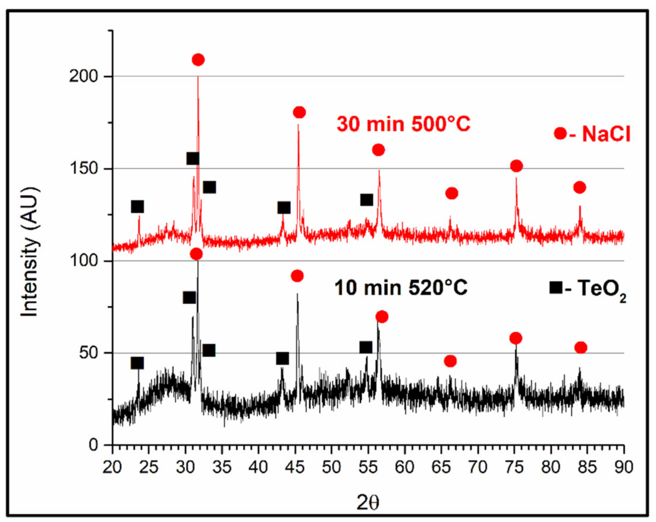
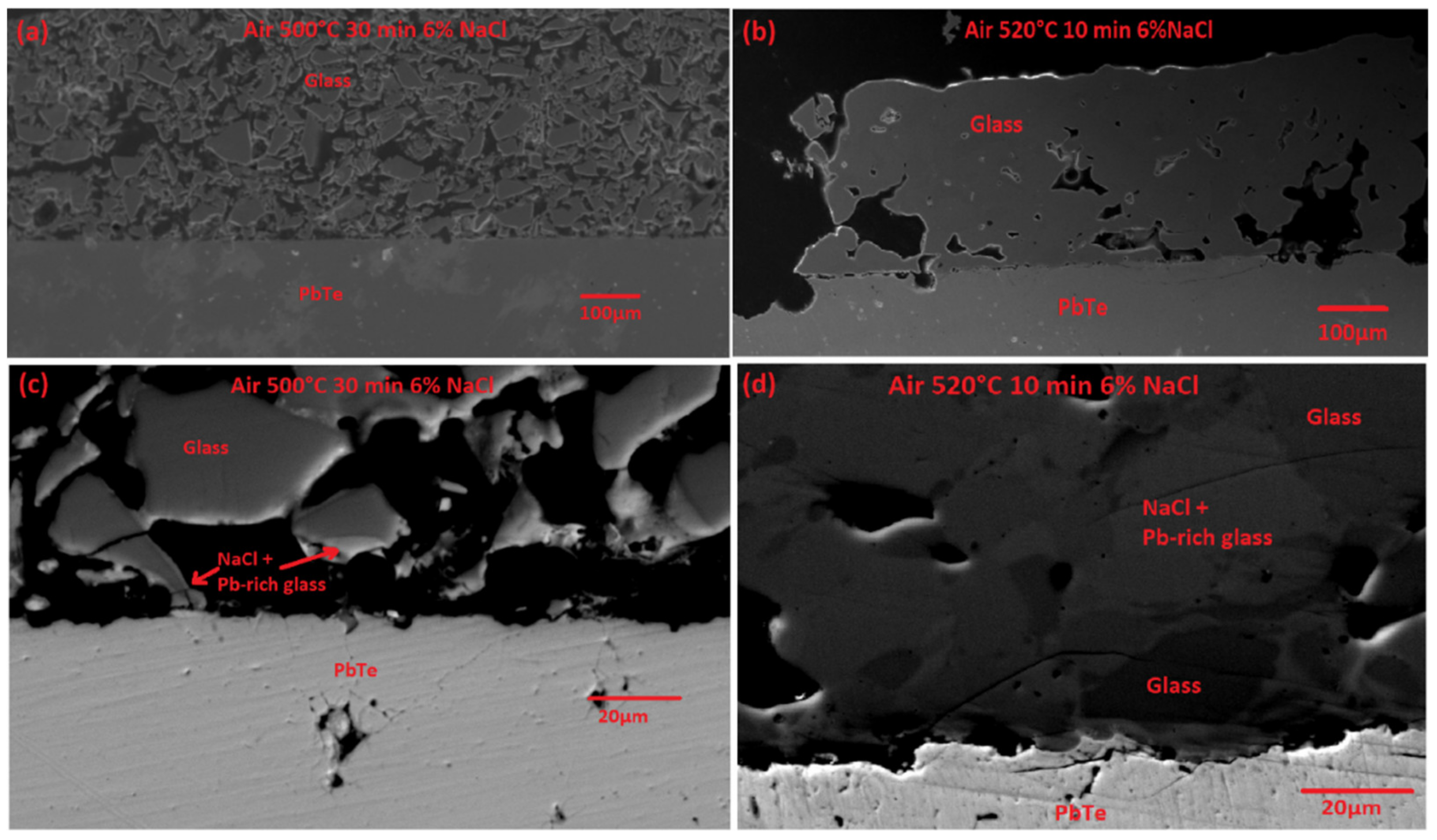
3.3. Time and Temperature of the Coating

Figure 6 shows the XRD following coating and subsequent thermal treatment at either a lower temperature (500 °C/30 min) or shorter duration (520 °C/10 min.) in air. Both samples show similar results with an appearance of both, the NaCl and TeO2 phases over the glassy phase. This shows that, while an incomplete cover without NaCl promotes PbTeO3 formation, in the presence of NaCl, the TeO2 formation is the resulting product with PbO joining the glass. TeO2 is only visible in samples with an incomplete coating due to the penetration depth of the x-rays in the XRD. Therefore, in both the air treated sample, containing no NaCl, and the samples treated at low temperature (500 °C) or short time (10 min), it was observed due to lack of coverage. In Figure 7a,b secondary electron images of the samples treated at a lower temperature of 500 °C; (a) and a shorter (10 min) duration (b) can be seen. The lower temperature resulted in an incomplete sintering, similar to what was seen in the vacuum treated sample, while the 10 min treated sample at 520 °C shows good sintering, but low bonding to the substrate, and therefore, an incomplete coverage. This might point to the fact that the latter observation, where some of the coating material was missed might have occurred during the sample preparation procedure, due to low bonding of the coating. There is a clear lack of adhesion between the coating and the sample, which is visible in the SEM micrographs, indicated by small voids between the coating and the base sample. During cutting and polishing of the cross-section samples, the lack of adhesion could result in loosing of some of the coating material.

3.4. Coating Mechanism

Based on the results shown above, the mechanism proposed for the coating is as follows. The glass suspension, coated over the PbTe, creates a low-density film during the drying process. This film increases in density where more ionic additives are available in the form of NaCl to break the electrostatic forces in the solution. This film is sintered well at temperatures of 520 °C, but not well enough below that. And the time required for adequate reaction with the PbTe substrate is 30 min. This is further improved when the PbTe is slightly oxidized, allowing a better wetting of the substrate. However, the glass reacts with the oxide, while creating a glass with a higher content of the PbO and TeO2 phases. This is mostly prevalent in areas containing the NaCl salt, as these areas show better spreading and coverage as well as higher PbO levels in the glass. Despite the oxidation, after the glass coverage, a very sharp coating interface can be seen for samples covered in the right conditions, showing that the oxidation is minimal and mitigated by the glass coating.

4. Conclusions

Glass coated PbTe samples were prepared using water suspended glass powder, which was brush painted and sintered on top of n-type PbTe samples. Various coating conditions were applied to understand the mechanisms and optimize the coating application for minimizing thermoelectric degradation, due to oxidation and volatile elements sublimation. The best coating atmosphere was air, where the interaction between a thin oxide layer on top of the PbTe sample and the glass formed the most stable interlayer. NaCl additions positively affected the coating coverage by increasing the ionic strength, preventing an interaction layer buildup, while promoting a reaction with a thin PbTeO3 layer, on top of the PbTe substrate, upon extracting the PbO into the glass and leaving behind TeO2. Additionally, NaCl helped lower the temperature of Na2CO3 decomposition and CO2 release.
A sintering temperature of 520 °C is needed for densification of the coating material, whereas 30 min are required to create a good adhesion to the PbTe sample. By optimizing these parameters, an adequate coating was applied on top of PbTe following air atmosphere thermal treatment at 520 °C for 30 min with a suspension including 6 wt. % of NaCl.

Author Contributions

Conceptualization, Y.S. and Y.G.; methodology, I.K.; formal analysis, Y.S.; investigation, Y.S.; writing—original draft preparation, Y.S.; writing—review and editing, Y.S. and Y.G.; visualization, Y.S.; supervision, Y.G.; funding acquisition, Y.G. All authors have read and agreed to the published version of the manuscript.

Funding

The work was supported by the Israel Science Foundation (ISF) Individual Research Grant No. 455/16.

Acknowledgments

One of authors, Yaniv Gelbstein holds the Samuel Ayrton Chair in Metallurgy. The authors would like to thank Dima Mogilyansky for the XRD analysis Hagit Didi for the SEM results and Yair George for the preparation of the thermoelectric samples.

Conflicts of Interest

The authors declare no conflict of interest.

References

  1. Sadia, Y.; Ohaion-Raz, T.; Ben-Yehuda, O.; Korngold, M.; Gelbstein, Y. Criteria for extending the operation periods of thermoelectric converters based on IV-VI compounds. J. Solid State Chem. 2016, 241, 79–85. [Google Scholar] [CrossRef]
  2. Wang, Z.L.; Araki, T.; Onda, T.; Chen, Z.C. Effect of annealing on microstructure and thermoelectric properties of hot-extruded Bi–Sb–Te bulk materials. J. Mater. Sci. 2018, 53, 9117–9130. [Google Scholar] [CrossRef]
  3. Zhao, D.; Tian, C.; Liu, Y.; Zhan, C.; Chen, L. High temperature sublimation behavior of antimony in CoSb3 thermoelectric material during thermal duration test. J. Alloys Compd. 2011, 509, 3166–3171. [Google Scholar] [CrossRef]
  4. Bux, S.K.; Yeung, M.T.; Toberer, E.S.; Snyder, G.J.; Kaner, R.B.; Fleurial, J.P. Mechanochemical synthesis and thermoelectric properties of high quality magnesium silicide. J. Mater. Chem. 2011, 21, 12259–12266. [Google Scholar] [CrossRef]
  5. LaLonde, A.D.; Pei, Y.; Snyder, G.J. Reevaluation of PbTe1−xIx as high performance n-type thermoelectric material. Energy Environ. Sci. 2011, 4, 2090–2096. [Google Scholar] [CrossRef] [Green Version]
  6. Sadia, Y.; Ben-Ayoun, D.; Gelbstein, Y. Evaporation–condensation effects on the thermoelectric performance of PbTe-based couples. Phys. Chem. Chem. Phys. 2017, 19, 19326–19333. [Google Scholar] [CrossRef]
  7. Ben-Ayoun, D.; Sadia, Y.; Gelbstein, Y. High temperature thermoelectric properties evolution of Pb1-xSnxTe based alloys. J. Alloys Compd. 2017, 722, 33–38. [Google Scholar] [CrossRef]
  8. Eggers, P.; Mueller, J.; Kortier, W. Thermoelectric Module. No. US 4211889, 8 July 1980. [Google Scholar]
  9. Nieroda, P.; Mars, K.; Nieroda, J.; Leszczyński, J.; Król, M.; Drożdż, E.; Jeleń, P.; Sitarz, M.; Koleżyński, A. New high temperature amorphous protective coatings for Mg2Si thermoelectric material. Ceram. Int. 2019, 45, 10230–10235. [Google Scholar] [CrossRef]
  10. Leszczyński, J.; Nieroda, P.; Nieroda, J.; Zybała, R.; Król, M.; Łącz, A.; Kaszyca, K.; Mikuła, A.; Schmidt, M.; Sitarz, M.; et al. Si-OC amorphous coatings for high temperature protection of In0.4Co4Sb12 skutterudite for thermoelectric applications. J. Appl. Phys. 2019, 125, 215113. [Google Scholar] [CrossRef]
  11. Park, S.H.; Kim, Y.; Yoo, C.Y. Oxidation suppression characteristics of the YSZ coating on Mg2Si thermoelectric legs. Ceram. Int. 2016, 42, 10279–10288. [Google Scholar] [CrossRef]
  12. El-Genk, M.S.; Saber, H.H.; Caillat, T.; Sakamoto, J. Tests results and performance comparisons of coated and un-coated skutterudite based segmented unicouples. Energy Convers. Manage. 2006, 47, 174–200. [Google Scholar] [CrossRef]
  13. Sadia, Y.; Ben-Ayoun, D.; Gelbstein, Y. PbO–SiO2-based glass doped with B2O3 and Na2O for coating of thermoelectric materials. J. Mater. Res. 2019, 34, 3563–3572. [Google Scholar] [CrossRef]
  14. Hotza, D.P.; Greil, P. Aqueous tape casting of ceramic powders. Mater. Sci. Eng. A 1995, 202, 206–217. [Google Scholar] [CrossRef]
  15. Baino, F.; Vitale-Brovarone, C. Feasibility of glass–ceramic coatings on alumina prosthetic implants by airbrush spraying method. Ceram. Int. 2015, 41, 2150–2159. [Google Scholar] [CrossRef] [Green Version]
  16. Bretcanu, O.; Verné, E.; Borello, L.; Boccaccini, A.R. Boccaccini. Bioactivity of degradable polymer sutures coated with bioactive glass. J. Mater. Sci. - Mater. Med. 2004, 15, 893–899. [Google Scholar] [CrossRef]
  17. Gordon, R. Chemical vapor deposition of coatings on glass. J. Non-Cryst. Solids 1997, 218, 81–91. [Google Scholar] [CrossRef]
  18. Butt, M.A.; Chughtai, A.; Ahmad, J.; Ahmad, R.; Majeed, U.; Khan, I. Theory of adhesion and its practical implications. J. Faculty Eng. Tech. 2008, 2007, 21–45. [Google Scholar]
  19. Yong-Taeg, O.; Fujino, S.; Morinag, K. Fabrication of transparent silica glass by powder sintering. Sci. Technol. Adv. Mater. 2002, 3, 297–301. [Google Scholar] [CrossRef]
  20. Bernardo, E.; Scarinci, G.; Hreglich, S.; Zangiacomi, G. Effect of time and furnace atmosphere on the sintering of glasses from dismantled cathode ray tubes. J. Eur. Ceram. Soc. 2007, 27, 1637–1643. [Google Scholar] [CrossRef]
  21. Jeong, J.A.; Jeon, Y.J.; Kim, S.S.; Kim, B.K.; Chung, K.B.; Kim, H.K. Simple brush-painting of Ti-doped In2O3 transparent conducting electrodes from nano-particle solution for organic solar cells. Sol. Energy Mater. Sol. Cells 2014, 122, 241–250. [Google Scholar] [CrossRef]
  22. Jurak, M.; Chibowski, E. Wettability and topography of phospholipid DPPC multilayers deposited by spin-coating on glass, silicon, and mica slides. Langmuir 2007, 23, 10156–10163. [Google Scholar] [CrossRef] [PubMed]
  23. Lowen, W.K.; Broge, E.C. Effects of dehydration and chemisorbed materials on the surface properties of amorphous silica. J. Phys. Chem. 1961, 65, 16–19. [Google Scholar] [CrossRef]
  24. Hujova, M.; Vernerova, M. Influence of fining agents on glass melting: a review, part 1. Ceram. Silik. 2017, 61, 119–126. [Google Scholar] [CrossRef] [Green Version]
  25. Hong, K.S.; Speyer, R.F. Thermal Analysis of Reactions in Soda–Lime Silicate Glass Batches Containing Melting Accelerants: I, One-and Two-Component Systems. J. Am. Ceram. Soc. 1993, 76, 598–604. [Google Scholar] [CrossRef]
  26. Hong, K.S.; Lee, S.W.; Speyer, R.F. Thermal Analysis of Reactions in Soda–Lime Silicate Glass Batches Containing Melting Accelerants: II, Multicomponent Systems. J. Am. Ceram. Soc. 1993, 76, 605–608. [Google Scholar] [CrossRef]
  27. Pagnoux, C.; Chartier, T.; de Granja, M.F.; Doreau, F.; Ferreira, J.M.; Baumard, J.F. Aqueous suspensions for tape-casting based on acrylic binders. J. Eur. Ceram. Soc. 1998, 18, 241–247. [Google Scholar] [CrossRef]
  28. Frieser, R.G. A review of solder glasses. Act. Passive Electron. Compon. 1975, 2, 163–199. [Google Scholar] [CrossRef] [Green Version]
  29. Ateş, A.; Önen, U.; Ercenk, E.; Yılmaz, Ş. Crystallization Behaviors and Seal Application of Basalt Based Glass-Ceramics. In Proceedings of the AIP Conference, Istanbul, Turkey, 1–3 June 2016; Volume 1809, p. 020006. [Google Scholar]
  30. De Sanctis, O.; Gomez, L.; Pellegri, N.; Parodi, C.; Marajofsky, A.; Duran, A. Protective glass coatings on metallic substrates. J. Non-Cryst. Solids 1990, 121, 338–343. [Google Scholar] [CrossRef]
  31. Siriwardane, R.V.; Poston Jr, J.A. Effect of additives on decomposition of sodium carbonate: Precombustion CO2 capture sorbent regeneration. Energy Fuels 2011, 25, 1284–1293. [Google Scholar] [CrossRef]
  32. Young, I.M. The central region of the PbO/TeO2 phase diagram. J. Mater. Sci. 1979, 14, 1579–1585. [Google Scholar] [CrossRef]
Figure 1. Some of the challenges in turning thermoelectric devices into generators. In red the challenges of sublimation and oxidation are marked, with the hot-side of the element showing sublimation. A suggested coating is marked in a dashed red line.
Metals 10 00284 g001
Figure 2. (a) XRD patterns of the coated samples, following 520 °C/30 min. thermal treatment under argon (black), vacuum (red) and air (blue) atmospheres. (b) Dilatometry measuremnts of the glass powder in air (black) and argon (green) with a pre-sintered pellete (red) as reference, showing densification at lower temperatures in air and that densification is expected at a little above 500 °C.
Metals 10 00284 g002
Figure 3. (a) SEM micrographs of glass coated PbTe, following 520 °C/30 min. thermal treatment under vacuum (a,c) and air (b,d) atmospheres. (a,b) are secondary electrons images while (c,d) are back scattered electrons images.
Metals 10 00284 g003
Figure 4. (a) XRD patterns of the coated samplesupon addition of 3 wt. % (black) and 6 wt. % NaCl (red). (b) Dilatometry measuremnts following different factors variation; black and red are glass in air and pre-sintered pellete redrawn from Figure 2b for a comperison; Dried glass suspention (green); dried glass suspension with 6% NaCl (yellow); glass powder with NaCl powder and no water (purple) and NaCl powder only (pink).
Metals 10 00284 g004
Figure 5. Scanning electron microscopy (SEM) micrographs of glass coated PbTe, following 3 wt. % (a,c) and 6 wt. % (b,d) NaCl addition. (a,b) are secondary electrons images while (c,d) are back scattered electrons images.
Metals 10 00284 g005
Figure 6. X-ray diffraction (XRD) patterns of the coated samples following thermal treatments of 500 °C for 30 min (Red) and 520 °C for 10 min (Black).
Metals 10 00284 g006
Figure 7. SEM micrographs following coating and subsequent thermal treatment at either a lower temperature of 500 °C (a,c) or shorter duration of 10 min. (b,d), compared to the previously applied 520 °C/30 min. condition. (a,b) are secondary electrons images while (c,d) are back scattered electrons images.
Metals 10 00284 g007
Table 1. The various coating conditions applied in the current research, with bold marking the variable that is changed in the experiment, including thermal treatment’s temperature, time and atmosphere as well as the amount of NaCl added to the glass suspension.
SampleTemperatureTime (min)wt. % NaClAtmosphere
1-1520 °C300Air
1-2520 °C300Argon
1-3520 °C300Vacuum
2-1520 °C303%Air
2-2520 °C306%Air
3-1520 °C106%Air
3-2500 °C306%Air

