Examination of Behavior from Selected Foundry Sands with Alkali Silicate-Based Inorganic Binders

 ,
, 
 and
and
Abstract
1. Introduction
2. Work Methodology and Materials
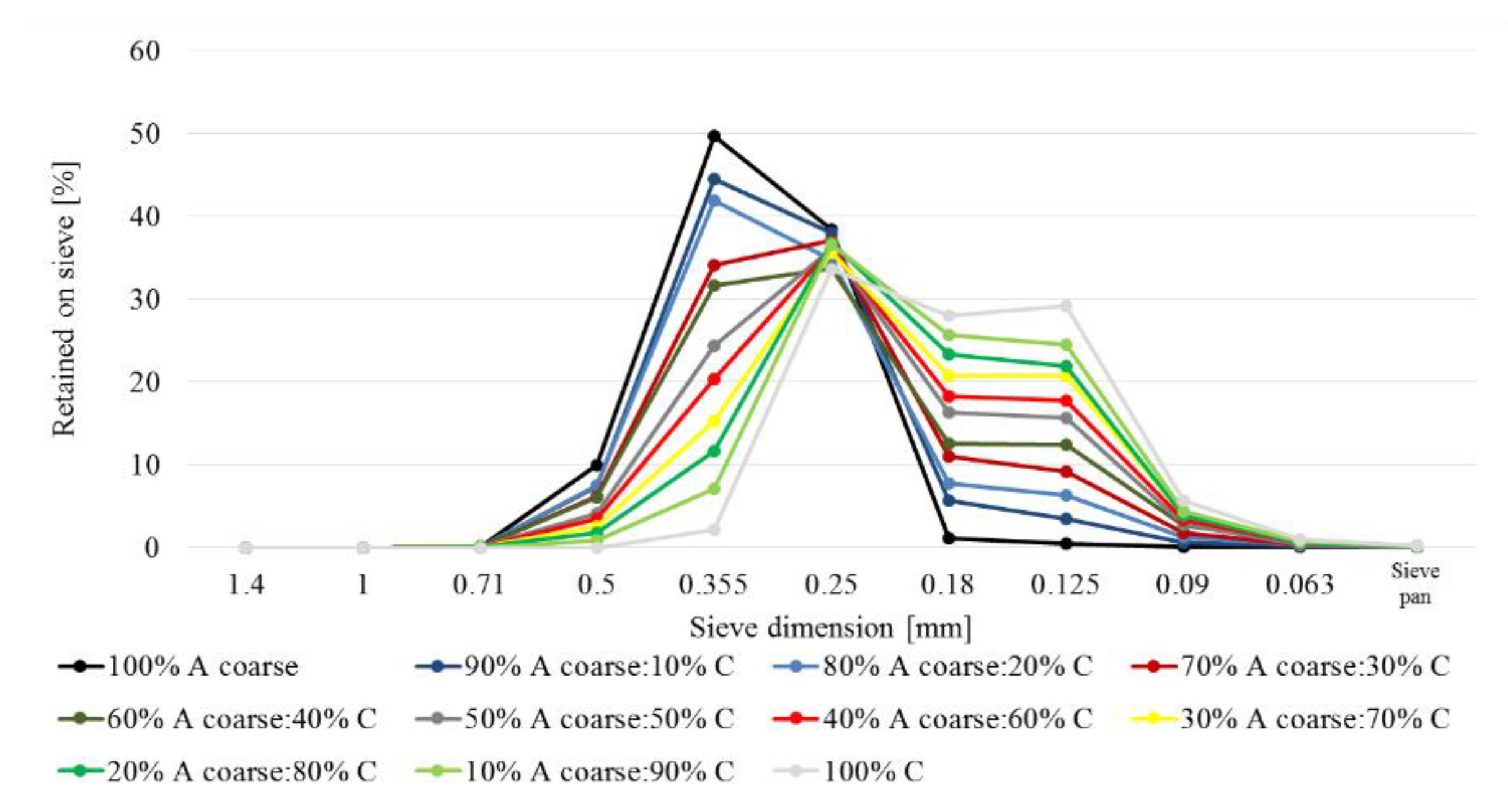
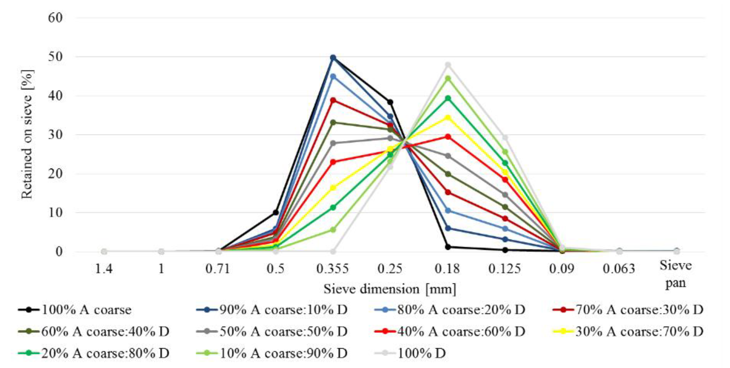
2.1. Sieve Analysis
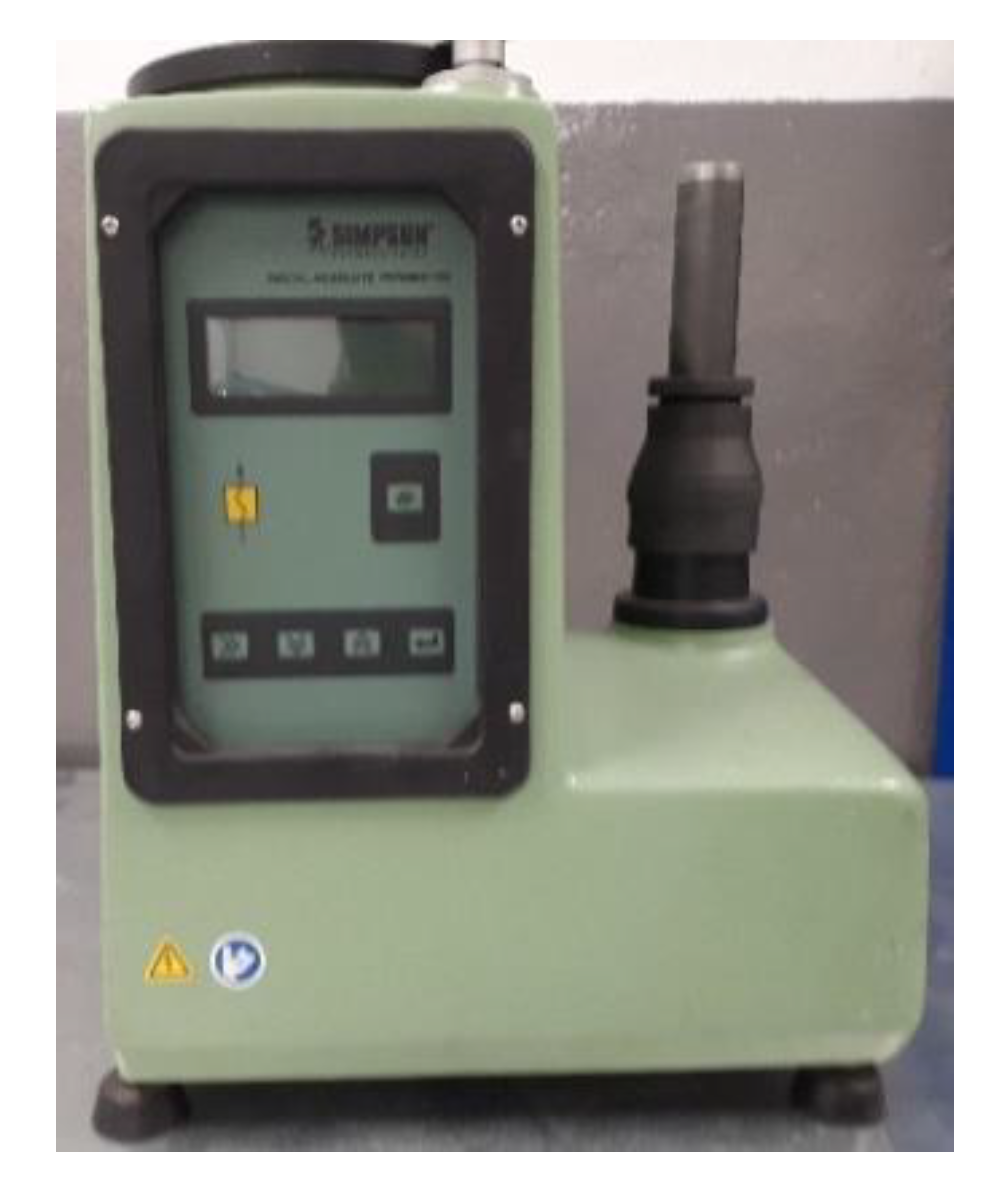
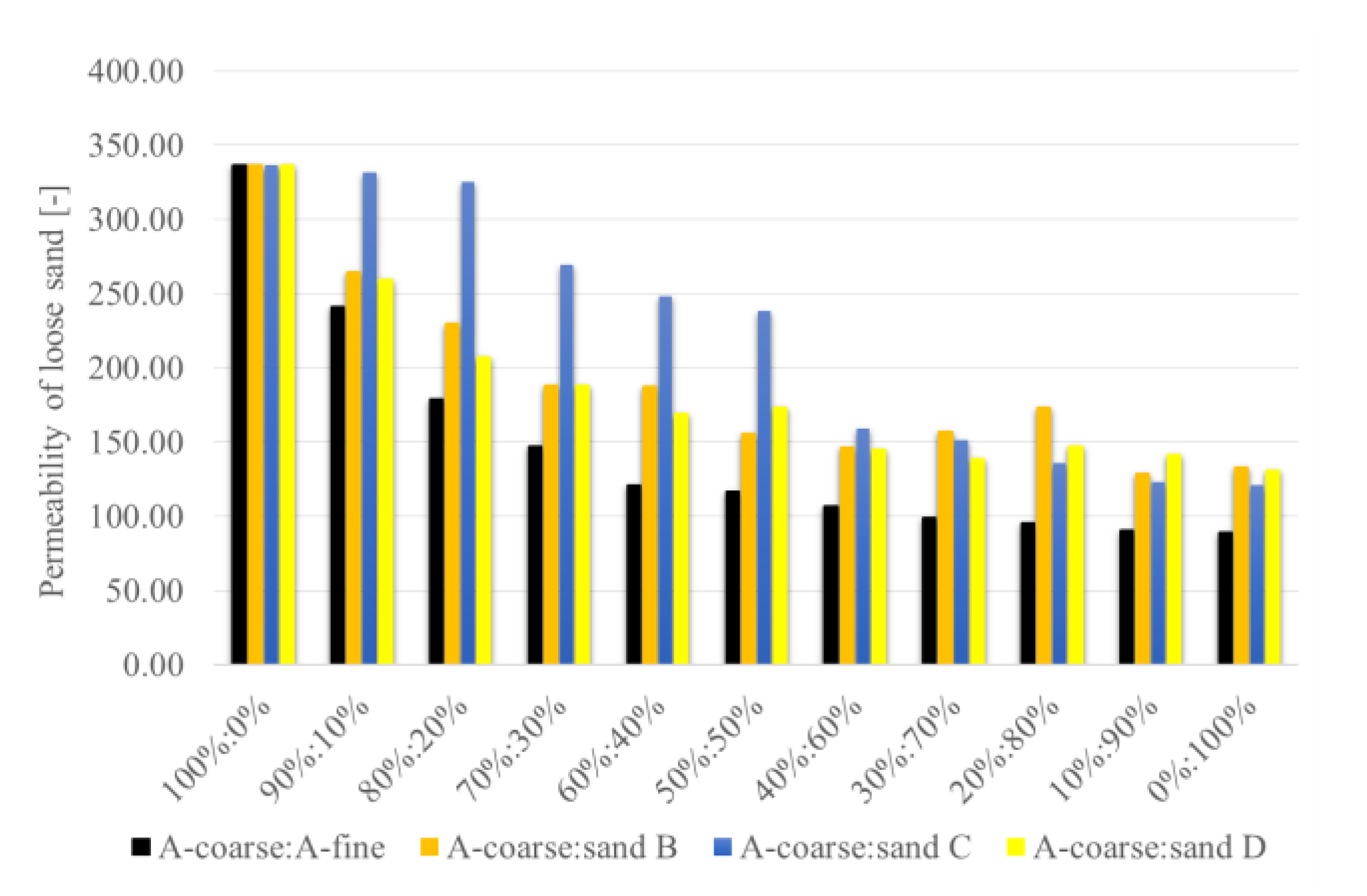
2.2. Permeability Measurement
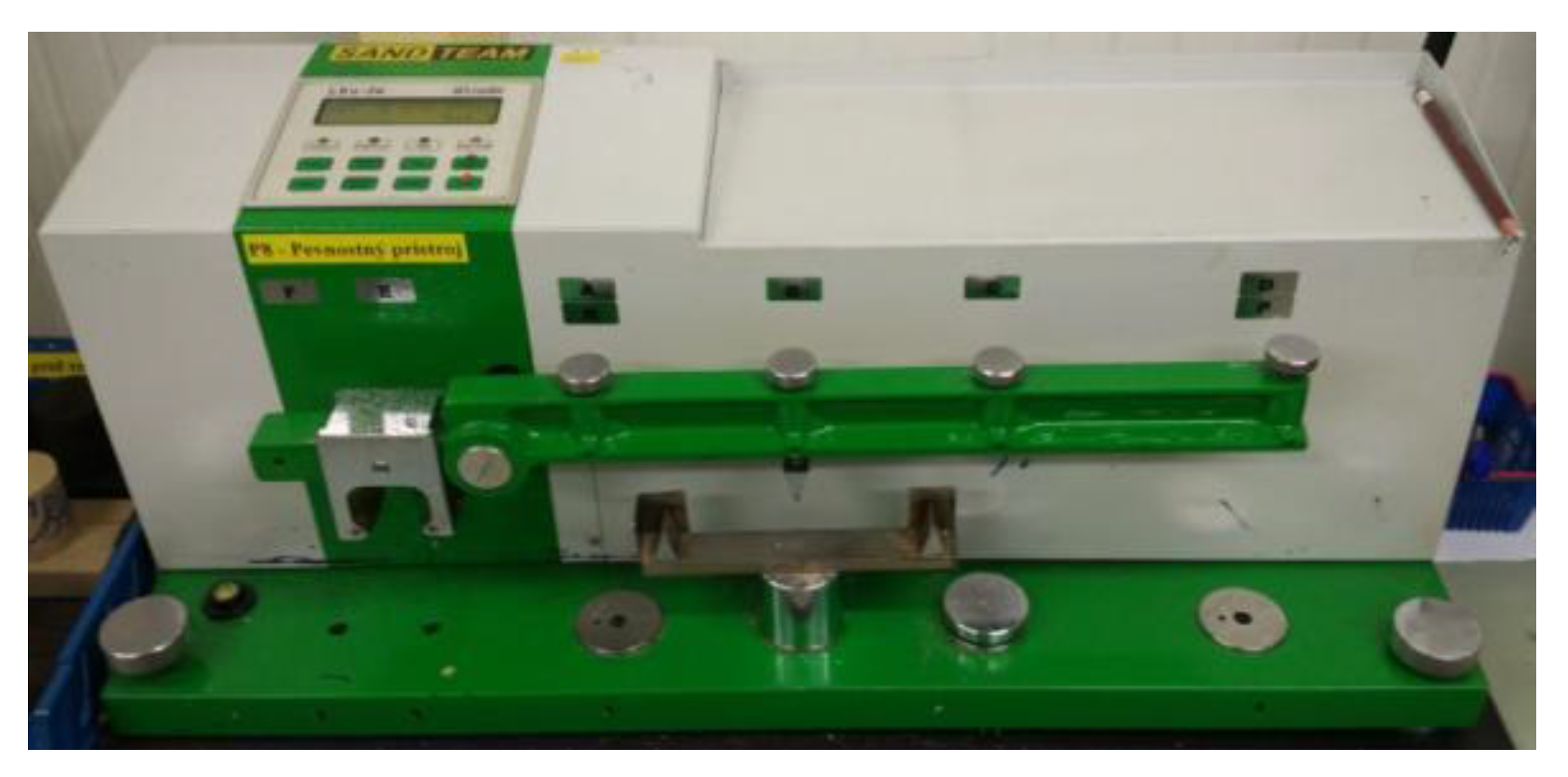
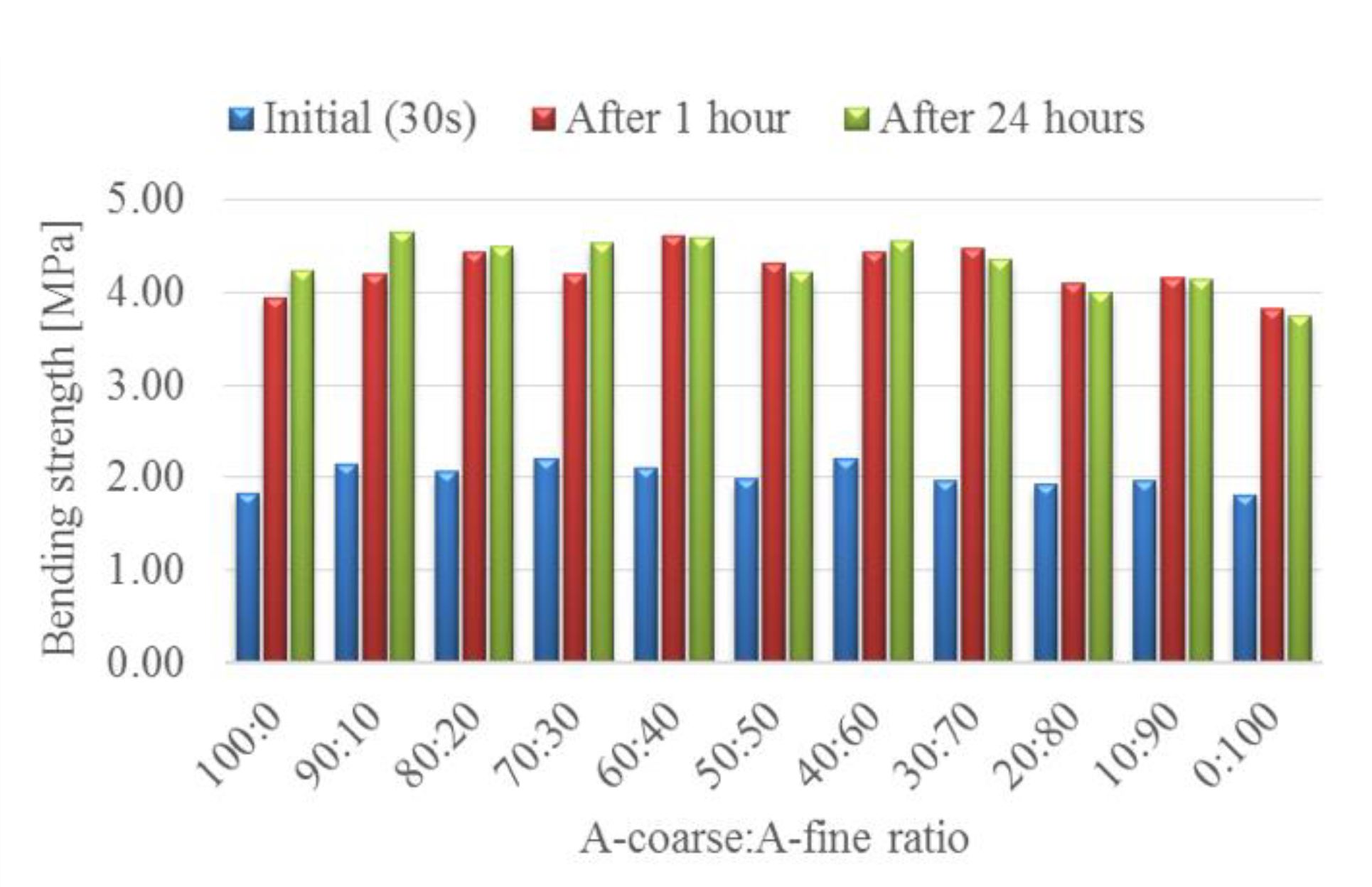
2.3. Bending Strength
- Dry mixing of sands for 60 s;
- Dry mixing of sands with powder additive for 60 s;
- Mixing with liquid part of binder for 60 s;
- Storage of prepared mixture in closeable container in order to prevent drying during samples production.
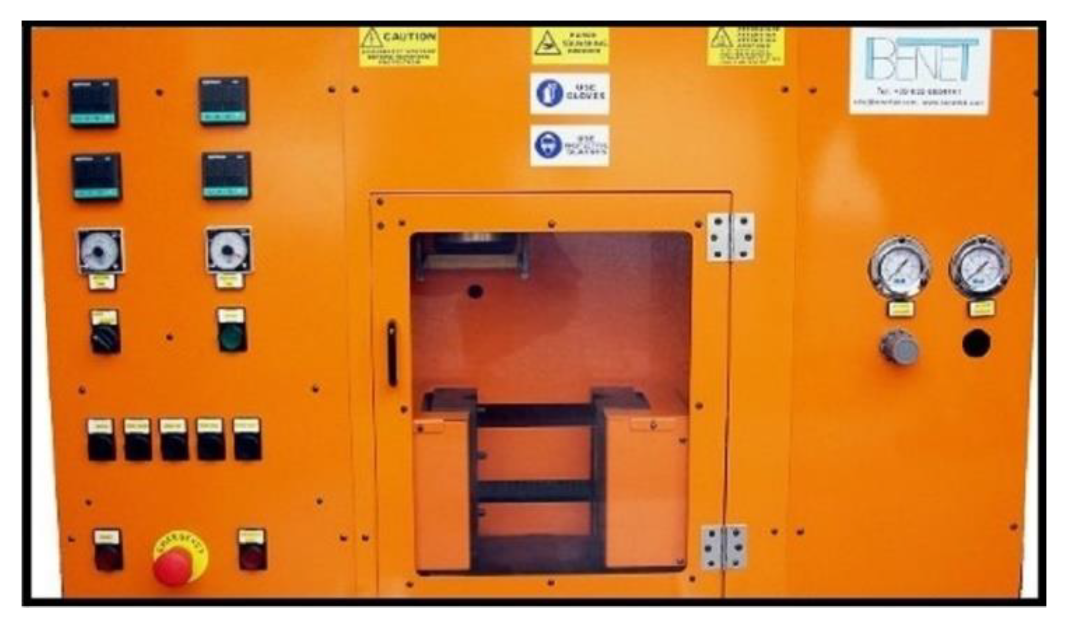
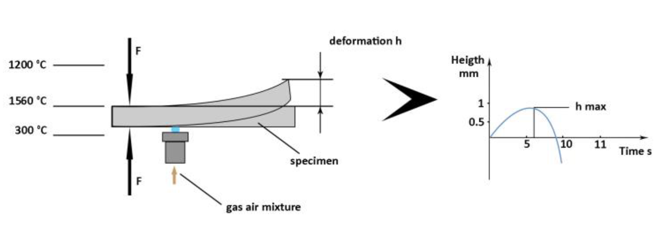
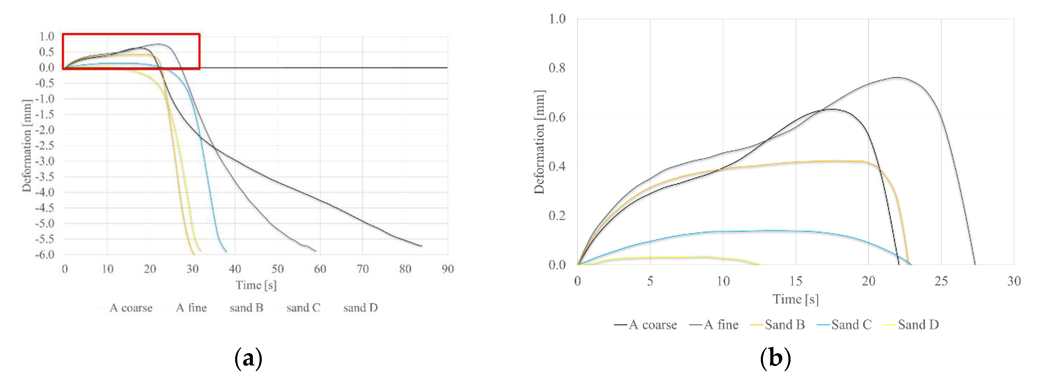
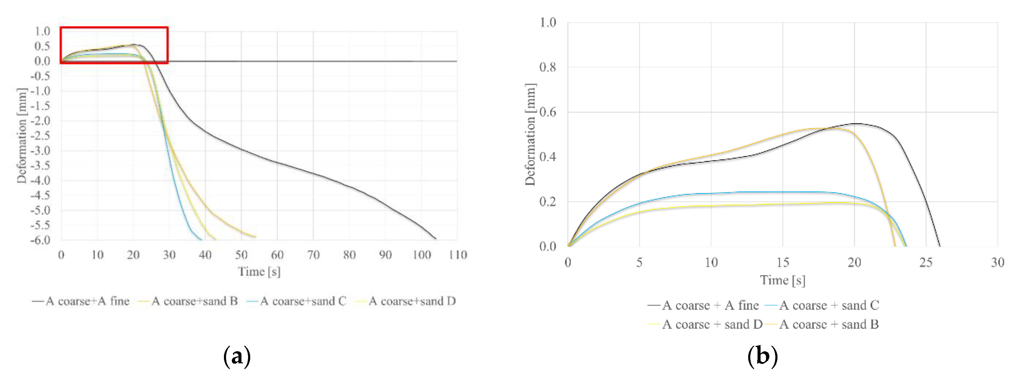
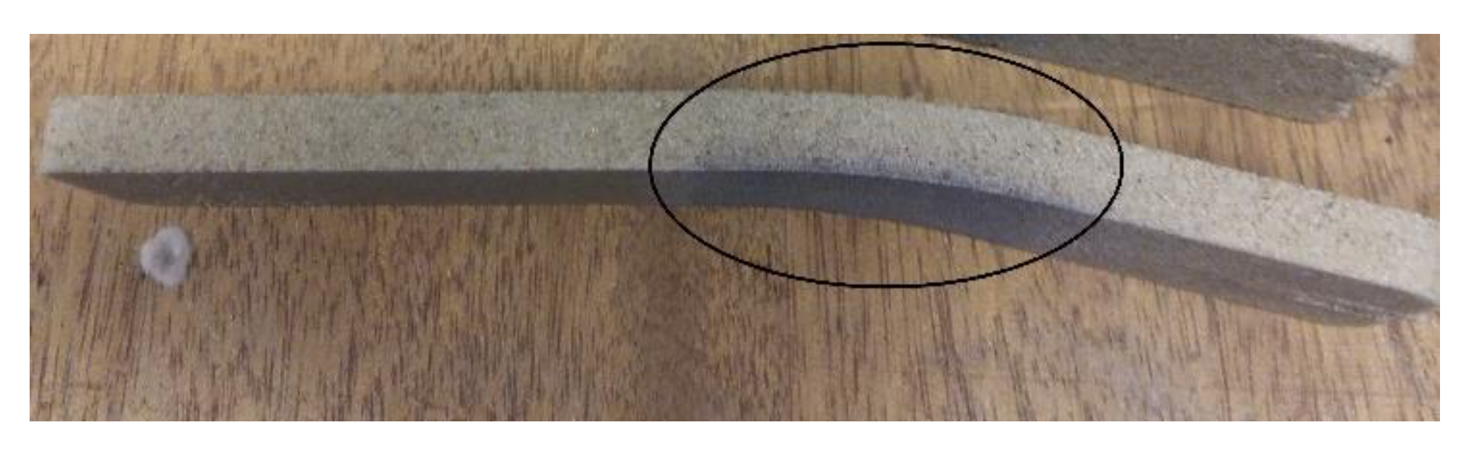
2.4. Hot Distortion Test
- Core box temperature 150 °C with 30 s curing time.
3. Results
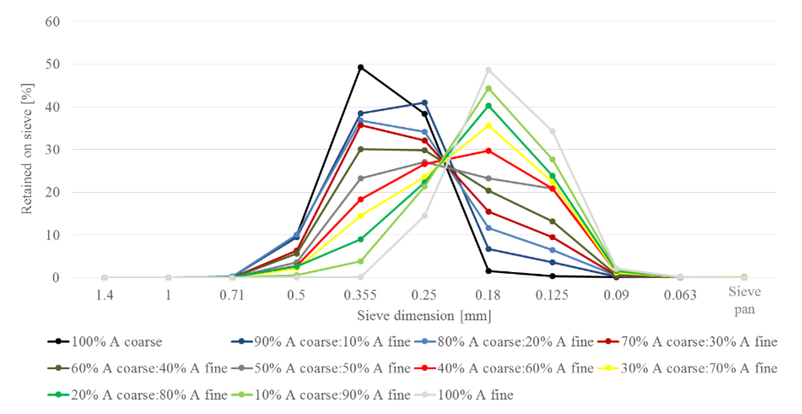
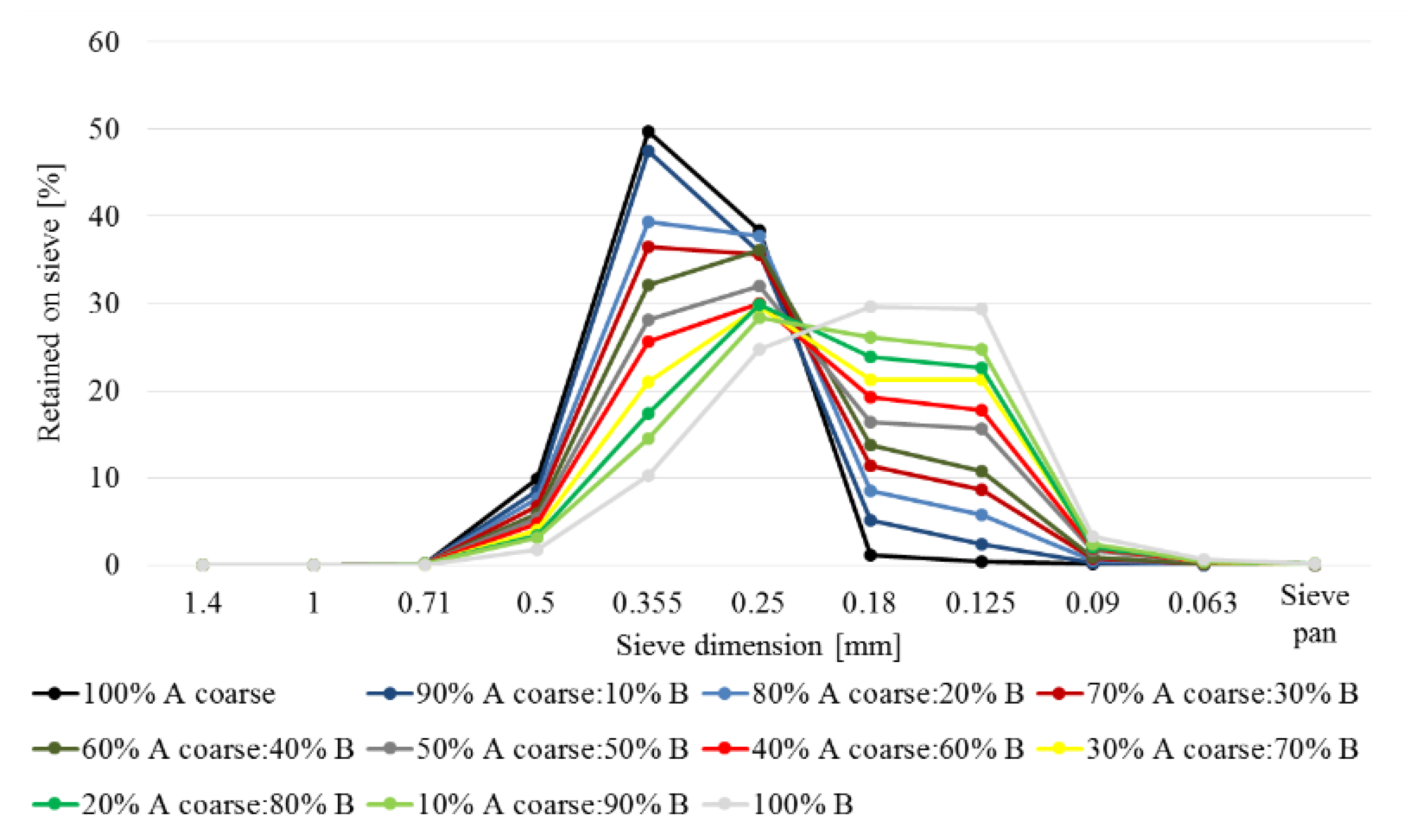
3.1. Sieve Analysis
3.2. Permeability of Loose Sand
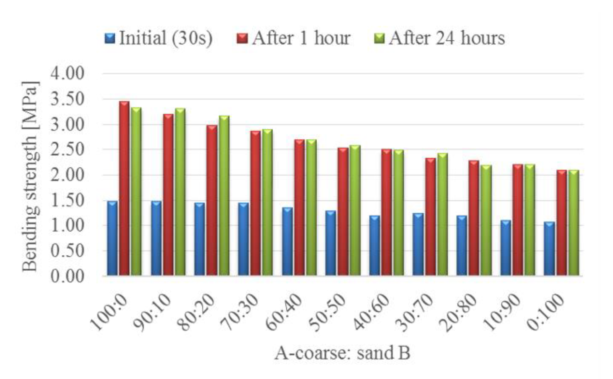
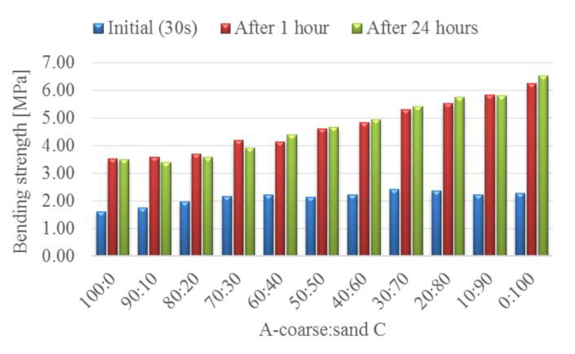
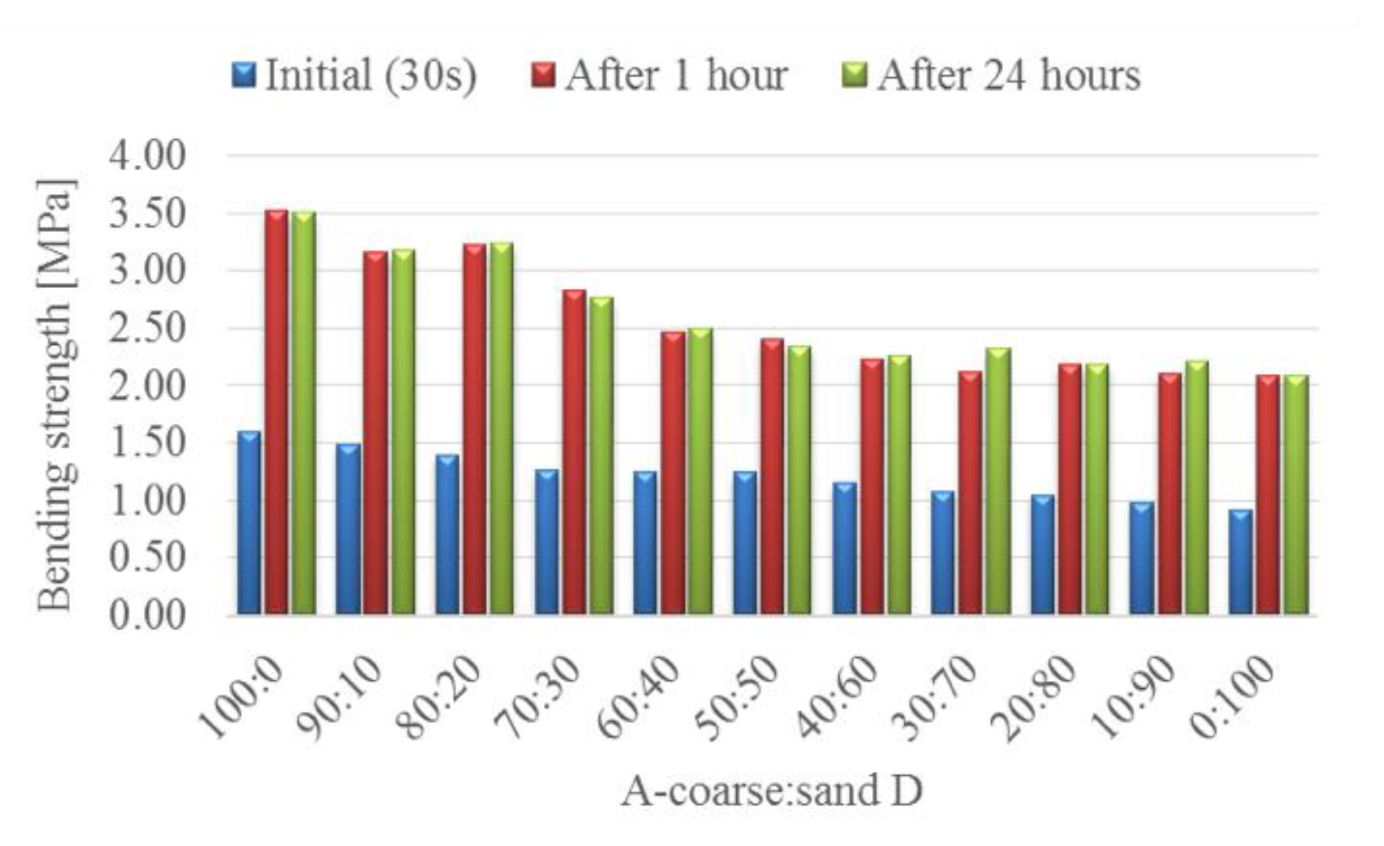
3.3. Bending Strength
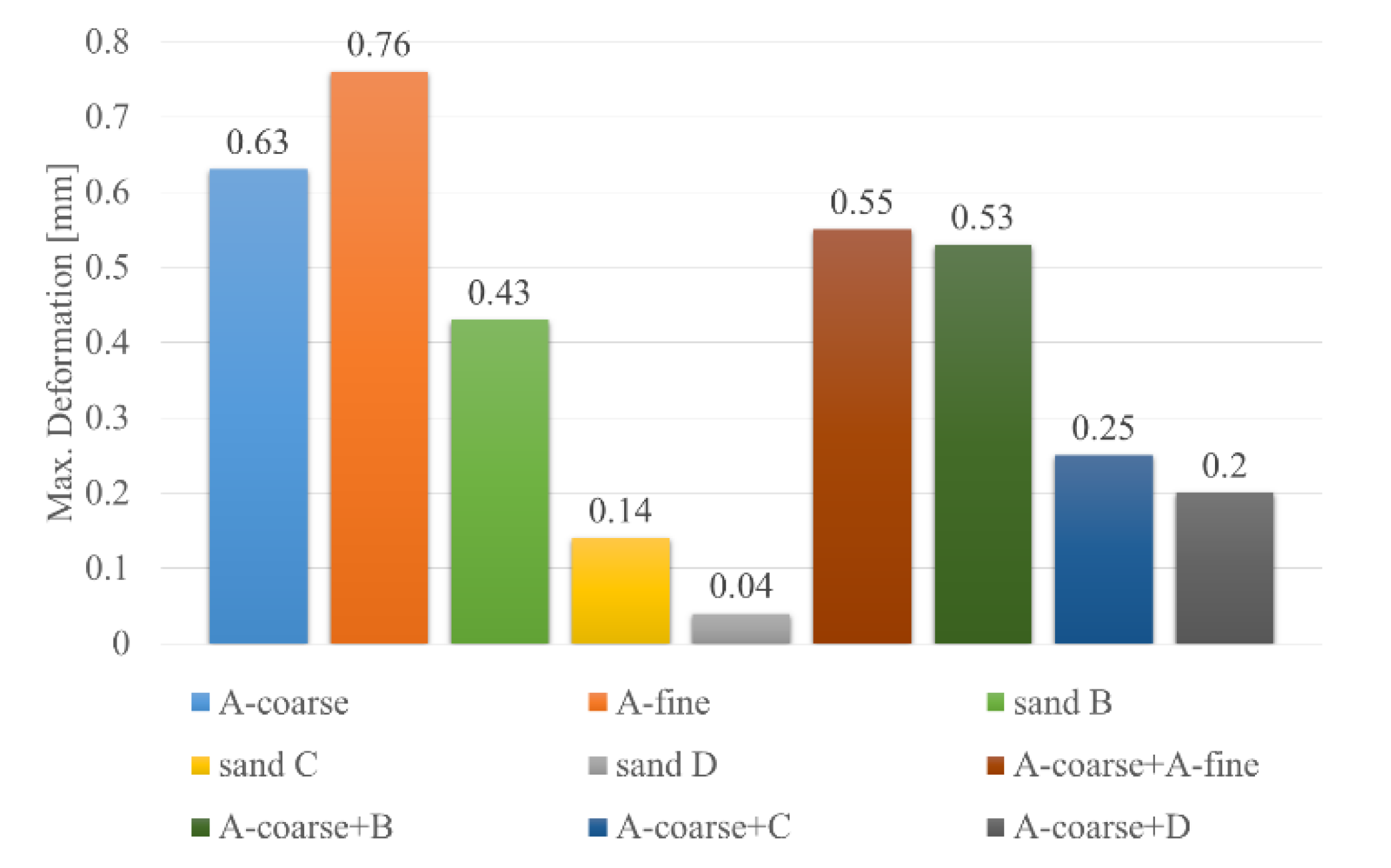
3.4. Hot Distortion Test
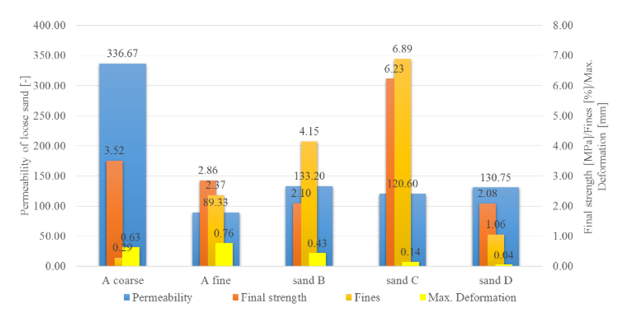
4. Summary and Conclusions
- Adding A fine resulted in the largest decrease of permeability, non-linear strength behavior, minor decrease of maximal deformation, and maximizing the thermoplastic bending behavior of A coarse;
- Addition of B caused a decrease of permeability and strength and a minor decrease of maximal deformation;
- Introducing C into A coarse had a minor effect on the drop of permeability up to 50% addition, bending strength increased significantly, and maximal deformation was reduced;
- Addition of D led to nearly the same decrease of permeability and bending strength as with B, but maximal deformation was the lowest with this sand.
Author Contributions
Funding
Conflicts of Interest
References
- Polzin, H. Inorganic Binders for Mould and Core Production in the Foundry; Schiele & Schön GmbH: Berlin, Germany, 2014; pp. 146–149. [Google Scholar]
- Jelínek, P. Disperzní Soustavy Slévárenských Formovacích Směsí: Ostřiva; Technical University of Ostrava: Ostrava, Czechia, 2000; pp. 10–15. [Google Scholar]
- Krishnamoorthy, A. Sand Control Practice in Ferrous Foundries; Indian Institute of Foundrymen: Kolkata, India, 1991; pp. 43–46. [Google Scholar]
- Iden, F.; Tilch, W.; Wojtas, H. Die Haftungsmechanismen von Cold-Box-Bindemitteln auf der Formstoffoberfläche. Giesserei 2011, 98, 24–36. [Google Scholar]
- Polzin, H. Die Verfestigung von Alternativen Formgrundstoffen mit Anorganischen Bindersystemen. Available online: http://www.umweltstiftung.de/media/0405101027413fou.pdf (accessed on 16 December 2019).
- Brown, R. Foseco Ferrous Foundrymen Handbook; Butterworth Heinneman: Oxford, UK, 2000; pp. 146–166. [Google Scholar]
- Zaretskiy, L. Modified Silicate Binders New Developments and Applications. Int. J. Met. 2016, 10, 88–99. [Google Scholar] [CrossRef]
- Banganayi, F.C.; Nyembwe, K.; Polzin, H. Effects of South African Silica Sand Properties on the Strength Development and Collapsibility of Single Component Sodium Silicate Binders. Arch. Foundry Eng. 2017, 17, 5–12. [Google Scholar] [CrossRef][Green Version]
- Conev, M.; Vasková, I.; Hrubovčáková, M.; Hajdúch, P. Impact of Silica Sand Granulometry on Bending Strength of Cores Produced by ASK Inotec Process. Manuf. Technol. 2016, 16, 327–334. [Google Scholar]
- Ábelová, M.; Maglay, J. Viate piesky Záhorskej nížiny. Enviromagazín 2008, 13, 26–27. (In Czech) [Google Scholar]
- Sklopísek Střeleč, A.S. Catalogue of Products. Available online: https://en.glassand.eu/our-sands/by-type/foundry-sands (accessed on 16 December 2019).
- LKAB Minerals. Small Beads, Big Impact. Available online: https://www.lkabminerals.com/en/minsand-cheaper-than-zircon/ (accessed on 16 December 2019).
- Recknagel, U.; Dahlmann, M. Special Sands-Base Materials for Modern Core and Mould Making. Giess.-Rundsch. 2009, 56, 6–17. [Google Scholar]
- Wakita, K.; Matsubara, M. Characteristics and application of the round ceramic base sand CERABEADS. Slevarenstvi 2015, 63, 262–264. (In Czech) [Google Scholar]
- Jelínek, P. Contribution of the Czechoslovak Foundry Industry to Chemization of Manufacture of Molds and Cores on the Base of Alcali Silicates. Slevarenstvi 1996, 44, 85–103. [Google Scholar]
- Simpson Technologies Sandprüfgeräte. Available online: http://www.simpsongroup.com/media/deu/2015/07/Simpson-Analytics-Product-Catalog-US.pdf (accessed on 16 December 2019).
- Simpson Gerosa BCIRA Hot-Distortion Tester. Available online: http://www.simpsongroup.com/model/42114 (accessed on 16 December 2019).
- Ajibola, O.O.; Oloruntoba, D.T.; Adewuyi, B.O. Effects of Moulding Sand Permeability and Pouring Temperatures on Properties of Cast 6061 Aluminium Alloy. Int. J. Met. 2015. [Google Scholar] [CrossRef]
- Kamińska, J.; Angrecki, M.; Palma, A.; Jakubski, J.; Wildhirt, E. The effect of additive “B” on the properties of CO2-hardened foundry sands with hydrated sodium silicate. Arch. Metall. Mater. 2017, 62, 1637–1641. [Google Scholar] [CrossRef]


| Type | Origin | Chemical Composition | Main Impurities | Grain Shape | AFS GFN |
|---|---|---|---|---|---|
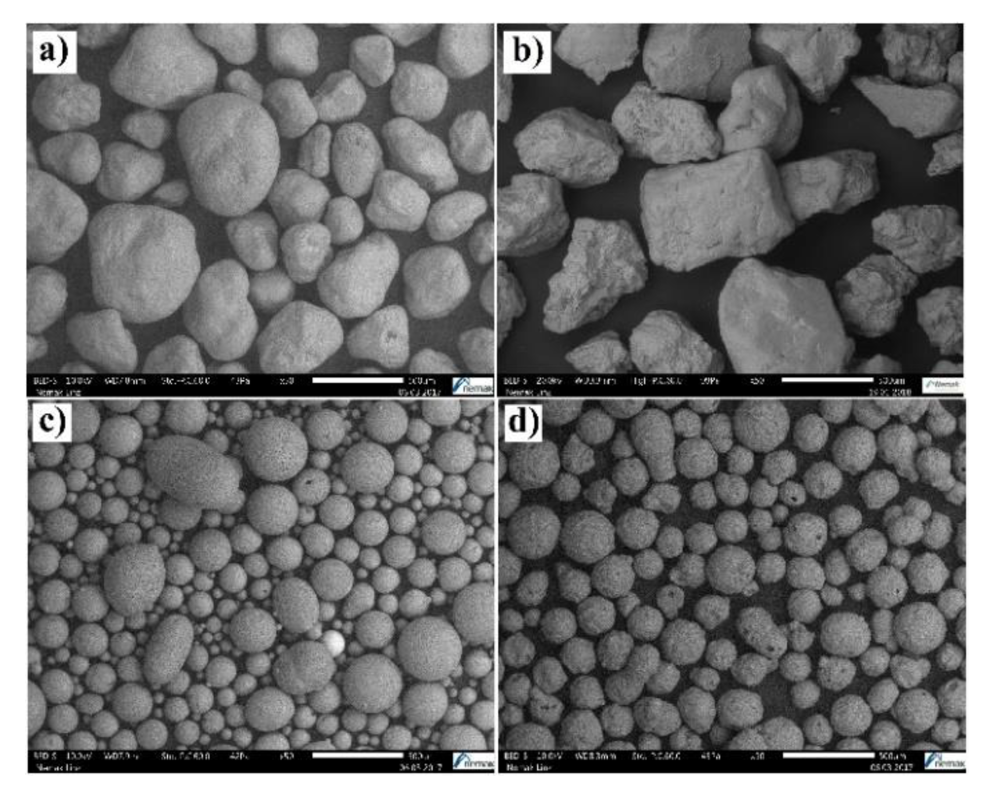
| A Coarse | Slovakia | Silica (97.6% SiO2) | Al2O3 (1.3%), K2O + Na2O (0.9%) | rounded | 40 |
| A Fine | Slovakia | Silica (96.3% SiO2) | Al2O3 (2%), K2O + Na2O (1.4%) | rounded | 70 |
| B | Czech | Silica (99.2% SiO2) | K2O + Na2O (0.1%) | angular | 65 |
| C | Asia | Synthetic bauxite (>85% Al2O3, <10% SiO2) | Fe2O3 (<3%) | spherical | 65 |
| D | Asia | Synthetic mullite (61% Al2O3, 36% SiO2) | not specified | spherical | 65 |
| A Coarse [%] | A Fine [%] | Sth [cm2.g−1] | AFS GFN | MKcalc [mm] | Fines Content < 0.125 mm [%] |
|---|---|---|---|---|---|
| 100 | 0 | 61.45 | 42.8 | 0.387 | 0.286 |
| 90 | 10 | 67.70 | 46.1 | 0.364 | 0.281 |
| 80 | 20 | 71.91 | 46.5 | 0.354 | 0.527 |
| 70 | 30 | 77.72 | 48.3 | 0.332 | 0.770 |
| 60 | 40 | 83.24 | 51.1 | 0.314 | 0.729 |
| 50 | 50 | 93.52 | 56.6 | 0.283 | 1.850 |
| 40 | 60 | 96.61 | 60.3 | 0.270 | 1.507 |
| 30 | 70 | 100.57 | 63.3 | 0.256 | 1.507 |
| 20 | 80 | 104.01 | 65.4 | 0.244 | 1.709 |
| 10 | 90 | 110.72 | 68.5 | 0.221 | 2.118 |
| 0 | 100 | 118.24 | 72.6 | 0.201 | 2.368 |
| A Coarse [%] | Sand B [%] | Sth [cm2.g−1] | AFS GFN | MKcalc [mm] | Fines Content < 0.125 mm [%] |
|---|---|---|---|---|---|
| 100 | 0 | 61.45 | 42.8 | 0.387 | 0.286 |
| 90 | 10 | 65.29 | 43.7 | 0.374 | 0.446 |
| 80 | 20 | 71.56 | 46.4 | 0.353 | 0.792 |
| 70 | 30 | 75.67 | 47.7 | 0.339 | 0.999 |
| 60 | 40 | 79.33 | 49.4 | 0.326 | 1.134 |
| 50 | 50 | 87.00 | 51.6 | 0.308 | 2.273 |
| 40 | 60 | 90.29 | 53.5 | 0.297 | 2.442 |
| 30 | 70 | 95.36 | 56.4 | 0.281 | 2.831 |
| 20 | 80 | 98.23 | 58.8 | 0.271 | 2.691 |
| 10 | 90 | 101.57 | 61.4 | 0.261 | 3.051 |
| 0 | 100 | 109.13 | 66.3 | 0.239 | 4.149 |
| A Coarse [%] | Sand C [%] | Sth [cm2.g−1] | AFS GFN | MKcalc [mm] | Fines Content < 0.125 mm [%] |
|---|---|---|---|---|---|
| 100 | 0 | 61.45 | 42.8 | 0.387 | 0.286 |
| 90 | 10 | 68.04 | 45.0 | 0.363 | 0.883 |
| 80 | 20 | 72.44 | 45.8 | 0.353 | 1.567 |
| 70 | 30 | 78.82 | 48.5 | 0.331 | 2.271 |
| 60 | 40 | 84.33 | 49.7 | 0.319 | 3.496 |
| 50 | 50 | 89.32 | 52.7 | 0.297 | 3.270 |
| 40 | 60 | 93.91 | 54.6 | 0.284 | 4.012 |
| 30 | 70 | 99.76 | 57.4 | 0.267 | 4.904 |
| 20 | 80 | 101.67 | 59.2 | 0.256 | 4.496 |
| 10 | 90 | 107.14 | 62.4 | 0.240 | 5.337 |
| 0 | 100 | 115.09 | 67.6 | 0.220 | 6.889 |
| A Coarse [%] | Sand D [%] | Sth [cm2.g−1] | AFS GFN | MKcalc [mm] | Fines Content < 0.125 mm [%] |
|---|---|---|---|---|---|
| 100 | 0 | 61.45 | 42.8 | 0.387 | 0.286 |
| 90 | 10 | 66.61 | 43.9 | 0.367 | 0.415 |
| 80 | 20 | 71.11 | 45.5 | 0.351 | 0.375 |
| 70 | 30 | 75.80 | 47.8 | 0.334 | 0.372 |
| 60 | 40 | 81.20 | 50.4 | 0.315 | 0.448 |
| 50 | 50 | 86.83 | 53.5 | 0.298 | 0.725 |
| 40 | 60 | 92.15 | 58.2 | 0.280 | 0.689 |
| 30 | 70 | 96.92 | 61.5 | 0.262 | 0.745 |
| 20 | 80 | 101.49 | 64.2 | 0.247 | 0.758 |
| 10 | 90 | 106.83 | 66.9 | 0.229 | 0.907 |
| 0 | 100 | 112.29 | 69.4 | 0.211 | 1.055 |
© 2020 by the authors. Licensee MDPI, Basel, Switzerland. This article is an open access article distributed under the terms and conditions of the Creative Commons Attribution (CC BY) license (http://creativecommons.org/licenses/by/4.0/).
Share and Cite
Vasková, I.; Varga, L.; Prass, I.; Dargai, V.; Conev, M.; Hrubovčáková, M.; Bartošová, M.; Buľko, B.; Demeter, P. Examination of Behavior from Selected Foundry Sands with Alkali Silicate-Based Inorganic Binders. Metals 2020, 10, 235. https://doi.org/10.3390/met10020235
Vasková I, Varga L, Prass I, Dargai V, Conev M, Hrubovčáková M, Bartošová M, Buľko B, Demeter P. Examination of Behavior from Selected Foundry Sands with Alkali Silicate-Based Inorganic Binders. Metals. 2020; 10(2):235. https://doi.org/10.3390/met10020235
Chicago/Turabian StyleVasková, Iveta, László Varga, Ingo Prass, Viktoria Dargai, Martin Conev, Martina Hrubovčáková, Marianna Bartošová, Branislav Buľko, and Peter Demeter. 2020. "Examination of Behavior from Selected Foundry Sands with Alkali Silicate-Based Inorganic Binders" Metals 10, no. 2: 235. https://doi.org/10.3390/met10020235
APA StyleVasková, I., Varga, L., Prass, I., Dargai, V., Conev, M., Hrubovčáková, M., Bartošová, M., Buľko, B., & Demeter, P. (2020). Examination of Behavior from Selected Foundry Sands with Alkali Silicate-Based Inorganic Binders. Metals, 10(2), 235. https://doi.org/10.3390/met10020235