Abstract
The final mechanical properties of hot-stamped steel are determined by the microstructures which are greatly influenced by the cooling process after hot stamping. This research studied the effect of the cooling path on the microstructures and hardness of 22MnB5 hot-stamped steel. The cooling path was divided into continuous and discontinuous (primary and secondary) processes. After cooling, the Vickers hardness along the thickness of the specimens was measured. The results indicate that, for a continuous cooling process, there was a critical cooling rate of 25 °C/s to obtain fully martensitic microstructure. For the discontinuous cooling process, the slower was the cooling rate, the higher was the degree of auto-tempering that occurred, and the greater was the amount of carbides that formed, regardless of the primary or secondary cooling rate. When the cooling rate was lower than the critical value, a higher primary cooling rate suppressed the auto-tempering of lath martensite and increased the quenched hardness. By contrast, the hardness was not sensitive to the cooling rate when it exceeded the critical value.
1. Introduction
Due to the increasing demand for vehicle weight reduction, safety improvement, and improved crashworthiness, ultra-high strength steels have become more and more popular to manufacture automobile structural components [1]. The application of ultra-high strength steels inevitably brings about the problems of springback [2], mold wear, etc. Hot stamping is a promising process that can deal with these problems [3,4,5]. The hot-stamped steel is usually heated to an austenitizing temperature of 900–950 to obtain low strength and high formability [4]. The steel sheet is then press formed and simultaneously quenched hardened with the die to obtain an intended shape and high strength due to a fully martensitic microstructure. The hot-stamped steel is widely used in manufacturing of automobile components, such as body pillars, rockers, roof rails, bumpers, and door intrusion beams [6]. The hot-stamped 22MnB5 steel is one of the most commonly used steel grades in hot stamping processes. It has a given microstructure consisting of ferrite and pearlite with a tensile strength of about 600 MPa. After the hot stamping process, the component finally has a martensitic microstructure with a total strength of about 1500 MPa and elongation of no less than 5%.
The ultra-high strength of hot-stamped steel is attributed to its fully martensitic microstructure. According to previous research, the final mechanical properties and microstructures of hot-stamped steel were greatly influenced by cooling conditions [7,8,9]. For a continuous cooling process, there is a critical cooling rate to obtain a fully martensitic microstructure [4,10,11]. However, in the industrial hot stamping process, the steel sheet is cooled at varying cooling rates [9], decreasing from the value more than 60 to less than 10 . A slow cooling rate below martensite start () temperature facilitates the formation of carbides, causing auto-tempering [12], reducing quenched hardness [13] and strength [14]. Martensite features high strength and high-density dislocations [15]. Auto-tempering of martensite usually occurs immediately when martensite forms [16]. The tempering of martensite is accompanied by the formation of carbides [16,17,18,19,20,21], which consumes the carbon of the martensite matrix, leading to a decrease in effective carbon content [22] and dislocation density [23,24]. A lot of research has been conducted on the phase transformation of hot-stamped steels as well as the tempering of martensite under isothermal conditions. Few attempts have been made to explore the auto-tempering and phase transformation of hot-stamped steel in discontinuous cooling process. In this research, we studied the effect of cooling path on the microstructures and hardness of hot-stamped 22MnB5 steel.
2. Materials and Experimental Procedure
The hot-stamped 22MnB5 steel was used in this study with the chemical composition shown in Table 1. Specimens with dimensions of 1.8 mm × 4 mm × 10 mm were machined from the hot-rolled strip produced by Compact Strip Production (CSP) process with 1.8 mm in thickness. The thermal dilatation of specimens was measured using a dilatometer (DIL 805A) with an induction heating system to investigate the continuous and discontinuous cooling transformation. In this experiment, specimens were heated to 1150 at a heating rate of 10 , holding for 5 min to homogenize the austenite and chemical compositions. Then the austenitized specimens were quenched at a cooling rate of 10 to 950 , holding for 5 s. Afterward, the specimens were divided into two groups with different heat treatments. Specimens in one group were cooled to room temperature with different cooling rates varying from 0.5 to 50 , as shown in Figure 1a. Specimens in the other group were first cooled to 410 (about 12 above temperature) at 25 and 50 , respectively, and then quenched to room temperature with cooling rates ranging from 1 to 50 , as shown in Figure 1b.

Table 1.
Chemical Composition of 22MnB5 Hot-Stamped Steel (wt.%).
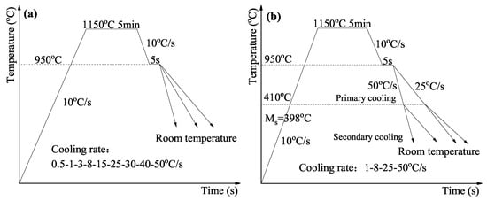
Figure 1.
Schematic diagram of the experimental procedures: (a) continuous cooling process, (b) discontinuous cooling process.
All specimens were ground, polished, and etched using a 4% nitric acid alcohol solution to reveal the microstructure. Axiplan 2 Imaging Zeiss Light Optical Microscope (OM) and Scanning Electron Microscopy (SEM) were used to observe and analyze the microstructures at room temperature. The Vickers hardness was measured by applying 1 kg loading for 5 s along the thickness of the specimens. Standard discs of 3 mm in diameter were prepared by punching the thin foil samples of 60 m in thickness. Then, the thin foils were electropolished in a mixed solution of 5% perchloric acid and 95% alcohol at about 30 by a DJ2000 twin-jet electropolisher. A JEOL JEM-2100F Transmission Electron Microscopy (TEM) was employed to observe the fine lath martensitic structure and carbides of specimens at 200 KV.
3. Results and Discussion
3.1. Continuous Cooling Transformation Behavior
3.1.1. Microstructure and Hardness
The optical and scanning electron micrographs with different cooling rates are represented in Figure 2 and Figure 3. Microstructures consisted of polygonal ferrite and pearlite were formed at a cooling rate of 0.5 , as shown in Figure 2a and Figure 3a. As the cooling rate increased to 1 , less ferrite and pearlite were found, and bainite was observed (Figure 2b and Figure 3b). When the cooling rate increased to 3 , a large volume of granular bainite appeared, and most of the ferrite was needle-like or flake-like, as shown in Figure 2c and Figure 3c. The ferrite disappeared when the sample cooled at a cooling rate of 8 , and the microstructure mainly consisted of granular bainite and lath bainite, as shown in Figure 2d and Figure 3d. The lath bainite was predominant when the cooling rate increased to 15 . It was speculated that martensite may exist at the same time. To obtain a fully martensitic structure, the cooling rate should be greater than 25 , as shown in Figure 2f–i and Figure 3f–i. The results were in good agreement with the previous study [6,10].
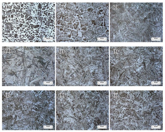
Figure 2.
Microstructures with different continuous cooling process by optical microscopy: (a) 0.5 ; (b) 1 ; (c) 3 ; (d) 8 ; (e) 15 ; (f) 25 ; (g) 30 ; (h) 40 ; and (i) 50 .
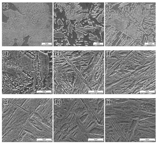
Figure 3.
Microstructures with different continuous cooling process by sanning electron microscopy: (a) 0.5 ; (b) 1 ; (c) 3 ; (d) 8 ; (e) 15 ; (f) 25 ; (g) 30 ; (h) 40 ; and (i) 50 .
To further confirm the types of phases of the samples with different cooling rates, Vickers hardness test was conducted. The result is shown in Figure 4. It could be seen that the hardness value increased from 200 to 456 HV when the cooling rate increased from 0.5 to 25 . Above 25 , the hardness tended to be stable. According to the previous research [25,26,27,28,29], a hardness value between 200 and 250 HV is related to the ferrite phase, while a value greater than 400 HV is attributed to the martensite phase. The decrease in the volume of ferrite and pearlite and the presence of bainite corresponded to the hardness value ranging from 250 to 400 HV. It should be noted that the hardness value of the sample at the cooling rate of 15 was lower than that of samples with higher cooling rate, and presented considerable fluctuations, although the hardness value was greater than 400 HV. Based on this result, we inferred that this sample was not composed of a fully martensitic structure. We speculated that bainite and martensite coexisted.
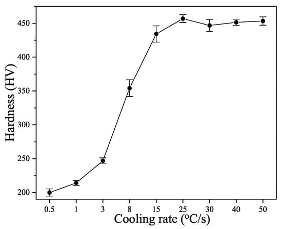
Figure 4.
Vickers hardness of the samples with different continuous cooling rates.
3.1.2. Start and Finish of Phase Transformation
Phase transformation correlates with a change in the crystal structure [16]. In the case of austenite decomposition, volume expansion will occur macroscopically. The dilatometric curves of the samples at different cooling rates were obtained by conducting dilatometric experiment [30]. By tangent method, combining the metallographic and hardness test results, the start and finish temperatures of phase transformation in hot-stamped 22MnB5 steel under different cooling conditions were determined, as shown in Table 2. It should be noted that the start temperature of the sample with a cooling rate of 15 was about 107 higher than the martensite start temperature ( = 396 ). Hence, we could safely confirm that it was not fast enough to eliminate the bainite-like microstructures with a cooling rate of 15 . A cooling rate of 25 is recommended to obtain a fully martensitic microstructure.

Table 2.
Start and Finish Transformation Temperatures of the Steel at Different Cooling Rate.
According to the start and finish temperatures of phase transformation, metallographic and hardness test results with different cooling rates, the continuous cooling transformation (CCT) diagram of hot-stamped 22MnB5 steel was obtained, as shown in Figure 5. It can be seen that 25 is a critical cooling rate, and only when this value is exceeded can a fully martensite structure be obtained.
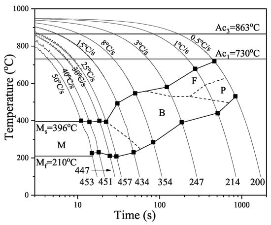
Figure 5.
The CCT diagram of hot-stamped 22MnB5 steel.
3.2. Discontinuous Cooling Process
3.2.1. Microstructures
Effect of secondary cooling rate with the primary cooling rate of 25 .
Based on previous research [6,10,11] and aforementioned experimental results, the cooling rate must be greater than 25 to obtain a fully martensitic microstructure, otherwise diffusion phase transformations would occur. The martensite start temperature was tested ay about 396 by dilatometry. To ensure that there was no martensite transformation at the beginning of the secondary cooling stage, as well as the temperature uniformity, the temperature at which the secondary cooling started was set to 410 , about 14 higher than the temperature.
The scanning electron micrographs of specimens with different cooling rates after cooled to 410 at 25 are displayed in Figure 6. It can be seen that the higher cooling rates facilitated the formation of lath martensite at room temperature, as shown in Figure 6a,b. The lath width seemed to be smaller as the cooling rate increased. When the cooling rate decreased, well auto-tempered martensite appeared [13]. The martensitic lath boundaries became blurred and the lath structure coarsened. Carbides preferentially precipitated at the grain or lath boundaries [31], demonstrating the elongated packet-lath morphology of lath before auto-tempered [32], as shown in Figure 6c. As the secondary cooling rate decreased to 1 , the lath martensite structure was well-tempered. In some region, the carbide coarsened and recrystallization of ferrite occurred [33].
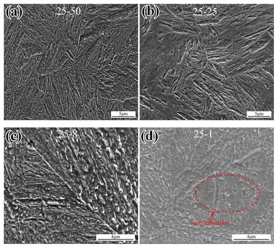
Figure 6.
Microstructures with the primary cooling rate of 25 at different secondary cooling rates of: (a) 50 ; (b) 25 ; (c) 8 ; and (d) 1 .
Detailed morphologies of lath and intra-lath carbides with the cooling rates of 50 and 25 are presented in Figure 7. It can be seen that the lath width increased as the cooling rate decreased. More large laths could be found in the samples with the cooling rate of 25 . Needle-like intra-lath carbide could be found in both cases resulting from the auto-temping process. It should be noted that the needle-like carbide in the sample at the cooling rate of 50 (Figure 7c) was much finer than that of the sample at the cooling rate of 25 (Figure 7d). The dislocation density of the sample in Figure 7a,c was higher. The carbide in the sample shown in Figure 7b,d seemed to have begun to coarsen.
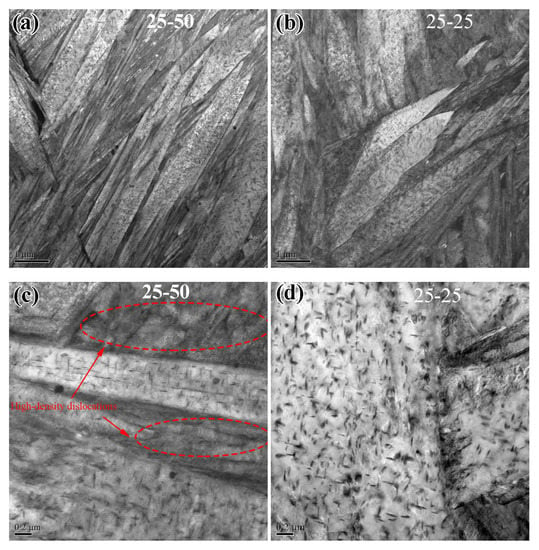
Figure 7.
Detailed morphology of lath and carbides with a primary cooling rate of 25 and the secondary cooling rate of: (a,c) 50 ; and (b,d) 25 .
The formation and ripening of carbides reduce the effective carbon content of the martensite matrix when auto-tempering occurs [22,34]. A martensite grain is hierarchically divided into packet, block, and lath [22,35,36,37]. In lath martensite, there is as high as an order of 10–10 dislocation density [15]. The majority of carbon atoms are trapped in the vicinity of dislocation, forming the Cottrell atmosphere [38,39]. According to previous research [22], when the effective carbon content decreases, the lath and block width increases, and the dislocation density decreases. To obtain a martensitic structure without auto-tempering, the cooling rate should exceed 300 [13]. The cooling rate in this research was not high enough. Therefore, although it was equal or higher than the critical cooling rate to form fully martensitic microstructure, auto-tempering and formation of carbide were inevitable. The lower is the cooling rate, the higher is the strength of auto-tempering, the coarser are the carbides, and the lower is the dislocation density (Figure 7).
Effect of secondary cooling rate with the primary cooling rate of 50 .
The scanning electron micrographs of specimens in different cooling processes after being cooled to 410 at 50 are presented in Figure 8. The microstructure was mainly composed of auto-tempered martensite. Similar to the results in the previous section, with the decrease of cooling rate, the amount and size of carbides increased. The lath boundary was getting blurred, but the lath morphology could still be distinguished.
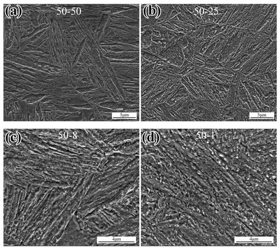
Figure 8.
Microstructures with the primary cooling rate of 50 at different secondary cooling rates of: (a) 50 ; (b) 25 ; (c) 8 ; and (d) 1 .
Figure 9 shows the lath morphology and carbide in detail of the samples with cooling rates of 50 and 25 . There were needle-shaped intra-lath carbides in the relatively wider lath of both samples. The martensite transforms sequentially [40,41]. These wide laths were deduced to be primary martensite which underwent auto-tempering first, making the lath coarsening [32,41,42]. It should be noted that more needle-shaped carbides with four directions were found in the sample with a cooling rate of 25 , as shown in Figure 9d. As for the less-tempered regions, there was no obvious difference in lath width and dislocation density, as shown in Figure 9c,d.
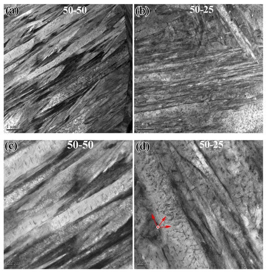
Figure 9.
Detailed morphology of lath and carbides with a primary cooling rate of 50 and the secondary cooling rate of: (a,c) 50 ; and (b,d) 25 .
Effect of primary cooling rate.
Comparing Figure 7 and Figure 9, we can infer that the slower primary cooling rate facilitates the auto-tempering of martensite. The lath width of the sample with primary cooling rate of 25 (Figure 7a,b) was wider than that of the sample with cooling rate of 50 (Figure 9a,b). More intra-lath carbides are found in Figure 7c,d than in Figure 9c,d. Moreover, the carbide in Figure 7d tend to coarsen, whereas they remain needle-shaped in Figure 9d. These subtle detailed differences could not be observed clearly in SEM images (compare Figure 6a,b and Figure 8a,b). As the secondary cooling rate decreased to 8 and 1 (Figure 6c,d and Figure 8c,d), the influence of the primary cooling rate became more obvious. Auto-tempered lath martensite with elongated packet-lath morphology was observed in the samples with the primary cooling rate of 50 , as shown in Figure 8c,d, by contrast, the lath boundaries shown in Figure 6c seemed more blurred, and even the recrystallization of ferrite was found, as shown in Figure 6d.
3.2.2. Hardness
Experimental Vickers hardness of the samples with the different cooling path is given in Figure 10. It can be seen that the hardness increased with the secondary cooling rate, regardless of the primary cooling rate. The hardness value leveled off when the secondary cooling rate was equal to or above 25 , with a stable value of approximately 456 HV. However, as discussed in previous sections, the auto-tempering process was influenced by the cooling rate, not only the secondary but also the primary cooling rate. The precipitated carbides varied in amount and morphology, affected the effective carbon content, and should make a difference in the quenched hardness [43]. This contradiction was inferred to be due to the effect of precipitation hardening of the carbides [44]. On the one hand, the precipitation of carbides reduces the effective carbon content of the matrix, coarsens the lath martensite, and reduces the dislocation density [23,24]. On the other hand, the precipitated carbides play a role in hardening by pinning dislocations. The comprehensive effect was that the hardness was not very sensitive to the cooling rate and path when the cooling rate was higher than the critical value, 25 .
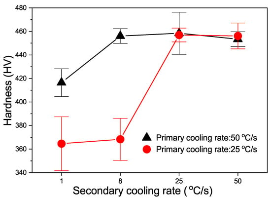
Figure 10.
Vickers hardness of the samples with discontinuous cooling rates.
A great discrepancy in hardness was found between the primary cooling rates of 25 and 50 when the secondary cooling rates decreased to 8 and 1 . This was consistent with the metallographic results, shown in the previous section. A higher primary cooling rate made the lath martensite less tempered, as shown in Figure 8c,d. The hardness value of the sample with cooling rates of 50 (primary) and 8 (secondary) was as high as 456 HV, 88 HV higher than that of the case with the primary cooling rate of 25 . This value was almost identical to those with high cooling rates equal or above 25 , although auto-tempered martensite was found clearly in Figure 8c. The hardness value of the sample with the primary cooling rate of 50 was still higher, even when the secondary cooling rate decreased to as low as 1 .
The tempering of martensite involves five different stages [16,17,18,19,20,21]: redistribution of carbon atoms, the precipitation of - or -carbide, the formation of Hgg carbide, the decomposition of retained austenite, and the formation of cementite and recrystallization of ferrite. As for auto-tempering during a quenching process, the formation of carbides occurs immediately when austenite transforms to martensite. Undoubtedly, the first stage of auto-tempering must be the redistribution of carbon atoms as well [38], forming carbon atom clusters. These carbon atom clusters contribute to the formation of carbides [45,46]. According to the experimental results of this study, the primary cooling rate had a great influence on the martensite auto-tempering process. This fact indicated that the formation of carbon atom clusters due to redistribution had occurred well above the martensite start temperature. These carbon atom clusters played a significant role in carbides formation during auto-tempering of the subsequent cooling process.
4. Conclusions
This research clarified the effect of the cooling path on the hardness and microstructures of hot-stamped boron steel. The following conclusions can be drawn:
- In the continuous cooling process, there is a critical cooling rate of 25 for the formation of a fully martensitic microstructure in hot-stamped 22MnB5 steel.
- The secondary cooling rate greatly affects the auto-tempering of martensite transformed. The amount of carbides decreases with the secondary cooling rate. The hardness increases with secondary cooling rate when the cooling rate is lower than 25 , above which the hardness is not sensitive to the cooling rate.
- The primary cooling rate determines whether a martensite structure is formed. A higher primary cooling rate will inhibit the martensite auto-tempering and reduce and refine carbides. The discrepancy in hardness between the primary cooling rate diminishes when the secondary cooling rate is above 25 .
Author Contributions
Conceptualization, Y.X.; methodology, Y.X.; validation, Y.X., G.Y. and S.B.; formal analysis, Y.X. and Q.J.; investigation, Y.X. and G.Y.; resources, X.M. (Xiaodong Miao); data curation, X.M. (Xiaodong Miao); writing—original draft preparation, Y.X. and Q.J.; writing—review and editing, Y.X. and S.B.; visualization, Y.X. and Q.J.; supervision, G.Z.; project administration, G.Z.; and funding acquisition, X.M. (Xinping Mao). All authors have read and agreed to the published version of the manuscript.
Funding
This research was funded by the Major Projects of Technology Innovation of Hubei Province (2017AAA113), Hubei Natural Science Foundation (2018CFB121).
Conflicts of Interest
The authors declare no conflict of interest.
References
- Venturato, G.; Novella, M.; Bruschi, S.; Ghiotti, A.; Shivpuri, R. Effects of Phase Transformation in Hot Stamping of 22MnB5 High Strength Steel. Procedia Eng. 2017, 183, 316–321. [Google Scholar] [CrossRef]
- Kesvarakul, R.; Chianrabutra, C.; Sirigool, W. Applying 2k Factorial Design to Study on Parameters Affecting Springback of Forming of Advanced High Strength Steel Sheets (AHSS). In Applied Mechanics and Materials; Trans Tech Publications: Stafa-Zurich, Switzerland, 2017; Volume 872, pp. 83–88. [Google Scholar]
- Fan, D.W.; Kim, H.S.; De Cooman, B.C. A Review of the Physical Metallurgy related to the Hot Press Forming of Advanced High Strength Steel. Steel Res. Int. 2009, 80, 241–248. [Google Scholar]
- Karbasian, H.; Tekkaya, A.E. A review on hot stamping. J. Mater. Process. Technol. 2010, 210, 2103–2118. [Google Scholar] [CrossRef]
- Merklein, M.; Lechler, J. Investigation of the thermo-mechanical properties of hot stamping steels. J. Mater. Process. Technol. 2006, 177, 452–455. [Google Scholar] [CrossRef]
- Merklein, M.; Wieland, M.; Lechner, M.; Bruschi, S.; Ghiotti, A. Hot stamping of boron steel sheets with tailored properties: A review. J. Mater. Process. Technol. 2016, 228, 11–24. [Google Scholar] [CrossRef]
- Suh, C.H.; Jang, W.S.; Oh, S.K.; Lee, R.G.; Jung, Y.C.; Kim, Y.S. Effect of cooling rate during hot stamping on low cyclic fatigue of boron steel sheet. Met. Mater. Int. 2012, 18, 559–566. [Google Scholar] [CrossRef]
- Li, X.; Yan, X.; Zhang, Z. Springback Prediction of a Hot Stamping Component Based on the Area Fractions of Phases. Metals 2019, 9, 694. [Google Scholar] [CrossRef]
- Li, F.; Fu, M.; Lin, J. Effect of cooling path on the phase transformation of boron steel 22MnB5 in hot stamping process. Int. J. Adv. Manuf. Technol. 2015, 81, 1391–1402. [Google Scholar] [CrossRef]
- Merklein, M.; Lechler, J.; Geiger, M. Characterisation of the Flow Properties of the Quenchenable Ultra High Strength Steel 22MnB5. CIRP Ann. Manuf. Technol. 2006, 55, 229–232. [Google Scholar] [CrossRef]
- Zhang, P.; Zhu, L.; Xi, C.; Luo, J. Study on Phase Transformation in Hot Stamping Process of USIBOR® 1500 High-Strength Steel. Metals 2019, 9, 1119. [Google Scholar] [CrossRef]
- Chang, Z.Y.; Li, Y.J.; Wu, D. Enhanced ductility and toughness in 2000 MPa grade press hardening steels by auto-tempering. Mater. Sci. Eng. A 2020, 784, 139342. [Google Scholar] [CrossRef]
- Nishibata, T.; Kojima, N. Effect of quenching rate on hardness and microstructure of hot-stamped steel. J. Alloys Compd. 2013, 577, S549–S554. [Google Scholar] [CrossRef]
- Tabata, S.i.; Hikida, K.; Kojima, N.; Mizui, N. Effect of Microstructures on Yield Strength in Hot-Stamped Steel Sheet. In MATEC Web of Conferences; EDP Sciences: Evry, France, 2015; Volume 33. [Google Scholar]
- Morito, S.; Nishikawa, J.; Maki, T. Dislocation Density within Lath Martensite in Fe-C and Fe-Ni Alloys. ISIJ Int. 2003, 43, 1475–1477. [Google Scholar] [CrossRef]
- Bhadeshia, H.; Honeycombe, R. Steels: Microstructure and Properties; Butterworth-Heinemann: Oxford, UK, 2017. [Google Scholar]
- Bhadeshia, H.; Chintha, A.; Lenka, S. Critical Assessment 34: Are χ (Hägg), η and ϵ carbides transition-phases relative to cementite in steels? Mater. Sci. Technol. 2019, 35, 1301–1305. [Google Scholar] [CrossRef]
- Bhadeshia, H.K.D.H. Cementite. Int. Mater. Rev. 2020, 65, 1–27. [Google Scholar] [CrossRef]
- Waterschoot, T.; Verbeken, K. Tempering kinetics of the martensitic phase in DP steel. ISIJ Int. 2006, 46, 138–146. [Google Scholar] [CrossRef]
- Cheng, L.; Brakman, C.M.; Korevaar, B.M.; Mittemeijer, E.J. The tempering of iron- carbon martensite; dilatometric and calorimetric analysis. Metall. Trans. A 1988, 19, 2415–2426. [Google Scholar] [CrossRef]
- Ohmori, Y.; Sugisawa, S. The Precipitation of Carbides during Tempering of High Carbon Martensite. Trans. Jpn. Inst. Met. 1971, 12, 170–178. [Google Scholar] [CrossRef]
- Galindo-Nava, E.I.; Rivera-Díaz-del Castillo, P.E.J. A model for the microstructure behaviour and strength evolution in lath martensite. Acta Mater. 2015, 98, 81–93. [Google Scholar] [CrossRef]
- Shi, Z.M.; Gong, W.; Tomota, Y.; Harjo, S.; Li, J.; Chi, B.; Pu, J. Study of tempering behavior of lath martensite using in situ neutron diffraction. Mater. Charact. 2015, 107, 29–32. [Google Scholar] [CrossRef]
- Krauss, G. Tempering of Lath Martensite in Low and Medium Carbon Steels: Assessment and Challenges. Steel Res. Int. 2017, 88, 1700038. [Google Scholar] [CrossRef]
- López de Lacalle, L.N.; Fernández Valdivielso, A.; Amigo, F.J.; Sastoque, L. Milling with ceramic inserts of austempered ductile iron (ADI): Process conditions and performance. Int. J. Adv. Manuf. Technol. 2020, 110, 899–907. [Google Scholar] [CrossRef] [PubMed]
- Fernández-Valdivielso, A.; López de Lacalle, L.; Fernández-Lucio, P.; González, H. Turning of Austempered Ductile Iron with ceramic tools. Proc. Inst. Mech. Eng. Part B J. Eng. Manuf. 2020, 0954405420957154. [Google Scholar] [CrossRef]
- Fernández-Valdivielso, A.; López de Lacalle, L.; Urbikain, G.; Rodriguez, A. Detecting the key geometrical features and grades of carbide inserts for the turning of nickel-based alloys concerning surface integrity. Proc. Inst. Mech. Eng. Part C J. Mech. Eng. Sci. 2016, 230, 3725–3742. [Google Scholar] [CrossRef]
- Abbasi, M.; Naderi, M.; Saeed-Akbari, A. Isothermal versus non-isothermal hot compression process: A comparative study on phase transformations and structure-property relationships. Mater. Des. 2013, 45, 1–5. [Google Scholar] [CrossRef]
- di Schino, A.; Alleva, L.; Guagnelli, M. Microstructure Evolution during Quenching and Tempering of Martensite in a Medium C Steel. Mater. Sci. Forum 2012, 715–716, 860–865. [Google Scholar] [CrossRef]
- Kop, T.A.; Sietsma, J.; Van Der Zwaag, S. Dilatometric analysis of phase transformations in hypo-eutectoid steels. J. Mater. Sci. 2001, 36, 519–526. [Google Scholar] [CrossRef]
- Ju, Y.; Goodall, A.; Strangwood, M.; Davis, C. Characterisation of precipitation and carbide coarsening in low carbon low alloy Q&T steels during the early stages of tempering. Mater. Sci. Eng. A 2018, 738, 174–189. [Google Scholar]
- Caron, R.; Krauss, G. The tempering of Fe-C lath martensite. Metall. Mater. Trans. B 1972, 3, 2381–2389. [Google Scholar] [CrossRef]
- Saha, D.C.; Biro, E.; Gerlich, A.P.; Zhou, Y. Evolution of Transient Nature Nanoscale Softening during Martensite Tempering. Metall. Mater. Trans. A 2020, 51, 3772–3777. [Google Scholar] [CrossRef]
- Galindo-Nava, E.I.; Rivera-Díaz-del Castillo, P.E.J. Understanding the factors controlling the hardness in martensitic steels. Scr. Mater. 2016, 110, 96–100. [Google Scholar] [CrossRef]
- Morito, S.; Huang, X.; Furuhara, T.; Maki, T.; Hansen, N. The morphology and crystallography of lath martensite in alloy steels. Acta Mater. 2006, 54, 5323–5331. [Google Scholar] [CrossRef]
- Zhang, S.; Morito, S.; Komizo, Y.i. Variant selection of low carbon high alloy steel in an austenite grain during martensite transformation. ISIJ Int. 2012, 52, 510–515. [Google Scholar] [CrossRef]
- Suikkanen, P.P.; Cayron, C.; DeArdo, A.J.; Karjalainen, L.P. Crystallographic Analysis of Martensite in 0.2C-2.0Mn-1.5Si-0.6Cr Steel using EBSD. J. Mater. Sci. Technol. 2011, 27, 920–930. [Google Scholar] [CrossRef]
- Hutchinson, B.; Hagström, J.; Karlsson, O.; Lindell, D.; Tornberg, M.; Lindberg, F.; Thuvander, M. Microstructures and hardness of as-quenched martensites (0.1–0.5% C). Acta Mater. 2011, 59, 5845–5858. [Google Scholar] [CrossRef]
- Sherman, D.H.; Cross, S.M.; Kim, S.; Grandjean, F.; Long, G.J.; Miller, M.K. Characterization of the Carbon and Retained Austenite Distributions in Martensitic Medium Carbon, High Silicon Steel. Metall. Mater. Trans. A 2007, 38, 1698–1711. [Google Scholar] [CrossRef]
- Morsdorf, L.; Jeannin, O.; Barbier, D.; Mitsuhara, M.; Raabe, D.; Tasan, C.C. Multiple mechanisms of lath martensite plasticity. Acta Mater. 2016, 121, 202–214. [Google Scholar] [CrossRef]
- Morsdorf, L.; Tasan, C.C.; Ponge, D.; Raabe, D. 3D structural and atomic-scale analysis of lath martensite: Effect of the transformation sequence. Acta Mater. 2015, 95, 366–377. [Google Scholar] [CrossRef]
- Ramesh Babu, S.; Nyyssönen, T.; Jaskari, M.; Järvenpää, A.; Davis, T.P.; Pallaspuro, S.; Kömi, J.; Porter, D. Observations on the Relationship between Crystal Orientation and the Level of Auto-Tempering in an As-Quenched Martensitic Steel. Metals 2019, 9, 1255. [Google Scholar] [CrossRef]
- Tkalcec, I.; Azcoïtia, C.; Crevoiserat, S.; Mari, D. Tempering effects on a martensitic high carbon steel. Mater. Sci. Eng. A 2004, 387–389, 352–356. [Google Scholar] [CrossRef]
- Deng, X.T.; Fu, T.L.; Wang, Z.D.; Misra, R.D.K.; Wang, G.D. Epsilon carbide precipitation and wear behaviour of low alloy wear resistant steels. Mater. Sci. Technol. 2016, 32, 320–327. [Google Scholar] [CrossRef]
- Nagakura, S.; Hirotsu, Y.; Kusunoki, M.; Suzuki, T.; Nakamura, Y. Crystallographic study of the tempering of martensitic carbon steel by electron microscopy and diffraction. Metall. Trans. A 1983, 14, 1025–1031. [Google Scholar] [CrossRef]
- Speich, G.R.; Leslie, W.C. Tempering of steel. Metall. Trans. 1972, 3, 1043–1054. [Google Scholar] [CrossRef]
Publisher’s Note: MDPI stays neutral with regard to jurisdictional claims in published maps and institutional affiliations. |
© 2020 by the authors. Licensee MDPI, Basel, Switzerland. This article is an open access article distributed under the terms and conditions of the Creative Commons Attribution (CC BY) license (http://creativecommons.org/licenses/by/4.0/).