Abstract
During the casting cooling process or the forging process, austenitic stainless steel will remain at around 800 °C for some time. During this period, precipitate particle behaviors in austenitic stainless steel (containing ferrite) will cause a reduction in ductility, which can lead to material cracking. In this study, the effects of aging at 800 °C on the microstructure, impact toughness and microhardness of Z2CND18-12N austenitic stainless steel were systematically investigated. The precipitation processes of the χ and σ phases were characterized by color metallography and back scattered electron (BSE) signals. The toughness was investigated by the Charpy impact test. After the aging treatment, the χ and σ phases precipitated successively in the ferrite, and as the aging duration increased, the χ-phase dissolved and the σ-phase precipitated along the austenite grain boundaries. These all lead to a decrease in toughness and an increase in microhardness. Finally, the relationship between fracture morphology and aging time is discussed herein, and a crack mechanism is given.
1. Introduction
Stainless steels with dual phase structures of austenite and ferrite, such as cast or welded austenite stainless steels and duplex stainless steels, are extensively used in nuclear power industry due to their high strength, plasticity, toughness and intergranular corrosion resistance [1,2,3]. Moreover, it is well known that the ferrite contents in the austenitic stainless steel welds should be controlled in the range of 3–12 vol.% to prevent hot cracking [4,5]. In pressurized water reactor (PWR) nuclear power stations, the stainless steels used by the important members of the pressure boundary of the main loop all have a dual-phase structure [6,7]. However, when undergoing the casting cooling process or forging process, the cores of large austenitic stainless steel members will remain at 600–900 °C for a period of time. Under these conditions, if ferrite is present in the steel, the σ-phase will precipitate in the ferrite and thus affect the properties of the material [8]. In the actual production process, there have been incidents in which the impact toughness is much lower than the required value. The materials studied in this paper are used in the nuclear power industry. Since the operating temperature of pressurized water reactors does not exceed 350 °C, the above situation was often ignored. It results in the material being scrapped before it is put into service. The study of the precipitation behavior of austenitic stainless steels at high temperatures could guide the industrial production process.
Previous studies on the aging processes of austenitic stainless steels mainly focused on medium and low temperatures. Studies showed that thermal aging was mainly caused by the instability of ferrite phase in stainless steel, including the amplitude-modulation decomposition of ferrite, the precipitation of G-phase and the precipitation reaction at the ferrite/austenite phase boundary, among which the amplitude modulation decomposition and G-phase precipitation were considered as the main thermal aging mechanisms [9,10,11,12,13,14]. Tucker et al. [15] studied the amplitude-modulation decompositions of 2003 and 2205 duplex stainless steel aged at 427 °C, and used the three-dimensional atomic probe technology (APT) to intuitively show the distribution of Cr on a two-dimensional scale. Additionally, the results showed that with the extension of thermal aging time, the evenly distributed Cr gradually differentiated into rich Cr region (α’-phase) and poor Cr region (α-phase). In addition, when Mo element was contained in cast or welded stainless steel, fine and dispersed G-phase particles tended to precipitated in ferrite after long-term thermal aging treatment above 350 °C [16,17]. However, the aging mechanism of austenitic stainless steel at high temperatures is different from that at low temperature. The σ-phase can rapidly precipitate in austenitic stainless steel at high temperatures, which greatly reduces the toughness of the materials [18]. Current studies suggested that σ-phase precipitation was related to the composition, microstructure and heat treatment process of the alloy. The diffusion of Cr and Mo in ferrite directly influenced the formation of σ-phase [19,20,21]. An early work by Barcik [22] suggested that austenitic steels would be susceptible to precipitation of σ-phase if the carbon concentration fell below a certain critical value, and the equivalent chromium content was greater than 18%. Besides, the rate of σ-phase precipitation via ferrite was about 100 times faster than the rate of σ-phase precipitation directly from the austenite. In addition, the ferrite in austenitic stainless steel is the δ-ferrite formed during casting or welding; the addition of elemental N could reduce the content of delta ferrite, thereby reducing the precipitation of phase [23]. Schwind et al. [24] concluded from their simulations that the grain size and shape of austenitic stainless steels will influence the precipitation of the σ-phase, of which the grain size is more important. When Mo element was contained in austenitic stainless steel, the precipitation of σ-phase would be accelerated during aging treatment [25]. Mo promoted the precipitation of χ-phase. The precipitation of χ-phase was earlier than σ-phase, and would eventually transform to σ-phase [26,27,28]. In recent work, Da Fonseca et al. proposed that the grain edges were preferred sites for the nucleation of the σ-phase [29]. Although some studies on the aging behavior of stainless steel have been reported, the relationship between the microstructure and properties of austenitic stainless steel at high temperature still needs further research.
In this work, the microstructure and mechanical properties of austenitic stainless steel Z2CND18-12N were studied after aging at 800 °C. The effects of precipitates at different positions on mechanical properties were summarized. Microhardness and toughness at room temperature were determined by microhardness test and Charpy impact test. The process of precipitation of the σ-phase in the aging process was visualized by color metallography. The microstructure transitions during aging were studied by scanning electron microscopy (SEM), back scattered electron (BSE) signals and transmission electron microscopy (TEM). Finally, some suggestions on the residence time of austenitic stainless steel containing ferrite at 800 °C and the subsequent solution treatment were decided upon.
2. Materials and Methods
The test material is Z2CND18-12N austenitic stainless steel. Z2CND18-12N is the safety end piping material used in RCC-M (French nuclear power standard). The final state of the test material is the solution treatment state at 1050–1150 °C. The required value of chemical composition and the measured value are shown in Table 1.

Table 1.
Chemical composition of the specimen (wt.%).
In order to determine the effect of aging treatment at 800 °C on the impact toughness of the material at room temperature, the impact energy of the specimen was tested by the Charpy V impact test. The size of specimen was 55 mm × 10 mm × 10 mm. Each specimen was measured in three groups and averaged. Microhardness tests were conducted at room temperature using a Vickers hardness tester (MVS-1000D1, Guangzhou YDYQ Precision Instruments Co., LTD., Guangzhou, China). The load of the experiment was 500 gf and dwell time was 10 s. Each datum was the average value of 10 indentations.
The precipitation behavior of σ-phase was observed by means of color metallography. The etchant used for color metallography was an aqueous solution of potassium ferrocyanide and potassium hydroxide (PFPH: potassium ferricyanide 30 g, potassium hydroxide 30 g and pure water 60 mL, Wuhan Xinshen Test Chemical Technology Co. LTD., Wuhan, China). The etching condition was boiling etching. Samples after solution and aging treatment were characterized by scanning electron microscopy (SEM: MIRA3-LMH, TESCAN Brno s.r.o., Czech Republic). SEM-BSE was used to analyze the transformation of phases during the aging process based on the correspondence between atomic number and gray-contrast. The chemical composition of each phase was determined by Energy Dispersive Spectrometer (SEM-EDS: Aztec Energy, Oxford Instruments Nanoanalysis, High Wycombe, UK). The phases were identified by electron backscatter diffraction (EBSD: Aztec HKL standard, Oxford Instruments Nanoanalysis, High Wycombe, UK). The EBSD specimens were mechanically polished with high precision (without being etched). The precipitates were further identified by transmission electron microscopy (TEM: JEM2010-HT, JEOL, Tokyo, Japan). TEM specimens were first thinned to 70 μm by grinding and then further thinned to nano-scale by double-jet electropolishing.
3. Results and Discussion
3.1. Microstructure after Solution Treatment
The microstructure of the sample after solution treatment at 1100 ℃ for 1 h is shown in Figure 1. Figure 1 shows that the matrix structure is equiaxial austenite crystal with a grain size of approximately 100 μm. Figure 2 shows that the ferrite with BCC crystal structure was distributed on the austenite matrix, and the size varied from several microns to dozens of microns. Previous studies confirmed that this ferrite was δ-ferrite formed in the casting or welding process [30]. The SEM-BSE image shows the appearance of ferrite and austenite in the background: the ferrite is darker than austenite (Figure 2b). The chemical compositions of two kinds of microstructures with different gray contrast in Figure 2b measured by EDS are shown in Table 2. The contents of Cr and Mo in the ferrite region were 23.94% and 4.38%, respectively, higher than those of Cr and Mo in the austenite region (18.51% and 2.70%). Additionally, the content of Ni in the ferrite region (6.07%) was much lower than that in the austenite region (10.58%). The difference in chemical composition resulted in different contrasts between the two phases in the SEM-BSE image. The difference in chemical composition could be interpreted as the segregation of ferrite forming elements and austenite forming elements during solidification.

Figure 1.
SEM image of sample after solution treatment.
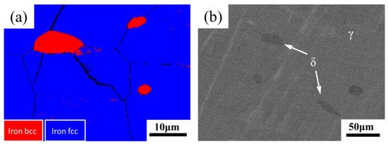
Figure 2.
(a) EBSD image and (b) SEM-BSE image of the sample after solution treatment.
Table 2.
Chemical composition regarding δ-ferrite and austenite measured by EDS (wt.%).
3.2. Microstructure after Aging at 800 °C
The color metallography of samples after aging for different lengths of time is shown in Figure 3. The carbide is dissolved under the condition of etching with aqueous solution of PFPH. Meanwhile σ-phase is light blue or brown, and ferrite is yellow. According to Figure 3, the whole process of ferrite transformation during aging process could be intuitively observed. White austenite and yellow ferrite were found in the sample after solution treatment (Figure 3a). Ferrite was observed to be composed of multiple grains on the sample aged for 2 h (Figure 3b). As aging progressed, it could be found that σ-phase first precipitated at the γ/δ interface or at the grain boundary of δ-ferrite, and then grew into δ-ferrite (Figure 3b–d). When the aging duration increased to 12 h, the ferrite was filled with blue σ-phase (Figure 3e). After this, the phase changed from blue to brown, and ferrite was almost completely transformed into σ-phase (Figure 3f–h).
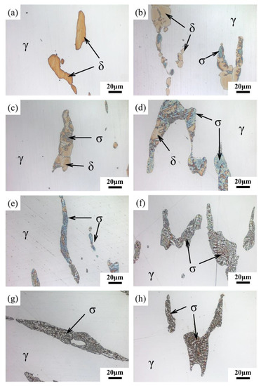
Figure 3.
Color metallography taken with an optical microscope after (a) solution treatment and aging for different lengths of time: (b) 2 h; (c) 4 h; (d) 8 h; (e) 12 h; (f) 24 h; (g) 72 h; (h) 200 h.
Figure 4 shows the BSE images of unetched samples aged at 800 ℃ for different lengths of time. Figure 4a,b shows the same sample aged for 2 h. In Figure 4a, the large ferrite in the middle changes from the dark color in the solution treatment state to the bright color. In addition, the brighter particles could be observed at the γ/δ interface. Meanwhile, some ferrite regions were dark, and unlike the solid solution treatment state, there were brighter particles at the γ/δ interface. When the aging duration ranged from 12 to 24 h, three kinds of gray-contrast were observed in the BSE images of samples (Figure 4c,d). However, after aging for 72 h, the brighter particles at γ/δ interface disappeared, and the bright regions began to extend beyond the ferrite region to the austenite grain boundaries (Figure 4e). In addition, when the aging duration was 200 h, the brighter particles began to appear inside the austenite grains (Figure 4f). EDS analysis was carried out for ferrite region in Figure 4, and the function of the average contents of Cr, Ni and Mo in ferrite region with aging time was measured, as shown in Figure 5. With the increase of aging duration, the contents of Cr and Mo respectively increased by 16c and 83%, and the content of Ni decreased by about 45%. Moreover, the element content changed most dramatically within 12 h after aging.
Figure 4.
SEM-BSE images showing the microstructure evolution of samples aged at 800 °C for: (a) 2 h; (b) 2 h; (c) 12 h; (d) 24 h; (e) 72 h; (f) 200 h.
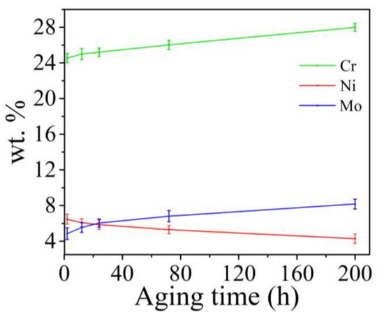
Figure 5.
The function of wt.% of Cr, Ni and Mo with aging time.
According to the changes of contrast and element content in BSE images, the transformation process of microstructure in aging process could be deduced. The BSE image reflects the average atomic number of the observed region [28]. In Figure 4a,b, the ferrite regions with different forms were the three corresponding states during the transformation. At the beginning of the transformation, the Mo element in austenite and ferrite aggregated into the γ/δ interface, and the χ-phase with high content of Mo was precipitated [31], which was the brighter particle in the BSE image. Then σ-phase was precipitated at boundary of χ-phase and γ/δ interface, and grew into ferrite. Finally, σ-phase was full of ferrite region, and the content of Mo reached a high level. The average atomic number of the ferrite region was higher than that of the austenite region, which was shown by the fact that the ferrite region is brighter than the austenite region. When the aging duration ranged from 12 to 24 h, there was no significant change in the SEM-BSE images (Figure 4c,d), which indicated the previous process was still underway. After 72 h aging, the χ-phase at the γ/δ interface was dissolved and transformed into σ-phase [26,27,28]. Moreover, discontinuous σ-phase was precipitated at the austenite grain boundary. When the aging duration increased to 200 h, χ-phase was observed in the austenite grain boundaries and grains. The BSE image of the brighter particles at the grain boundary and the chemical composition at the arrow point measured by EDS are shown in Figure 6. At the same aging time, the Mo content of particles was higher than the average Mo content in ferrite, which again proved that the brighter particles were χ-phase with higher Mo content.
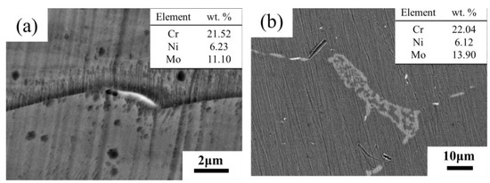
Figure 6.
SEM-BSE image of sample and EDS results at the point of the arrow after aging at 800 °C for (a) 72 h, (b) 200 h.
In order to further identify the precipitates during aging treatment, TEM microstructure and selected area electron diffraction (SAED) patterns were analyzed for samples after aging for 200 h. In bright-field TEM images of the sample aged for 200 h, it was observed that there were coarse particles (Figure 7a). SAED was used to further prove that the coarse particles were σ-phase (Figure 7b). Unfortunately, we were unable to find the diffraction spots for the χ-phase.
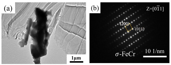
Figure 7.
TEM micrograph of sample aged at 800 °C for different lengths of time: (a) 200 h; (b) electron diffraction pattern of (a).
3.3. Microstructure after Re-Solution Treatment
If the precipitation behavior described above occurs during the cooling process of forging and casting, it can be extremely harmful to industrial production. In order to explore a method to remedy this harmful precipitation, the sample aged at 800 °C for 200 h was re-solution treated at 1100 °C for 1 h. In order to evaluate the transformation of the microstructure after the re-solution treatment, the phase identification mode of EBSD was used to analyze the specimens. Figure 8a showed the presence of δ-ferrite with BCC lattice and γ-phase with FCC lattice in the specimen, and no secondary phase particles were found. SEM-BSE analysis of the re-solution specimens showed that the δ-ferrites became darker again (Figure 8b). In addition, as compared to the aged specimens, the EDS results showed that the contents of Cr and Mo decreased and Ni increased. Comparison of the results after re-solution with those before the aging treatment (Figure 2b) showed that the microstructure and chemical composition of the re-solution treated sample were restored to what they were before the aging treatment. The χ-phase and σ-phases were completely dissolved and transformed into δ-ferrite during the re-solution treatment process. There was full homogenization of the alloying elements in ferrite after re-solution treatment. Moreover, it could be revealed that δ-ferrite was not eliminated by solid solution treatment.
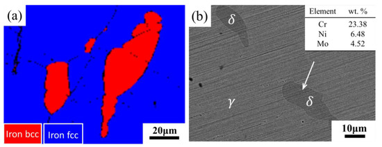
Figure 8.
(a) EBSD image and (b) SEM-BSE image of sample aged for 200 h after solution treatment at 1100 °C for 1 h.
3.4. Impact Property and Microhardness after Aging at 800 °C
It could be seen that the impact energy of the sample decreased with aging time (Figure 9). In particular, the impact energy decreased sharply from 290 to 110 J after 2 h, a decrease of 62.06%. This was because the σ-phase has been precipitated after aging for 2 h, and Figure 4a showed that some ferrites were already full of the σ-phase [26]. When the aging duration increased to 12 h, the σ-phase continued to be precipitated, and the impact energy was 89 J—a decrease by 19.09% compared with 2 h. Due to the overlap of error bars, the impact energy of samples aged 12 and 24 h remained unchanged. The same result could also be obtained from the fact that the microstructures shown in Figure 4c,d do not differ significantly. After aging for 72 h, the impact energy was 53 J, which is a decrease by 36.14% compared with 24 h. This was because the σ-phase began to precipitate at the grain boundary of austenite (Figure 4e), which greatly weakened the grain boundary strength. As the aging duration increased further, the impact toughness of the sample remained almost unchanged. However, it can be seen from Figure 4f that fine χ-phase was precipitated at the austenite grain boundaries and inside the grains. This indicated that fine χ-phase had a little effect on the toughness of the sample compared with the coarse σ-phase.
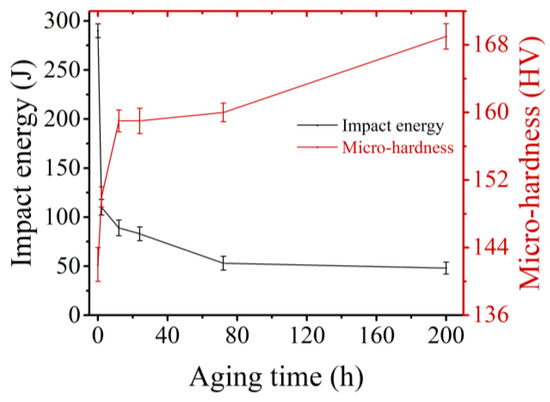
Figure 9.
The function of Charpy impact energy and microhardness of the sample with aging time.
Hardness is not suitable as a measure of σ-phase evolution [32]. However, it could be seen that the trend of micro-hardness with aging time was opposite to that of impact energy with time. This was because the σ-phase, as the fragility phase, reduced the impact energy of the sample, but as the hard phase, it could retard the migration of newly formed dislocations under indentation force. When the aging duration was before 12 h, micro-hardness increased with aging time from 142 to 159 HV, with an increase of 11.97%. This was due to the precipitation of σ-phase. When the aging duration ranged from 12 to 72 h, the microhardness remained unchanged. After aging for 200 h, the microhardness increased from 160 to 169 HV, increasing by 5.62%. As compared to the trend of the impact energy, in the 24–72 h aging stage, the impact energy decreased but the microhardness remains unchanged. This indicated that the intermittent σ-phase (Figure 4e) precipitated along the grain boundary decreased the toughness, but had little effect on the microhardness. In the aging stage of 72 h to 200 h, the impact work remained unchanged while the microhardness increased. In combination with Figure 4f, it could be understood that the fine χ-phase precipitated at the austenite grain boundary and in the grain would not cause the reduction of toughness. However, the micro-hardness was increased because the fine χ-phase blocked the migration of dislocation caused by indentation force.
3.5. Microstructural Analysis after Fracture
The impact fracture morphology of the sample after aging for 200 h was characterized as brittle fracture, and the fracture could be viewed as lots of small undulating planes (Figure 10). The room temperature impact fractures of specimens after aging for different lengths of time were shown as Figure 11. The impact fracture in the solution treated state exhibited massive deep and large dimples (Figure 11a), which indicated that the material had good toughness. However, after 2 h of aging, brittle fracture features (at the red circle) appeared in the sample, and there were deep and large dimples around the brittle features. When the aging duration ranged from 12 to 200 h, secondary cracks appeared in the brittle fracture regions, and the proportion of the dimples decreased. Compared with the sample aged for 2 h, the dimples became small and shallow (Figure 11c–f). The fracture morphology after re-solution treatment was similar to that before the aging treatment, which proved that the toughness of the specimens recovered completely after the re-solution treatment. In addition, it was not difficult to find that the shape and size of all the brittle regions were similar to those of the ferrite in Figure 4. Therefore, it could be inferred that the regions of brittle features were ferrite regions. To further verify this view, EDS analysis was performed on the fracture with aging for 24 h. As shown in Figure 12, the element content of the brittle fracture regions conformed to that of the ferrite regions, and the element composition of the ductile fracture regions conformed to that of the austenite regions.
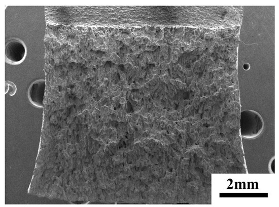
Figure 10.
Macro-fracture of sample after aging at 800 °C for 200 h.

Figure 11.
(a) SEM images of fracture after solution treatment; SEM images of fracture after aging for (b) 2 h; (c) 12 h; (d) 24 h; (e) 72 h; (f) 200 h; and (g) SEM images of fracture after re-solution treatment.
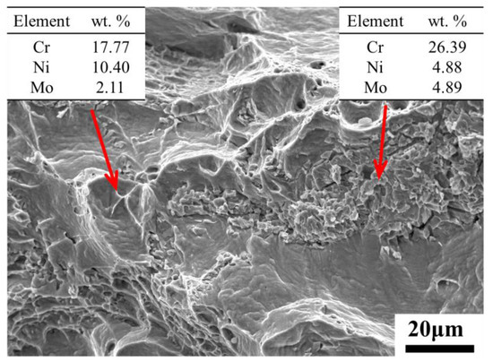
Figure 12.
EDS results of brittle and ductile fracture regions.
In order to clarify the effect of precipitation on toughness during aging process more visually, a schematic illustration of microscopic crack initiation and propagation was given in Figure 13. Since the δ-ferrite transformed into hard and brittle σ-phases after aging, these brittle phases provided conditions for crack initiation. Under the action of tensile stress, cracks first formed in the σ-phase of different ferrite regions and propagated along the σ-phase. The same composition of the brittle regions and the δ-ferrite regions in Figure 12 could be a strong proof. When the crack ran through the entire ferrite region, the crack could not continue to propagate forward along its original course because the austenite region still retained good ductility. Therefore, it eventually tore through the remaining joints in a plastic manner. The initial δ-ferritic regions where the cracks initiation and propagation occurred became small planes, and the final plastic tear was shown as tear ridges and dimples. It was the combination of the ductile austenite and the brittle precipitation phase that made the final result was the small, undulating planes in Figure 10 and the fracture where brittleness and plasticity coexist in Figure 11.
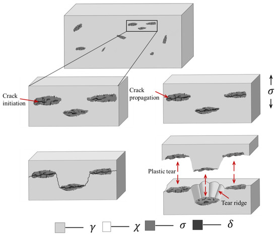
Figure 13.
Schematic illustration of microscopic crack initiation and propagation process of sample after aging.
4. Conclusions
In this paper, the effects of aging at 800 °C for different lengths of time on the microstructure and mechanical properties of Z2CND18-12N austenitic stainless steel were investigated. Based on the results, the following conclusions could be drawn:
- The toughness of the specimens decreased with the increase of aging time. The impact energy dropped sharply at the first 2 h of aging. Subsequently, the declining trend of the impact work became slower, and the impact work did not decline after 72 h, with the lowest value being 53 J. The impact energy decreased by 81.72% compared with the solution treatment state. The trend of microhardness with aging time was opposite to that of impact work.
- The analysis of color metallography and BSE images showed that χ-phase was the first to precipitate at the γ/δ interface during the aging process. Then, precipitation of σ-phase began and grew into ferrite. Ferrite was full of σ-phase when aging duration was 2 h. After aging for 72 h, χ-phase dissolved, and σ-phase began to precipitate along the austenite grain boundary.
- Combined with fracture and EDS analysis, the cracks initiated in the σ-phase and expanded in the ferrite region, and eventually tore the remaining connections in a ductile manner.
- After re-solution treatment, the microstructure and mechanical properties were restored to how they were before the aging treatment. The transformation that occurred under aging conditions was reversible.
- Once δ-ferrite was formed, it cannot be eliminated by heat treatment. Therefore, it is recommended that stainless steels containing ferrite should minimize the residence time in the high temperature zone. In addition, the solution treatment should ensure a sufficiently long time and a sufficiently fast cooling rate to ensure complete dissolution of the secondary phase.
Author Contributions
Conceptualization, W.X. and H.Z.; validation, H.Z., Y.L. and X.Z.; investigation, H.Z. and X.Z.; resources, Y.L.; writing—original draft preparation, H.Z.; writing—review and editing, W.X. and H.Z.; visualization, H.Z.; supervision, W.X.; project administration, Y.L. All authors have read and agreed to the published version of the manuscript.
Funding
This research received no external funding.
Conflicts of Interest
The authors declare no conflict of interest.
References
- da Fonseca, G.S.; Barbosa, L.O.R.; Ferreira, E.A.; Xavier, C.R.; de Castro, J.A. Microstructural, Mechanical, and Electrochemical Analysis of Duplex and Superduplex Stainless Steels Welded with the Autogenous TIG Process Using Different Heat Input. Metals 2017, 7, 538. [Google Scholar] [CrossRef]
- Mathew, M.; Lietzan, L.; Murty, K.; Shah, V. Low temperature aging embrittlement of CF-8 stainless steel. Mater. Sci. Eng. A 1999, 269, 186–196. [Google Scholar] [CrossRef]
- Yi, Y.; Shoji, T. Detection and evaluation of material degradation of thermally aged duplex stainless steels: Electrochemical polarization test and AFM surface analysis. J. Nucl. Mater. 1996, 231, 20–28. [Google Scholar] [CrossRef]
- Lothongkum, G.; Viyanit, E.; Bhandhubanyong, P. Study on the effects of pulsed TIG welding parameters on delta-ferrite content, shape factor and bead quality in orbital welding of AISI 316L stainless steel plate. J. Mater. Process. Technol. 2001, 110, 233–238. [Google Scholar] [CrossRef]
- Olson, D.L. Prediction of austenitic weld metal microstructure and properties. Weld. J. 1985, 64, 281–295. [Google Scholar]
- Ming, H.; Zhang, Z.; Wang, J.; Han, E.-H.; Ke, W. Microstructural characterization of an SA508–309L/308L–316L domestic dissimilar metal welded safe-end joint. Mater. Charact. 2014, 97, 101–115. [Google Scholar] [CrossRef]
- Hale, G.E.; Garwood, S.J. Effect of aging on fracture behaviour of cast stainless steel and weldments. Mater. Sci. Technol. 2013, 6, 230–236. [Google Scholar]
- Chung, H. Aging and life prediction of cast duplex stainless steel components. Int. J. Press. Vessel. Pip. 1992, 50, 179–213. [Google Scholar] [CrossRef]
- Li, S.; Wang, Y.; Zhang, H.; Zheng, K.; Xue, F.; Wang, X. Microstructure evolution and impact fracture behaviors of Z3CN20-09M stainless steels after long-term thermal aging. J. Nucl. Mater. 2013, 433, 41–49. [Google Scholar] [CrossRef]
- Cicero, S.; Setién, J.; Gorrochategui, I. Assessment of thermal aging embrittlement in a cast stainless steel valve and its effect on the structural integrity. Nucl. Eng. Des. 2009, 239, 16–22. [Google Scholar] [CrossRef]
- Li, S.; Wang, Y.; Li, S.; Zhang, H.; Xue, F.; Wang, X. Microstructures and mechanical properties of cast austenite stainless steels after long-term thermal aging at low temperature. Mater. Des. 2013, 50, 886–892. [Google Scholar] [CrossRef]
- Auger, P.; Danoix, F.; Menand, A.; Bonnet, J.; Guttmann, M. Atom probe and transmission electron microscopy study of aging of cast duplex stainless steels. Mater. Sci. Technol. 2013, 6, 301–313. [Google Scholar] [CrossRef]
- Takeuchi, T.; Kakubo, Y.; Matsukawa, Y.; Nozawa, Y.; Toyama, T.; Nagai, Y.; Nishiyama, Y.; Katsuyama, J.; Yamaguchi, Y.; Onizawa, K.; et al. Effects of thermal aging on microstructure and hardness of stainless-steel weld-overlay claddings of nuclear reactor pressure vessels. J. Nucl. Mater. 2014, 452, 235–240. [Google Scholar] [CrossRef]
- Takeuchi, T.; Kameda, J.; Nagai, Y.; Toyama, T.; Matsukawa, Y.; Nishiyama, Y.; Onizawa, K. Microstructural changes of a thermally aged stainless steel submerged arc weld overlay cladding of nuclear reactor pressure vessels. J. Nucl. Mater. 2012, 425, 60–64. [Google Scholar] [CrossRef]
- Tucker, J.D.; Miller, M.; Young, G. Assessment of thermal embrittlement in duplex stainless steels 2003 and 2205 for nuclear power applications. Acta Mater. 2015, 87, 15–24. [Google Scholar] [CrossRef]
- Zhang, B.; Xue, F.; Li, S.; Wang, X.; Liang, N.; Zhao, Y.; Sha, G. Non-uniform phase separation in ferrite of a duplex stainless steel. Acta Mater. 2017, 140, 388–397. [Google Scholar] [CrossRef]
- Hamaoka, T.; Nomoto, A.; Nishida, K.; Dohi, K.; Soneda, N. Effects of aging temperature on G-phase precipitation and ferrite-phase decomposition in duplex stainless steel. Philos. Mag. 2012, 92, 4354–4375. [Google Scholar] [CrossRef]
- Lo, K.H.; Shek, C.; Lai, J. Recent developments in stainless steels. Mater. Sci. Eng. R Rep. 2009, 65, 39–104. [Google Scholar] [CrossRef]
- Sasikala, G.; Ray, S.K.; Mannan, S.L. Kinetics of transformation of delta ferrite during creep in a type 316(N) stainless steel weld metal. Mater. Sci. Eng. A 2003, 359, 86–90. [Google Scholar] [CrossRef]
- Sieurin, H.; Sandström, R. Austenite reformation in the heat-affected zone of duplex stainless steel 2205. Mater. Sci. Eng. A 2006, 418, 250–256. [Google Scholar] [CrossRef]
- Chen, T.; Yang, J. Effects of solution treatment and continuous cooling on σ-phase precipitation in a 2205 duplex stainless steel. Mater. Sci. Eng. A 2001, 311, 28–41. [Google Scholar] [CrossRef]
- Barcik, J. Mechanism of σ-phase precipitation in Cr–Ni austenitic steels. Mater. Sci. Technol. 1988, 4, 5–15. [Google Scholar] [CrossRef]
- Lin, D.-Y.; Liu, G.-L.; Chang, T.-C.; Hsieh, H.-C. Microstructure development in 24Cr–14Ni–2Mn stainless steel after aging under various nitrogen/air ratios. J. Alloy. Compd. 2004, 377, 150–154. [Google Scholar] [CrossRef]
- Schwind, M.; Källqvist, J.; Nilsson, J.-O.; Agren, J.J.; Andren, H. σ-phase precipitation in stabilized austenitic stainless steels. Acta Mater. 2000, 48, 2473–2481. [Google Scholar] [CrossRef]
- Ahn, Y.; Kang, J. Effect of aging treatments on microstructure and impact properties of tungsten substituted 2205 duplex stainless steel. Mater. Sci. Technol. 2000, 16, 382–388. [Google Scholar] [CrossRef]
- Chen, T.; Weng, K.; Yang, J. The effect of high-temperature exposure on the microstructural stability and toughness property in a 2205 duplex stainless steel. Mater. Sci. Eng. A 2002, 338, 259–270. [Google Scholar] [CrossRef]
- Dobranszky, J.; Szabó, P.; Berecz, T.; Hrotko, V.; Portko, M. Energy-dispersive spectroscopy and electron backscatter diffraction analysis of isothermally aged SAF 2507 type superduplex stainless steel. Spectrochim. Acta Part B At. Spectrosc. 2004, 59, 1781–1788. [Google Scholar] [CrossRef]
- Calliari, I.; Zanesco, M.; Ramous, E. Influence of isothermal aging on secondary phases precipitation and toughness of a duplex stainless steel SAF 2205. J. Mater. Sci. 2006, 41, 7643–7649. [Google Scholar] [CrossRef]
- da Fonseca, G.S.; Mendes, P.S.N.; Silva, A.C.M. Sigma Phase: Nucleation and Growth. Metals 2019, 9, 34. [Google Scholar] [CrossRef]
- Padilha, A.F.; Escriba, D.; Materna-Morris, E.; Rieth, M.; Klimenkov, M. Precipitation in AISI 316L(N) during creep tests at 550 and 600 °C up to 10 years. J. Nucl. Mater. 2007, 362, 132–138. [Google Scholar] [CrossRef]
- Michalska, J.; Sozańska, M. Qualitative and quantitative analysis of σ and χ phases in 2205 duplex stainless steel. Mater. Charact. 2006, 56, 355–362. [Google Scholar] [CrossRef]
- Nilsson, J.-O.; Kangas, P.; Wilson, A.J.C.; Karlsson, T. Mechanical properties, microstructural stability and kinetics of σ-phase formation in 29Cr-6Ni-2Mo-0.38N superduplex stainless steel. Met. Mater. Trans. A 2000, 31, 35–45. [Google Scholar] [CrossRef]
Publisher’s Note: MDPI stays neutral with regard to jurisdictional claims in published maps and institutional affiliations. |
© 2020 by the authors. Licensee MDPI, Basel, Switzerland. This article is an open access article distributed under the terms and conditions of the Creative Commons Attribution (CC BY) license (http://creativecommons.org/licenses/by/4.0/).