Article

Selection of Dedicated As-Cast Microstructures in Zn-Al-Cu Alloys for Bearing Applications Supported by Phase-Field Simulations

by
Steffen Gimmler
1,*,
Markus Apel
2 and
Andreas Bührig-Polaczek
1
1
Foundry Institute, RWTH Aachen University, 52072 Aachen, Germany
2
ACCESS e.V., 52072 Aachen, Germany
*
Author to whom correspondence should be addressed.
Metals 2020, 10(12), 1659; https://doi.org/10.3390/met10121659
Submission received: 11 November 2020 / Revised: 7 December 2020 / Accepted: 7 December 2020 / Published: 10 December 2020
(This article belongs to the Special Issue Advances in Metal Casting Technology)

Abstract

:
Solidification and phase formation of Zn-rich Zn-Al-Cu alloys with different Al and Cu contents were investigated. The investigations comprise alloy compositions with either hcp η, fcc α or hcp ε as the primary phase, as well as a composition close to the ternary eutectic point. Test samples were produced in a mold casting process and their microstructures were investigated by scanning electron microscopy. Experimental microstructures are compared with the results from spatially resolved microstructure simulations using a phase-field model. In particular, the dependency between the aluminum and copper contents and the phase fractions of the η, α and ε phases were analyzed. In addition, hardness tests for the samples prove a direct correlation between the α- and ε-phase fractions with the macroscopic hardness of the alloys. A simple model, based on the phase fractions and the properties of the single phases, is suggested for the computation of hardness from the simulation results in order to select appropriate alloy compositions for bearing applications.

1. Introduction

Due to the steady increasing demands for efficiency and economy, the currently used plain bearing materials are increasingly reaching their limits in terms of mechanical and thermal load capacity [1]. In this context, Zn-Al-Cu alloys represent a very promising basis for significantly out-performing conventional white metal alloys in terms of both thermal and mechanical stability, without neglecting the core properties of plain bearings, such as dry sliding properties and adaptability [2]. In general, Zn-Al-alloys show a high compressive strength combined with good tribological properties, such as low friction coefficients and high wear resistance [3,4,5,6]. In order to control the mechanical and tribological properties of these alloys in cast bearing components, knowledge of the microstructure formation along the solidification is essential.
Zn-rich binary Zn-Al alloys are eutectic alloys. In the hypoeutectic range with aluminum contents below 5 wt.%, they solidify primarily in the hexagonal zinc phase η, while in the hypereutectic range, they solidify primarily in the zinc-rich face-centered cubic β phase. Below the eutectic temperature of 382 °C, solidification terminates with a eutectic microstructure composed of η and β phases. When the temperature falls below 275 °C, the β phase becomes unstable and de-composes via a eutectoid reaction into a fine lamellar microstructure of the η phase and the aluminum-rich fcc-α phase [7,8].
Stepping towards a ternary system by the addition of copper yields a ternary eutectic in the Zn-rich corner. Figure 1 depicts an isothermal section and the liquidus projection of the Zn-rich corner, calculated from the CALPHAD data derived from [9]. The isothermal section at 375 °C is slightly below the ternary eutectic point at T = 379 °C (for the composition ZnAl5.43Cu1.68) as can be seen also in the liquidus projection. The four different alloys which have been investigated by phase-field simulations in this paper are marked by filled circles. According to the equilibrium phase diagram, two of these alloys are binary eutectics, and one is located in the single β-phase region. The alloy ZnAl5.5Cu4 (blue dot) is close to the ternary eutectic composition. The addition of a few wt.% copper results not only in a significant increase in strength, presumably due to solid solution hardening, but also in the formation of the intermetallic ε phase when the copper concentration exceeds 2 wt.%. The ε phase of the composition Zn4Cu additionally leads to an increasing strength and hardness as well [5,10,11].
The ε phase is only stable at elevated temperatures, i.e., during and after solidification. Upon further cooling, it tends to react with the surrounding phases through thermally activated de-composition processes via
ε + α → η + T’
where T’ is a stable rhombohedral phase of the composition Al5Zn4Cu [12,13].
However, the transformation of the ε phase can almost be completely bypassed by high cooling rates, so that, depending on the cooling conditions at room temperature, both ε and T’ phases can be present [8,14].
In this paper, the microstructure evolution will be elucidated by a combined approach of casting experiments, thermodynamic equilibrium calculations and thermodynamic coupled phase-field simulations. The major aim is a quantitative correlation between alloy composition and microstructure. Compared to thermodynamic equilibrium calculations, the phase-field method does not only take into account the effect of different cooling rates on phase fractions, but also provides spatially resolved predictions of the microstructure, in particular also for the alloying element distribution, i.e., microsegregation. Thus, phase-field results set the basis for more sophisticated material property models beyond simplified mixture rules. The correlation between “local” hardness and the local Cu concentration suggests that the Cu concentration is the major factor determining the hardness of the alloy.
The combined experimental and computational approach enables tailoring complex three-phase microstructures with a rich variety of even qualitatively different morphologies and therefore a broad spectrum of material properties. The consideration of the solidification kinetic by phase-field simulations is especially important for manufacturing processes showing fast cooling rates, e.g., build-up welding. This will become important when transferring the results from alloy development to production processes for different bearing components.

2. Materials and Methods

2.1. Sample Preparation and Testing Methods

Samples of different compositions were produced by melting pure zinc (Zn 99.995%), pure aluminum (99.8%) and pure copper (99.99%) in an induction furnace and casting the homogenized melt in a cold steel die to reach high cooling rates of about 0.8 °C/s. The overheating was kept constant for all compositions, obtaining comparable casting conditions. Samples were prepared by means of selected grinding and polishing steps with intermediate etching before final polishing to minimize the formation of deformation layers [15].
The microstructures of these samples were examined by scanning electron microscopy (SEM) (Zeiss, Oberkochen, Germany) and energy dispersive X-ray spectroscopy (EDS) (Oxford Instruments, Wiesbaden, Germany) analysis for the morphology and composition of the resulting phases. The Vickers hardness of the individual phases was determined by microhardness measurements (Anton Paar MHT3), whereas Brinell hardness measurements (Karl Frank GmbH, Weinheim, Germany) were carried out to determine the macroscopic hardness of the samples.

2.2. Phase-Field Model

A multiphase-field model was used for spatially and temporally resolved simulations of the microstructure evolution during solidification. In addition to the microstructure, phase-field simulations provide the local element concentration and a quantitative prediction of phase fractions, not only in a 2D slice as in standard metallography, but integrated over a small representative volume of the microstructure. Simulations were performed with the software MICRESS (Version 7.0, ACCESS e.V., Aachen, Germany) [16]. The phase-field model in MICRESS is linked to a thermodynamic CALPHAD database for Al-Cu-Zn [9] and enables quantitative calculations of thermodynamic driving forces and element partitioning between the different phases. The phase-field model and the corresponding evolution equations are described in more detail in a series of papers [17,18,19,20,21]. Further information about the equations is also available in the MICRESS documentation which is freely accessible on the website [16].
Beside the thermodynamic data, further material-related properties as listed in Table 1 were the input data for the simulations. For the diffusion coefficients of Al and Cu in the ternary system Zn-Al-Cu and the interfacial energies, no precise data could be found in the literature; hence, the values applied in the simulations are “educated guesses” with an estimated error of about a factor of 2 for the interfacial energies and a factor of 5 for the diffusion coefficients. The interface mobility was automatically derived from the thin interface limit during the computation to assure diffusion-controlled growth with vanishing kinetic undercooling [21]. Further, an anti-trapping current was added to the diffusion equation to reduce diffuse interface artifacts [21].
The comparison of the simulation results with the experimental micrographs presented in Section 3 shows that the single dataset from Table 1 leads to a reasonable match for all different alloy compositions. However, at this stage, the simulations should be considered as semi-quantitative. A systematic and quantitative comparison between experimental and simulated microstructures offers the opportunity to derive the unknown values with a higher accuracy, which is beyond the scope of this work.
The size of the 3D simulation domain is 100 µm × 50 µm × 100 µm with a uniform grid spacing ∆x = 0.25 µm for all simulations. The phase-field interface thickness is 3 grid cells which is possible by a special finite difference discretization schema [22].
The temperature profiles were calculated via an energy balance equation, balancing an external heat flux given as an input parameter, the release of latent heat and the heat capacity under the assumption of negligible thermal gradients, i.e., the heat conduction is fast enough to maintain a uniform temperature in the simulation domain. By this approach, the cooling curve is a result of the simulation and allows a quantitative comparison with experimental data. A constant heat extraction rate of 65 W/cm3 holds for all simulations shown in this paper. The corresponding solidification time, i.e., the time between Tliquidus and Tsolidius, is around 15 s and close to the experimental values measured for permanent mold castings. The exact value for the solidification time depends on the alloy composition (see, e.g., Figure 2).
The simulations comprise the formation of the three solid phases β-fcc, η-Zn (hcp) and ε-Zn4Cu (hcp) and show the microstructure evolution along the solidification path until the end of solidification. Solid-state transformations at lower temperatures are not considered yet. Nucleation is described by a phenomenological nucleation model [19], which is based on a predefined critical nucleation undercooling ∆Tnuc and a minimal closest distance dmin between neighboring nuclei with ∆Tnuc = 3 K and dmin = 40 µm for all simulations.
An example for the temporal evolution of a solidification microstructure is shown in Figure 2 for the alloy composition Zn20Al0.7Cu. For this alloy, β is the first phase to nucleate. The Al concentration is higher in the solid β phase compared to the melt, thus the Al concentration in the melt decreases during the course of solidification. Eventually, the η-Zn phase nucleates between the β-dendrites. This phase dissolves only a minor amount of Al and appears dark blue in the 3D representation in Figure 2. Depending on the overall eutectic fraction and thus on the alloy composition, η-Zn and β phases partly form a “divorced eutectic” microstructure instead of a lamellar growth structure. Upon further cooling, the primary Zn-rich β phase decomposes into η-Zn and Al-rich α’-fcc Al by a eutectoid reaction which is not part of the current simulation scenario.

2.3. Hardness Computation Model

In order to derive the macroscopic hardness from the simulated microstructures, we propose a correlation between the phase fractions and hardness based on a mixture rule:
HB i = i f i · ( HB 0 i + a i · [ Cu ] i )
where i = β, η or ε, HB 0 i is the hardness of the pure binary phase i without Cu and [Cu]i is the average Cu composition of phase i as derived from the phase-field simulations. The constants ai are a model parameter.

3. Results and Discussions

3.1. Simulated Solidification Path

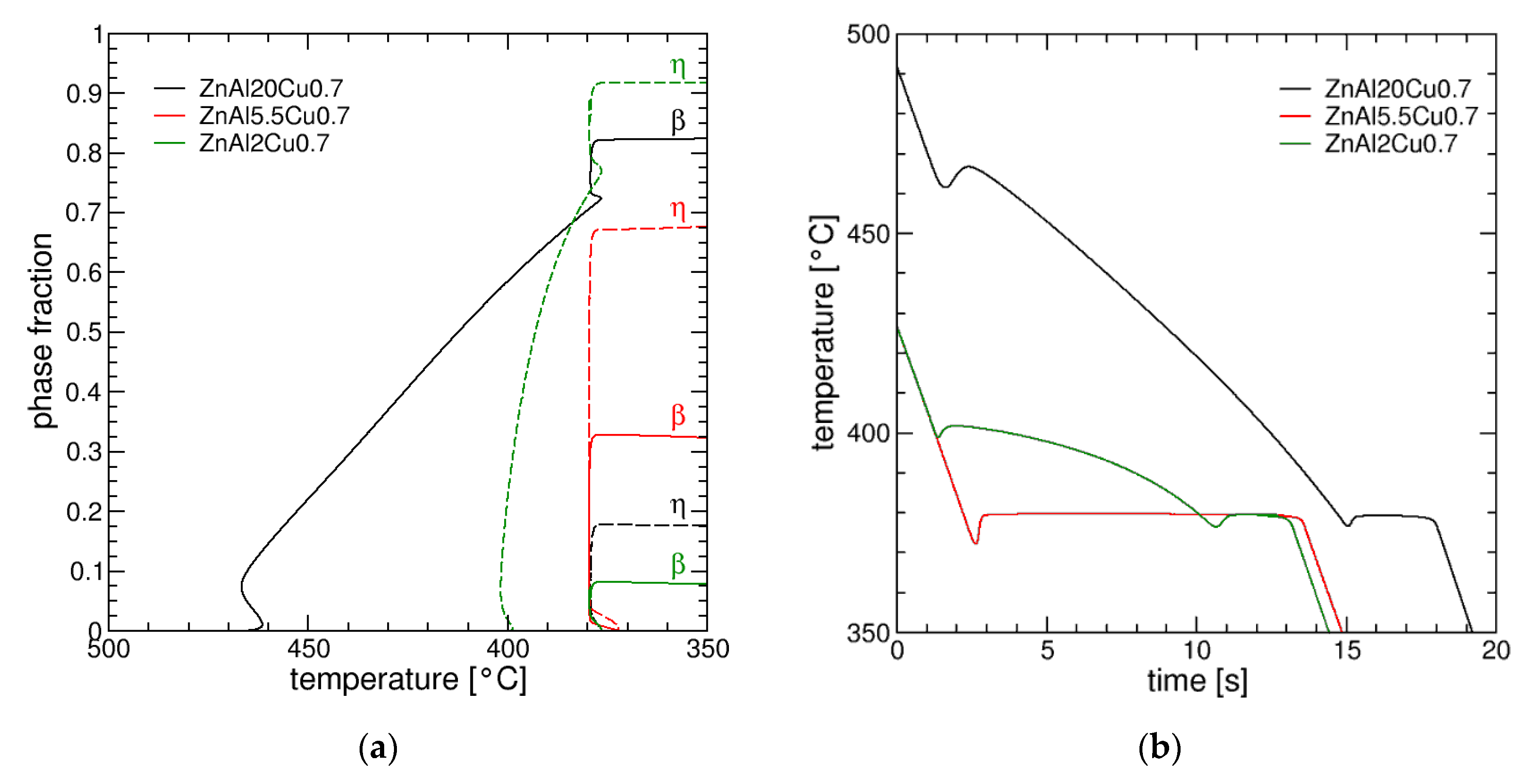
The graph in Figure 3a shows the simulated evolution of the phase fractions as a function of temperature, and the corresponding cooling curves are shown in Figure 3b. The left graph shows that fcc-β is the primary phase in ZnAl20Cu0.7, whereas it is hcp η-Zn in ZnAl2Cu0.7. The eutectic temperature is 379 °C and clearly marked as a steep increase in the phase fractions and a temperature plateau in the cooling curves. Recalescence is visible at the beginning of the primary solidification, but also at the onset of the eutectic reaction. The alloy ZnAl5.5Cu0.7 is close to the eutectic composition and thus characterized by a vanishing solidification interval.
The three alloys demonstrate the rich variety of possible microstructures in this alloy system, as can be seen in the next section.

3.2. Correlation between Alloy Composition and Microstructure

Alloys with different aluminum and constant copper contents were cast in a first step. Like in the simulations, an alloy that solidifies primarily in the zinc-rich η phase (ZnAl2Cu0.7), an alloy close to the ternary eutectic (ZnAl5.5Cu0.7) and an alloy with primary β-phase solidification (ZnAl20Cu0.7) were examined.
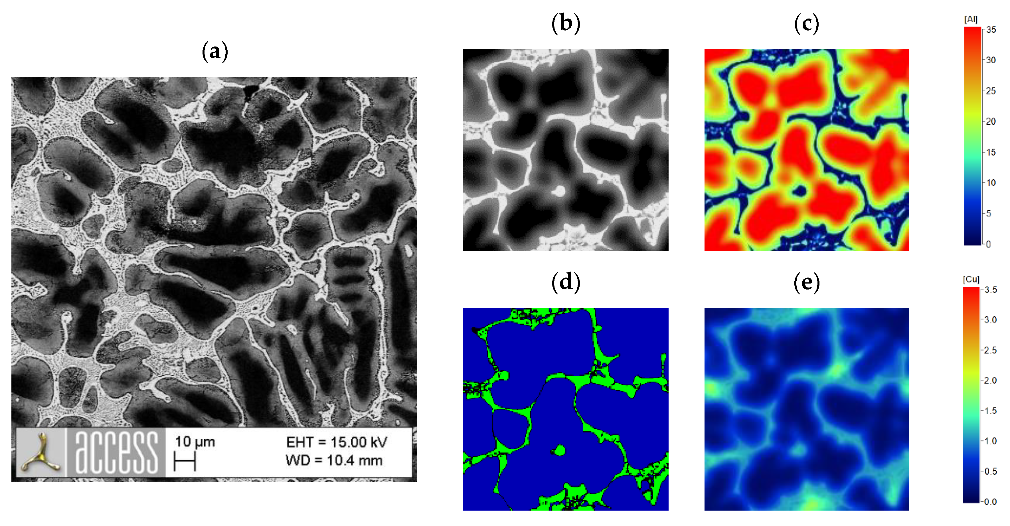
Cooling curves recorded during the casting process give information about the heat extraction rate, which can be used as a process condition for the phase-field simulations. In Figure 4, an SEM image of the microstructure of the alloy ZnAl2Cu0.7, which primarily solidifies in the η phase, is compared with the simulation results.
The comparison shows a good agreement regarding major microstructural features. Primary η-dendrites surrounded by the eutectic are visible with comparable phase fractions and dendrite arm spacings of about 25 µm. The dendritic grain structure is close to globular, i.e., primary trunk and side arms are difficult to distinguish in the 2D section. The phase-field simulation calculates phase fractions of 92% η and 8% β in the as-solidified microstructure. An equilibrium calculation with the same database yields 6.1% β, suggesting that the solidification takes place rather close to equilibrium. The microsegregation pattern for Cu shows that Cu accumulates in areas of the microstructure that solidify last, in particular at the boundaries between eutectic cells. In larger interdendritic areas, the eutectic microstructure is rather lamellar, but due to the geometrical constraint by the primary dendritic network, fibrous or irregular eutectic patterns are present as well.
The eutectic spacing in the simulation is slightly coarser than that found in the experiment. This suggests that either the values of the diffusion coefficients and/or the interfacial energies are too large in the simulations or that there is a difference in the cooling rates between the real casting and simulation. Beside these uncertainties, the grid resolution is another limiting factor: the finest lamella thickness which can be represented by the numerical grid is twice the phase-field interface thickness, i.e., 6 × ∆x = 1.5 µm. This is larger than the experimentally observed spacing. A proper resolution of the eutectic spacing would require a higher grid resolution. Due the increasing computational effort, this would be only feasible on smaller computational domains with volumes below the average grain size. However, the primary target of the phase-field simulations presented in this paper is not to predict the eutectic spacing, but to compute the phase fractions and the Cu microsegregation in the primary phases as input for the hardness calculation. Thus, a more detailed analysis of the eutectic microstructure is a future task which offers the opportunity to derive quantitative values for the solid/liquid interfacial energies and the diffusion coefficients of Al and Cu in the melt.
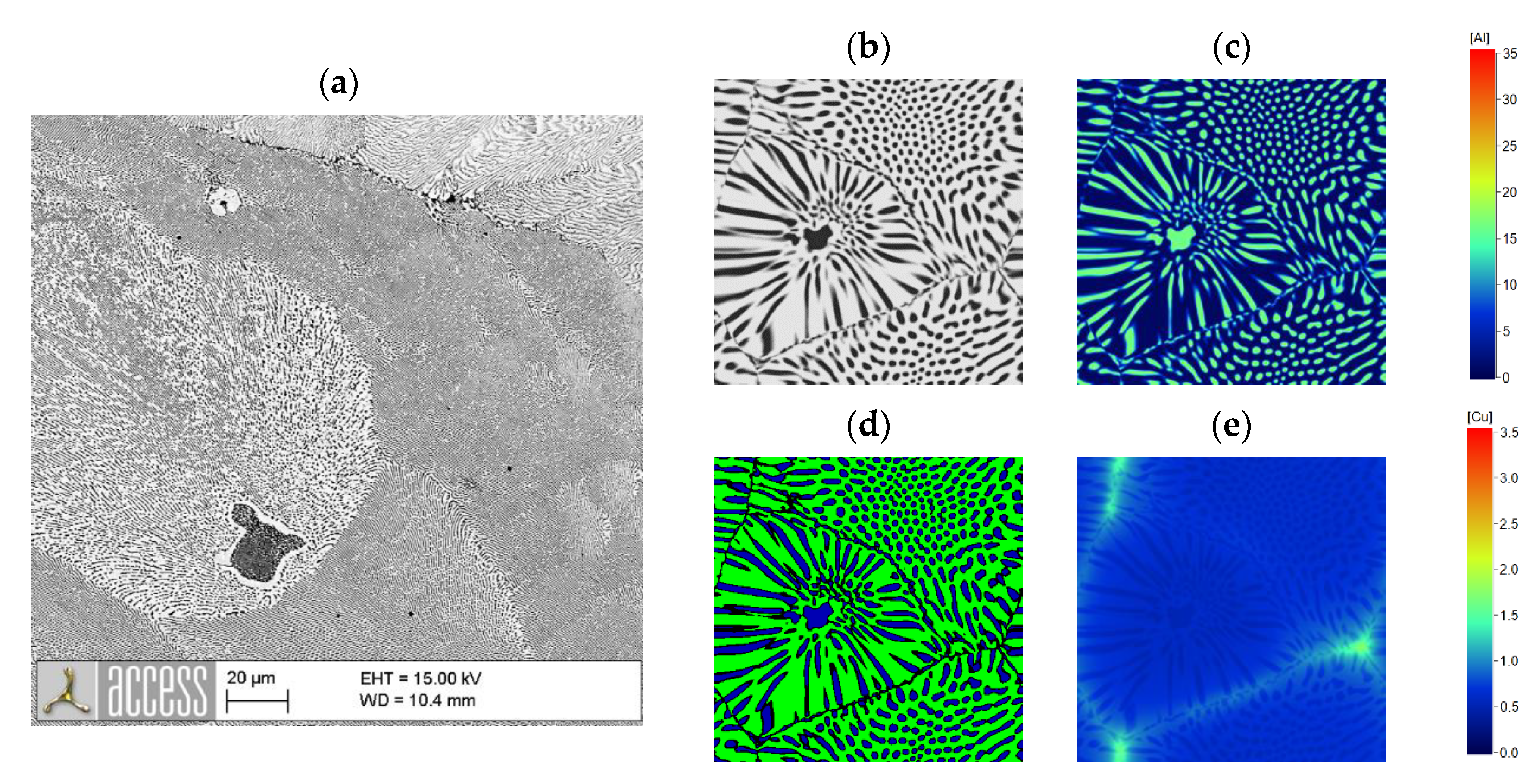
The comparison between the cast and simulated microstructures of ZnAl20Cu0.7 is shown in Figure 5. It demonstrates also for a hypereutectic alloy a good correlation between the as-cast and simulated microstructures. Both phase fractions and the shape of the phases are well represented by the simulation. Overall, the simulation calculates 82% β and 18% η. In ZnAl20Cu0.7, the β phase with local Al concentrations up to 45 wt.% in the dendrite centers is the primary phase. It decomposes into the zinc-rich η and the aluminum-rich α phases. The resulting eutectoid microstructure is not resolved in the SEM image shown in Figure 5, but the variation in the Al concentration leads to the contrast within the dendrites. The local Al concentration decreases from the center areas of the dendrites towards the outer areas that solidify last. The same distribution is obtained in the simulations. The qualitative agreement of the concentration profiles verifies that the values for the diffusion coefficients used in the simulation are at least in the right order of magnitude.
The morphology of the interdendritic eutectic exhibits a rim of η phase around the dendrites, whereas a lamellar structure can only be formed in larger interdendritic areas. The simulation also predicts this behavior. Furthermore, Cu is mainly distributed within the eutectic regions.
The microstructure of the near-eutectic alloy ZnAl5.5cu0.7 is shown in Figure 6. As already shown in Figure 3b, the solidification of this alloy takes place at 382 °C starting with the formation of small η or β nuclei which are fully surrounded by the eutectic phases. The as-cast microstructure, as well as the simulated one, again shows the same overall appearance. Both microstructures are dominated by eutectic grains. The eutectic appears lamellar or fibrous in the 2D cutting plane. The lamellar appearance is partly a geometrical effect due to the cutting, but also the 3D structures exhibit lamellar regions with a higher tendency in the last stages of solidification. Moreover, here, the simulated eutectic structure is coarser than the experimental ones. The local Cu concentration is again highest at the boundaries between eutectic grains.
For the alloys investigated in this paper, the calculated phase fractions of the β phase are compiled in Table 2 and will later be discussed for the evaluation of the hardness computation model.
The comparison between phase-field results and equilibrium calculations shows a significant difference for low and high Al contents. The deviation is most striking for the alloy with 20 wt.% Cu. According to the thermodynamic equilibrium, a single β phase is expected, however, in the experimental micrograph, a still large amount of eutectic, i.e., η phase, is present. This is also seen in the phase-field results which show 11.3% η. For lower Al contents, the equilibrium calculations underestimate the amount of β phase after solidification, also in accordance with the experimental findings.
Another advantage of quantitative phase-field simulations is evident for ZnAlCu alloys with higher copper contents. As already mentioned, ε-Zn4Cu forms at copper contents above 2 wt.%. The Zn4Cu phase can only be identified by EDS analysis with great effort. In SE and BSE contrast, there is no visible difference between the η phase and ε phase because of the similar atomic mass of Cu and Zn. Hence, the determination of the phase fractions of these two phases in an SEM analysis is accompanied by large uncertainties. With the help of phase-field simulations, phase fractions, size and distribution can be illustrated as shown in Figure 7. The figure shows a partially solidified microstructure with 62% solid fraction.
In ZnAl5.5Cu4, all three phases, β, η and ε, grow from the melt and form a ternary eutectic microstructure with predominantly ε but also smaller fractions of β as primary phases. In Figure 7, the ε phase appears red, η appears green, β appears blue and black marks the liquid. β/η eutectic islands grow in between the primary ε dendrites. In the BSE image, this corresponds to the coarse eutectic areas, e.g., in the upper left quadrant.

3.3. Hardness Measurement Results

The hardness of a material is a decisive parameter for its suitability for use as a bearing material. A good adaptation to the shaft material and a good embedding capability for wear particles are basic requirements that a bearing material must fulfil in order to prevent severe damage to the shaft and bearing.
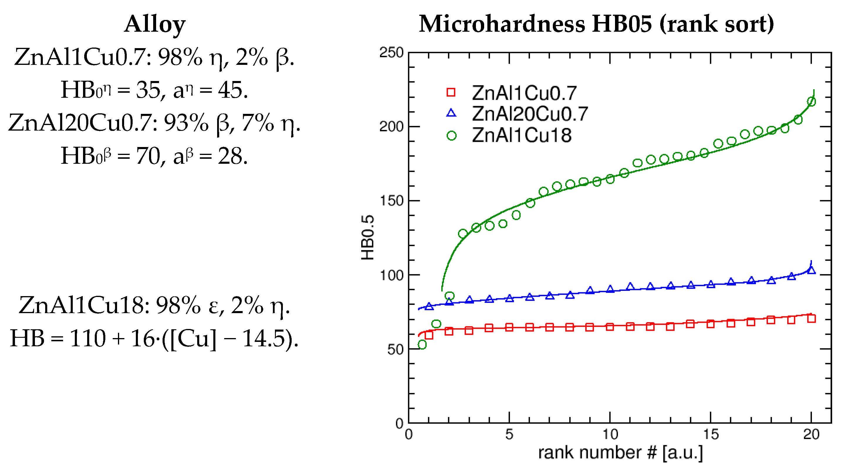
Knowledge of possible correlations between alloy composition and material hardness, both at the macroscopic and microscopic level, is therefore essential. Results from microhardness measurements of alloys that predominantly solidify in a single phase are shown in Figure 8, i.e., the alloy compositions are in the single-phase regions of the equilibrium phase diagram. The hardness values were measured at arbitrary positions on the samples, with approximately 0.5 mm distance between two indents. In the plot, the values are sorted by size (rank sort), therefore the plot does not show any correlation of the hardness with its location in the microstructure—it is a solely statistical analysis. The solid curves are calculated values based on the Cu microsegregation as derived from the phase-field simulation. We suggest a correlation between the hardness and the local Cu concentration following the relationship HBi = HB0i + ai·[Cu]i, where HB0i is the hardness of phase i with zero Cu. For the ε-phase CuZn4, the dependence from the Cu concentration is attributed to the difference from the reference concentration [Cu]0ε, thus the hardness model reads: HBε = HB0ε + aε·([Cu]ε − [Cu]0ε). The experimental data for ZnAl1Cu18 show data points with low hardness values. These points can be attributed to indents, which are in microstructure regions that show residual amounts of the η phase.
Experimentally, it would be a large effort to measure the local Cu concentration, whereas it is a direct result from the simulation. The variation in the computed hardness values, again sorted from minimum to maximum, reflects the distribution of local Cu concentrations in the simulation domain. The good match of the model data with the experimental distribution is evidence that the hardness in all three phases, η, β and ε, depends on the (local) Cu concentration. For η in ZnAl1Cu0.7 and β in ZnAl20Cu0.7, the Cu concentration is below the solubility limit at solidus temperature and the samples were measured in the as-cast state, i.e., without any subsequent heat treatment. Therefore, it is likely that, at least partially, the impact of Cu on hardness is caused by solid solution strengthening, as has already been reported by Savaskan et al. [5,11,23].
From the diagram and the modeling, one can infer that η is the phase with the lowest hardness, and ε is the one with clearly the highest hardness. One should keep in mind that β decomposes into η and α’ via a eutectoid reaction, thus the hardness values for β should be considered rather as an effective value for a composite structure and not as a value for a single phase.
In the following, we will discuss the measured macroscopic Brinell hardness from the as-cast samples and show that the data follow a simple mixture rule. The macroscopic hardness was determined by Brinell hardness measurement HBW10-2.5/62.5/15. The measured hardness for alloys with different aluminum contents and thus different β-phase contents is shown in Figure 9. As was to be expected from the results of the microhardness measurements, an increase in the β-phase content leads to an increase in the macroscopic hardness. Extrapolating the hardness to a complete β-phase sample yields 117 HB. The values from the microhardness measurements are systematically below the values from a macroscopic indent. We attribute this to a different deformation behavior on the different scales.
The hardness increases monotonously with the β-phase fraction. Except from the alloy with 2% Al, the hardness follows a linear relationship: HB = f η · HB η + f β · HB β , where f i is the phase fractions and HB i is the hardness of the individual phases, in this case with 0.7 wt.% Cu. The calculated curve in Figure 9 is based on HB η = 72.5 and HB β = 117.5 .
The dependency of macroscopic hardness on copper content shows a nonlinear behavior, as can be seen for the macroscopic hardness of ZnAl5.5CuX shown in Figure 10. In the range below 1.5 wt.% copper, barely any formation of the ε phase takes place, but the hardness increases from 72 to 98 HB. Again, this increase can be attributed to solid solution hardening. For Cu concentrations below 1.5 wt.%, the phase fractions of β and η only weakly change for different Cu concentrations and we can describe the hardness by the relation HB = ( f η · HB η + f β · HB β ) + a·[Cu], where a = 21.4/wt.%. The hardness of a Cu-free ZnAl5.5 alloy with 33% β and 67% η would be less than 70 HB.
For Cu concentrations above 1.5 wt.%, the ε phase becomes stable and its amount then increases linearly with the Cu concentration. The formation of ε gives an upper limit for Cu in solid solution and therefore for the hardness of the β/η microstructure. The microhardness measurements for ZnAl1Cu18 prove that the ε phase is considerably harder than β and η with a noticeable effect on the macroscopic hardness. An even small increase in Cu from 1.4 to 3 wt.% increases the phase fraction of ε from 0 to 13% with a corresponding hardness increase from 98 to 110. Again, it can be described by a linear relationship of the form HB = ( f η · HB η + f β · HB β ) max + a·[Cu-1.4], where a = 6.25/wt.% and the constant offset ( ) m a x = 102.5.
Higher phase fractions of the ε phase are not desirable in plain bearing applications due to the brittle and abrasive effect.

4. Summary

As shown in the results, spatially resolved phase-field simulations could provide good correlations with the as-cast microstructures of a variety of ZnAlCu bearing alloys. The comparison between the simulation and microscopic analysis of casted alloy samples demonstrates that simulations can be used to predict the microstructure of alloys in the ternary Zn-Al-Cu system in the range of [Al] = 0–25 wt.% and [Cu] = 0–20 wt.%. Furthermore, the macroscopic hardness correlates with the microstructure, in particular with the phase fractions and the Cu concentration. Results from a simple model based on mixture rules are in good agreement with the measured values, especially for variations in aluminum content which determines the β-phase fraction. Cu has apparently two different effects: it strengthens the individual phases by solid solution hardening and above 1.4 wt.%, it leads to the formation of ε-Cu4Zn which shows more than two times larger hardness values compared to β and η.

Author Contributions

Conceptualization, casting and mechanical tests were performed by S.G.; methodology, visualization and simulation were carried out by M.A.; supervision and project administration by A.B.-P. All authors have read and agreed to the published version of the manuscript.

Funding

The presented results are derived from IGF project 20165 N of the “FVA Research Association of the Drive Technology” which was funded within the scope of joint collaborative program “IGF” by the Federal Ministry for Economic Affairs and Energy, following a decision of the German Bundestag.

Conflicts of Interest

The authors declare no conflict of interest.

References

  1. Czichos, H.; Habig, K. Tribologie Handbuch.Tribometrie, Tribomaterialien, Tribotechnik; Springer Fachmedien: Wießbaden, Germany, 2015. [Google Scholar]
  2. Savaskan, T.; Murphy, S. Sliding wear of cast zinc-based alloy bearings under static and dynamic loading conditions. Wear 2002, 252, 693–703. [Google Scholar] [CrossRef]
  3. Li, H.; Liu, Y. Effect of zirconium on the microstructure and mechanical properties of Zn–4%Al hypoeutectic alloy. J. Alloy. Compd. 2014, 592, 127–134. [Google Scholar] [CrossRef]
  4. Zhang, L.; Chen, M. Structure and properties of an as-cast zinc-based alloy with high strength and wear resistance. J. Mater. Sci. Lett. 1998, 17, 1903–1905. [Google Scholar] [CrossRef]
  5. Savaskan, T.; Hekimoglu, A. Microstructure and mechanical properties of Zn–15Al-based ternary and quaternary alloys. Mater. Sci. Eng. A 2014, 603, 52–57. [Google Scholar] [CrossRef]
  6. Choudhury, P.; Das, S. Effect of Ni on the wear behavior of a zinc-aluminum alloy. J. Mater. Sci. 2002, 37, 2103–2107. [Google Scholar] [CrossRef]
  7. Dorantes-Rosales, H.; Victor, M. Microstructure characterization of phase transformations in a Zn–22 wt%Al–2 wt%Cu alloy by XRD, SEM, TEM and FIM. J. Alloy. Compd. 2000, 313, 154–160. [Google Scholar] [CrossRef]
  8. Mojaver, R.; Shahverdi, H. Relationship between cooling rate, microstructure features and wear behavior in end-chill cast Zn–27%Al alloys containing more than 2% Cu. Wear 2011, 271, 2899–2908. [Google Scholar] [CrossRef]
  9. Jareno, E.; Castro, M. The effects of Cu and cooling rate on the fraction and distribution of epsilon phase in Zn–4Al–(3–5.6)Cu alloys. J. Alloy. Compd. 2010, 490, 524–530. [Google Scholar] [CrossRef]
  10. Savaskan, T.; Pürcek, G. Effect of copper content on the mechanical and tribological properties of ZnAl27-based alloys. Tribol. Lett. 2003, 15, 257–263. [Google Scholar] [CrossRef]
  11. Liang, S.; Schmid-Fetzer, R. Thermodynamic assessment of the Al-Cu-Zn system, part III: Al-Cu-Zn ternary system. CALPHAD 2016, 52, 21–37. [Google Scholar] [CrossRef]
  12. Zhu, Y. Phase transformations of eutectoid Zn-Al alloys. J. Mater. Sci. 2001, 36, 3973–3980. [Google Scholar] [CrossRef]
  13. Zhu, Y.; Lee, W. Tensile deformation-induced phase transformation in cast Zn–Al-based alloy (ZnAl7Cu3). Mater. Res. Bull. 2003, 38, 1851–1858. [Google Scholar] [CrossRef]
  14. Krupinski, M.B.K. Influence of cooling rate on crystallisation kinetics on microstructure of cast zinc alloys. J. Therm. Anal. Calorim. 2014, 118, 1361–1367. [Google Scholar] [CrossRef] [Green Version]
  15. Petzow, G. Metallographisches Ätzen 5. Auflage; Borntraeger Verlag: Berlin, Germany, 1976. [Google Scholar]
  16. ACCESS. Available online: www.micress.de (accessed on 29 May 2020).
  17. Böttger, B.; Eiken, J. Phase-field simulation of microstructure formation in technical castings—A self-consistent homoenthalpic approach to the micro–macro problem. J. Comput. Phys. 2009, 228, 6784–6795. [Google Scholar] [CrossRef]
  18. Böttger, B.; Apel, M.; Budnitzki, J.; Eiken, G.; Laschet, G.; Zhou, G. Calphad Coupled Phase-field Model with Mechano-Chemical Contributions and its Application to Rafting of γ’ in CMSX-4. Comput. Mater. Sci. 2020, 184, 109909. [Google Scholar] [CrossRef]
  19. Böttger, B.; Eiken, J. Phase field simulation of equiaxed solidification in technical alloys. Acta Mater. 2006, 54, 2697–2704. [Google Scholar] [CrossRef]
  20. Böttger, B.; Eiken, J.; Apel, M. Multi-Ternary Extrapolation Scheme for Efficient Coupling of Thermodynamic Data to a Multi-Phase-Field Model. Comput. Mater. Sci. 2015, 108, 283–292. [Google Scholar] [CrossRef]
  21. Carré, A.; Böttger, B.; Apel, M. Implementation of an antitrapping current for a multicomponent multiphase-field ansatz. J. Cryst. Growth 2013, 380, 5–13. [Google Scholar] [CrossRef]
  22. Eiken, J. Numerical solution of the phase-field equation with minimized discretization error. In Numerical Solution of the Phase-Field Equation with Minimized Discretization Error; IOP Publishing Ltd.: Bristol, UK, 2012. [Google Scholar]
  23. Savaskan, T.; Hekimoglu, A. Relationships between mechanical and tribological properties of Zn-15Al alloys. Int. J. Mater. Res. 2016, 107, 646–652. [Google Scholar] [CrossRef]
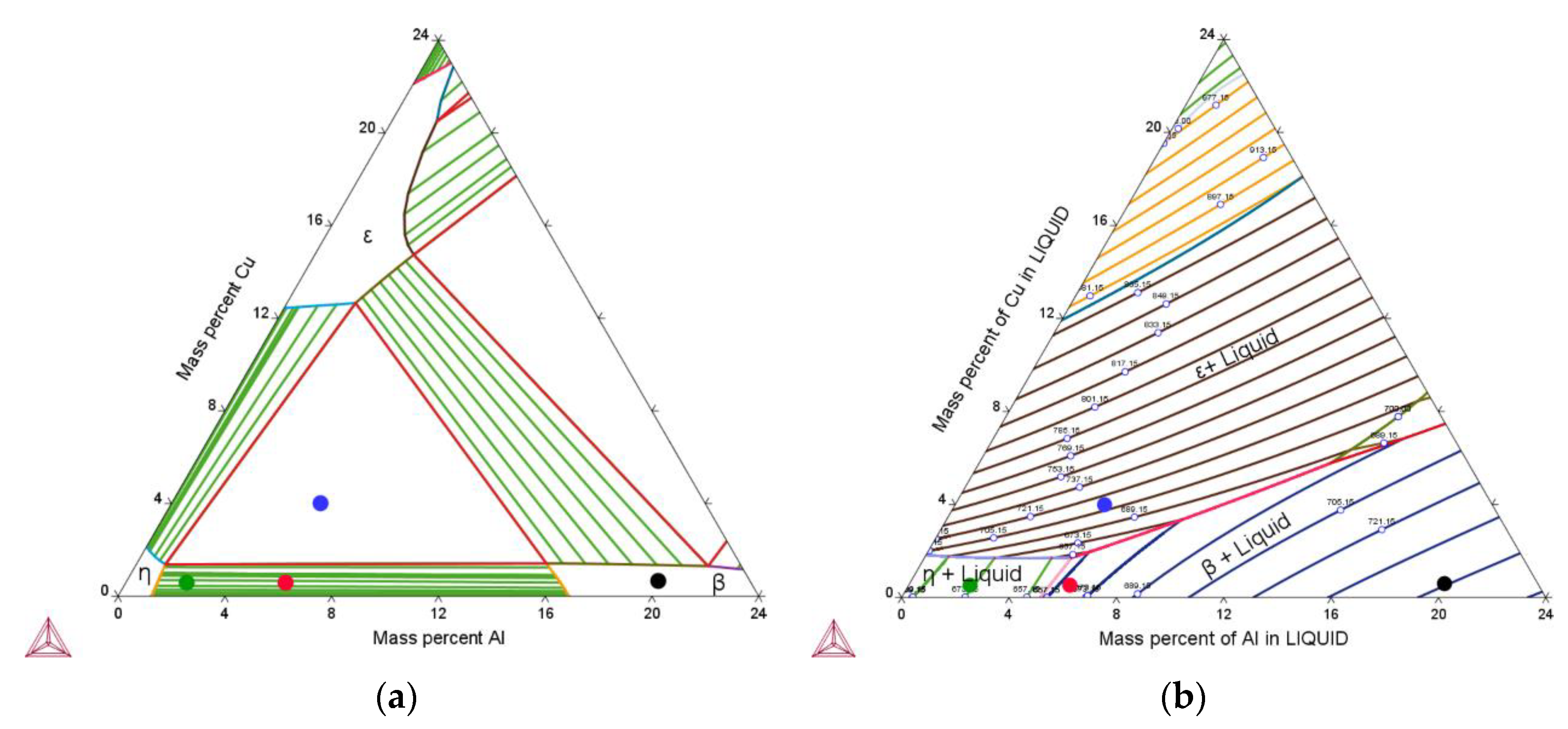
Figure 1. Computed isothermal section at T = 375 °C of the Zn-rich Zn-Al-Cu phase diagram based on the CALPHAD data from [9] (a). The four different alloy compositions investigated in this paper are marked by the filled circles. Computed liquidus projection (b).
Metals 10 01659 g001
Figure 2. Microstructure evolution in Zn20Al0.7Cu during solidification represented by the Al concentration. Size of the 2D cutting plane in the middle of the 3D box: 100 µm × 100 µm.
Metals 10 01659 g002
Figure 3. (a) Phase fractions versus temperature for three alloys with different Al compositions (β denotes the fcc-phase, η the hcp-Zn phase). (b) Temperature versus time for the three alloys as derived from the simulations.
Metals 10 01659 g003
Figure 4. (a) Microstructure of ZnAl2Cu0.7 in backscattered electrons (BSE) contrast; (be) simulated microstructure of ZnAl2Cu0.7. (b) Al (gray scale, matched contrast), (c) Al concentration (wt.%), (d) phases (η green, β blue) and (e) Cu concentration (wt.%). Size of the 2D plane from the simulation: 100 µm × 100 µm.
Metals 10 01659 g004
Figure 5. (a) Microstructure of ZnAl20Cu0.7 in BSE contrast; (be) simulated microstructure of ZnAl20Cu0.7. (b) Al (gray scale, matched contrast), (c) Al concentration (wt.%), (d) phases (η green, β blue) and (e) Cu concentration (wt.%). Size of the 2D plane from the simulation: 100 µm × 100 µm.
Metals 10 01659 g005
Figure 6. (a) Microstructure of ZnAl5.5Cu0.7 in BSE contrast; (be) simulated microstructure of ZnAl5.5Cu0.7. (b) Al (gray scale, matched contrast), (c) Al concentration (wt.%), (d) phases (η green, β blue) and (e) Cu concentration (wt.%). Size of the 2D plane from the simulation: 100 µm × 100 µm.
Metals 10 01659 g006
Figure 7. (a) Microstructure of ZnAl5.5Cu4 in BSE contrast. Simulated microstructure of ZnAl5.5Cu4; (b) Al (grey scale, matched contrast), (c) Al concentration (wt.%), (d) phases (η green, β blue, ε red) and (e) Cu concentration (wt.%). Size of the 2D plane: 100 µm × 100 µm.
Metals 10 01659 g007
Figure 8. Measured and simulated microhardness for as-cast samples. In the left column, the phase fractions after solidification as derived from the simulations and the parameters for the hardness model are shown.
Metals 10 01659 g008
Figure 9. Macroscopic hardness of ZnAlxCu0.7 alloys for different β-phase fractions, i.e., different Al compositions.
Metals 10 01659 g009
Figure 10. Hardness and ε-phase fraction of ZnAl5.5Cux for different Cu concentrations.
Metals 10 01659 g010
Table 1. Material parameters used for the phase-field simulations.
Diffusion CoefficientsInterfacial Energy
Al in melt2 × 10−6 cm2/ssolid phases/melt2.5 × 10−5 J/cm2
Cu in melt2 × 10−6 cm2/ssolid/solid interfaces2.5 × 10−5 J/cm2
Al in all solid phases3.1 × 10−9 cm2/sinterfacial anisotropies
Cu in all solid phases3.1 × 10−9 cm2/sβ-Al (Zn-rich)cubic
--η-Zn and ε-Zn4Cuhexagonal
Interface mobility for solid/melt interfaces∞ according to the thin interface limit [21]
Table 2. β-phase fractions at 375 °C representing the as-cast phase fraction immediately after solidification for alloys with different aluminum concentrations.
Alloyβ Phase (Simulation) [%]β Phase (Equilibrium) [%]
ZnAlCu0.72.00
ZnAl2Cu0.78.06.6
ZnAl4Cu0.721.821.8
ZnAl5.5Cu0.732.932.8
ZnAl11Cu0.769.769.6
ZnAl20Cu0.788.7100
Publisher’s Note: MDPI stays neutral with regard to jurisdictional claims in published maps and institutional affiliations.