Article

Effect of Film-Forming Amines on the Acidic Stress-Corrosion Cracking Resistance of Steam Turbine Steel

1
Department of Materials, Textiles and Chemical Engineering, Research Unit Sustainable Materials Science, Ghent University, Technologiepark 46, 9052 Zwijnaarde, Belgium
2
Department of Green Chemistry and Technology, Ghent University, Coupure Links 653, 9000 Ghent, Belgium
3
Kurita Europe GmbH, Niederheider Straße 22, D-40589 Düsseldorf, Germany
4
Department of Applied Physics, Research Unit Plasma Technology, Ghent University, Sint-Pietersnieuwstraat 41, 9000 Ghent, Belgium
*
Authors to whom correspondence should be addressed.
Metals 2020, 10(12), 1628; https://doi.org/10.3390/met10121628
Submission received: 16 October 2020 / Revised: 15 November 2020 / Accepted: 23 November 2020 / Published: 4 December 2020
(This article belongs to the Special Issue Localized Corrosion of Metals and Alloys)

Abstract

:
This work evaluates the effect of film-forming amines (FFA) on the acidic stress-corrosion cracking (SCC) resistance of NiCrMoV turbine steel. Contact angle measurements show an increased hydrophobicity of the surface when coating the steel with oleyl propylene diamine (OLDA). According to potentiodynamic measurements and post-mortem scanning electron microscopy (SEM) analysis, anodic dissolution and hydrogen embrittlement still occur when the steel is FFA coated. In situ constant extension rate testing (CERT) in acidic aqueous environment at elevated temperature of FFA-coated steel shows a ductility gain compared to non-coated steel, explained by a decrease in both corrosion rate and hydrogen uptake.

Graphical Abstract

1. Introduction

Appropriate control of the water chemistry is of major importance in steam-driven power plant operation. Several chemical treatments have been developed to maintain a stable material–environment interaction, as such minimising corrosion and fouling of the materials used in these plants. A short overview of different chemical treatments used in steam-water cycles is presented here to introduce the use of film-forming amines (FFA). Thereafter, the need to investigate the influence of FFA on the resistance to acidic stress-corrosion cracking (SCC) of steam turbines is demonstrated.
Originally, as boiler feedwater chemical treatment, the pH was controlled by the addition of ammonia or alkalising amines, realising an alkaline environment, to counter acidic conditions where rapid corrosion is promoted by deteriorating the natural protective oxide layer of the metal [1]. When ammonia/alkalising amines are combined with the removal of oxygen—the corrosion rate depends on the oxygen content—by addition of oxygen scavengers such as hydrazine, the chemical treatment is called all-volatile treatment (reducing) (AVT(R)) [1,2]. However, the reducing environment typically leads to a porous magnetite (Fe3O4) layer that promotes flow accelerated corrosion (FAC, a corrosion mechanism in which the natural protective oxide layer of the metal dissolves in the fast flowing water, followed by corrosion of the underlying metal to recreate the oxide, as such leading to a continuous metal loss), as was determined for the first time at the Surry Nuclear Power Station in 1986 [3,4,5]. On the other hand, with all-volatile treatment (oxidising) (AVT(O)) or oxygenated treatment (OT), oxygen is allowed or even injected into the water to form a protective and less soluble layer of iron oxide-hydroxide (FeOOH) or hematite (Fe2O3) on top of the magnetite, as such increasing the FAC resistance [2,4,5,6,7,8]. Nevertheless, the formation/fouling of insulating oxide layers is known to deteriorate the heat transfer efficiency and, therefore, the performance of the entire steam-water cycle [9]. To anticipate on efficiency losses, the steam-water installation is nowadays periodically cleaned. In order to reduce periodic shutdowns, the system can be dosed with polymeric dispersants, which have proven to be effective in avoiding fouling in several systems [9,10,11].
The use of phosphates, another type of water treatment practice, was developed since ammonia loses its ability to increase the pH at higher temperatures because of its poor alkalising properties [12]. Sodium phosphates are strong alkalisers, as such also providing an optimal pH at higher temperature, which is necessary to minimize corrosion of the material. In addition, sodium phosphates accelerate oxygen scavenger reactions and serve as a chelating agent for calcium and magnesium ions in order to avoid extensive scaling [13]. Scale accumulation can cause major problems in the boiler since such scale formation typically acts as an insulator, which can result in (local) overheating of the boiler. By chelating scaling ions, a sludge is formed that can easily be removed by blowdown [14]. However, the use of phosphates entails several corrosion issues, such as caustic gouging, caustic embrittlement, phosphate hideout and acid phosphate corrosion [5,13,15,16,17]. Therefore, dosing of phosphates as well as of caustic must be done with great care. Moreover, when overdosing, these water treatment chemicals can be transported from the boiler to the remaining of the steam-water cycle, which is called carryover. For some water treatment chemicals, such as ammonia and alkalising amines, this is desired, but for other chemicals and impurities, which can result in steam turbine fouling and significant corrosion damage, carryover must be avoided at all cost [5,12,18,19].
One way to tackle problems concerning impurities is by purifying the water before it enters the steam-water cycle [20]. However, water treatment technologies are increasingly faced with lower quality feed waters, because of among others the ongoing shift towards alternative water sources and climate change [21,22,23,24,25]. Especially the increasing amount of organic acids in the first condensate of low-pressure steam turbine sections can cause serious corrosion damage, such as SCC [26,27,28,29,30,31,32,33,34,35]. These organic acids originate from the breakdown of organic impurities by hydrothermolysis in boilers and superheaters [19,36,37,38,39,40,41]. Film-forming amines, added during operation, might also tackle the issues resulting from impurities in the water. FFA are a type of corrosion inhibitor under investigation since the 1960s [42,43]. As the name suggests, these amines are hypothesised to form a hydrophobic layer on the surface of the metal, as such providing a protective barrier between the metal and the corrosive environment [20,42,43]. van Lier et al. [44] stated that in a film-forming amine-treated steam-water cycle not only caustic gouging and acid phosphate corrosion did not occur, but also the risk of hydrogen damage was vastly reduced by the continuous removal of deposits. After all, FFA are stated to have a cleaning effect, i.e., expel ionic impurities from the surface and gradually remove loose deposits such as calcium scale or porous magnetite because of their strong affinity for the metal surface, leaving only a dense and protective magnetite layer [20,42,45,46,47,48,49]. Therefore, dosing FFA has been stated to avoid the need to periodically clean steam-water systems, as such preventing heat transfer efficiency losses [42,50]. Moreover, film-forming amines are stated to have a mitigating effect on FAC, which might be related to the reduction of the dissolution rate of the metal’s oxide layer when FFA is adsorbed on it [50,51,52,53,54,55,56,57]. The hydrophobic coating is also claimed to be able to protect the metal surface against pitting and chloride induced corrosion [42,43,49,54,58]. Because of the intermediate volatility of the FFA, the entire steam-water cycle can be protected, as confirmed by Smith et al. [48] at the Uniper power plant (UK), as such also covering the steam turbine with a hydrophobic coating that shields the turbine material from organic acids [42,54]. Moreover, the power plant tested a shutdown of one month without any loss of protection by the FFA coating, meaning that the protective layer stayed intact even when FFA dosing was interrupted [20,42,48].
Although these film-forming amines have thus been shown to form a protective layer against corrosion by adsorption on the metal surface, the exact protection mechanisms are still unknown. In addition, researchers have also claimed that FFA could increase the corrosion in steam-water cycles as these amines could be a source of corrosive organic acid formation when they thermally degrade in the boiler or superheater [42,50,59]. In addition, overdosing of FFA has to be avoided, since their physical properties induce micelle formation that begins at a critical concentration, which can lead to the formation of sticky deposits that can block filters and tubes [46,50,54]. Therefore, monitoring the formation of an FFA monolayer in the entire steam-water system is important, albeit difficult, since a direct correlation between FFA dosing and adsorption is difficult to find. This is due to the complex dependency of adsorption on several factors, such as the metal’s surface area and composition, molecular structure of the FFA, the temperature and the pH of the aqueous environment [42,47,50].
As it is well-known that presence/formation of organic acids in steam-water cycles can be an initiator of SCC—and the FFA could be a source of organic acids themselves because of thermal degradation—it is of course very interesting to assess if and how the corrosion behaviour of FFA-coated steam turbine steel is affected when the aqueous environment is acidified with organic acid. It is thus also relevant to investigate how the steel’s mechanical degradation due to acidic SCC is influenced by the presence of an FFA coating. To investigate this, a novel FFA coating set-up was developed in this study and the presence of an FFA coating on steam turbine steel was evaluated by investigating the hydrophobicity of the surface with contact angle measurements, as well as by determining the surface composition with X-ray photoelectron spectroscopy (XPS). In a next step, in situ constant extension rate tests (CERT) in acidic aqueous environment followed by post-mortem scanning electron microscopy (SEM) analysis were carried out on both non-coated and FFA-coated steam turbine steel, to evaluate the mechanical degradation due to acidic SCC. Electrochemical measurements on both non-coated and FFA-coated steam turbine steels were also performed in aqueous solutions with organic acid to further evaluate the impact of FFA on the active corrosion (inhibition) mechanism.

2. Materials and Methods

2.1. Material Characterisation and FFA Adsorption

An industrial steam turbine steel of the type 27NiCrMoV15-6 (EN 1.6957) was used for the experiments, produced by applying an industrial quench and temper (Q & T) treatment. Its composition can be found in Table 1. Representative images of the steel’s microstructure, obtained by light optical microscopy (LOM, Keyence VHX-2000E, Keyence, Osaka, Japan) and scanning electron microscopy (SEM, Quanta FEG 450—accelerating voltage of 20 kV and spot size of 5 nm) analysis, are shown in Figure 1a,b, respectively. For this, sample preparation was carried out by grinding, polishing and etching in 10% Nital. A tempered martensitic microstructure with precipitates can be observed. Details on the microstructural characterisation of this steam turbine steel can be found elsewhere [60,61].
The film-forming amine oleyl propylene diamine (OLDA) was used as FFA in adsorption experiments on the steel samples, to form a hydrophobic and protective coating [42,46,58]. Its structural formula is represented in Figure 2. OLDA has two nitrogen atoms per molecule that can adsorb on the metal surface via polar covalent bonding and has already been used in industry because of its temperature stability up to at least 500 °C [54,62].
A coating set-up was engineered to coat steam turbine samples with FFA. A schematic representation of the entire set-up can be found in Figure 3. To start the coating procedure, a solution of 5 ppm OLDA was degassed with nitrogen gas (N2). No alkalising amines were added to the solution, as such the coating of the steam turbine steel occurred at neutral pH. It has to be mentioned that an OLDA concentration of 5 ppm, which is higher than the concentration usually present in steam-water cycles (<0.3 ppm), was chosen for the sake of detectability of FFA in solution at lab scale [45,63]. Furthermore, the concentration was chosen so that the absolute quantity of FFA was high enough to ensure a complete coating of the surface. Then, the samples were placed in the coating cell, while the solution was further degassed. Finally, the solution was heated up to 90 °C and kept at this temperature for one day. A temperature of 90 °C was selected, since stress-corrosion cracks in industrial steam turbines were found at this condensation temperature [33,34,64]. To avoid evaporation and loss of the solution, a reflux condenser with water cooling was used. After coating, the samples were taken out of the coating cell, cleaned with demi water and dried.
The hydrophobicity of the FFA coating was evaluated by using contact angle measurements. For this, the static sessile drop technique was used, where a water droplet of 2 µL is placed on the surface with a syringe (Krüss Easy Drop) [65]. A high-resolution camera was positioned in side view to capture the images, on which the contact angle θ (°) was determined. Low-degree contact angles indicate a highly wettable surface, because of a good spreading of the droplet, whereas higher contact angles correspond to more hydrophobic, non-wettable surfaces, as such aiming for more corrosion resistance. In addition to a coating temperature of 90 °C, steam turbine steel samples were also coated at 60 °C for contact angle measurements to evaluate the influence of the coating temperature for a same coating time on the hydrophobicity. The mean value of at least five contact angle measurements for each condition is shown. All contact angle measurements had a maximum standard deviation of 2°.
In order to obtain well-defined quantitative information about the surface atomic composition of non-coated and coated steels, XPS measurements were carried out employing a PHI 5000 Versaprobe II spectrometer (Physical Electronics GmbH, Feldkirchen, Germany) Samples were excited, over an area of 500 × 500 µm2, with an X-ray beam having a size of 100 µm and originating from a monochromatic Al Kα X-ray source ( h ν = 1486.6 eV) operating at a power of 25 W. The resulting photoelectrons emitted from the sample surface were detected by a hemispherical analyser (Physical Electronics GmbH, Feldkirchen, Germany) positioned under an angle of 45° with respect to the specimen normal. The XPS main chamber was persistently held at a pressure below 10−7 Pa during the gauging process. Survey scans were measured at a pass energy of 187.85 eV and a step size of 0.8 eV, followed by analysis using Multipak software (v9.6, ULVAC-PHI, Inc. Chigasaki, Japan). During this analysis step, a Shirley background was considered while complying with the relative sensitivity parameters allocated by the spectrometer manufacturer. The whole binding energy scale was calibrated in accordance with the hydrocarbon peak of the C1s spectrum being at 285 eV. In this study, the reported values are equal to the average of four values derived from the assessment of four random surface areas per condition.

2.2. SCC-Induced Mechanical Behaviour

The impact of an FFA coating on the mechanical degradation of NiCrMoV steam turbine steel due to acidic SCC was determined by comparing in situ CERT performed on non-coated tensile samples with coated tensile samples, both subjected to an acidic aqueous environment of 0.01 M acetic acid in demineralised water at 90 °C (pH = 3.5, conductivity = 250 µS/cm). pH and conductivity values were calculated. In addition, the conductivity was confirmed by experimental measurements (WTW conductivity probe LR 925/01-P IDS). Acetic acid was selected to acidify the aqueous environment since this organic acid has been reported to be (one of) the main contributor(s) of the organic acids found in steam-water cycles [35,36]. A concentration of 0.01 M acetic acid was used, slightly higher than typically measured in normal first condensates, to take deviations in water quality into account, as discussed above [9,10,11,20,21,22,23,24,25,66]. A working temperature of 90 °C was used for the same reason as for selecting the coating temperature, i.e., because of the occurrence of stress-corrosion cracks at this condensation temperature in industry [33,34,64].
Steam turbine steel was machined into tensile samples with a geometry as shown in Figure 4 and a thickness of 1.5 mm [61]. The loading direction of the tensile samples is indicated with LD, whereas the normal direction (ND) is the direction perpendicular to the top surface (ND-plane), complemented with the transverse direction (TD) for sake of orthogonality. The surfaces and edges were ground and polished for post-mortem SEM analysis. Tensile samples were coated in 5 ppm OLDA for one day at 90 °C by following the FFA coating methodology described in the previous section. In situ tensile tests were performed at a strain rate of 10−6 s−1, by making use of an Instron 5800 tensile testing machine equipped with a 100 kN load cell and a tensile testing cell developed to provide the desired acidic aqueous environment [67]. Details on the in situ CERT set-up as well as on the method development can be found in previous work [68,69].
The ductility variation from one situation to another can be expressed according to Equation (1):
%   ductility   variation = ( ε f , 2 ε y , 2 ε f , 1 ε y , 1 1 ) · 100 %
where, ε f is the engineering strain at fracture and ε y is the engineering strain at the yield strength, determined at 0.2% offset. Each condition was tested multiple times to confirm reproducibility, within 1% deviation in ductility variation, for which the methodology was developed in [70]. For the sake of clarity, only one representative engineering stress–strain curve is shown.
Fractographic and crack analysis was performed by SEM, to obtain information on the fracture mechanisms that take part both without and with FFA coating. For this purpose, the top surfaces (ND-planes) as well as the fractured surfaces (LD-planes) were examined. For SEM analysis, a Quanta 450 (FEI-Thermo Fisher Scientific, Waltham, Massachusetts, USA) and a JSM-7600F (JEOL, Akishima, Tokio, Japan) with field emission gun (FEG) were used with a spot size of 5 nm and an accelerating voltage of 20 kV. Additionally, the reduction of area (% RA) was investigated by measuring both the initial area ( A 0 ) and the area after fracture ( A f ), according to Equation (2):
%   RA = ( 1 A f A 0 ) · 100 %

2.3. Electrochemical Measurements

To study the effect of an FFA coating on the corrosion behaviour of the steam turbine steel, potentiodynamic measurements were performed on both non-coated and coated NiCrMoV steel samples, in different concentrations of acetic acid. The following concentrations were tested: 0, 0.0001, 0.001, 0.01, 0.1, 1 M acetic acid in demineralised water at a temperature of 90 °C. Again, the choice of working with acetic acid as organic acid and a temperature of 90 °C is based on industrial relevance [33,34,35,36,64]. Polarisation curves were obtained by using a three-electrode system and a potentiostat (Ivium CompactStat.h). Working electrode (WE), counter electrode (CE) and reference electrode (RE) were the steam turbine steel, a platinum gauze and a leakless Ag/AgCl electrode, respectively. Potentiodynamic measurements were performed after submersion of the steel for 24 h in the solution, which was believed to be sufficient to reach a steady state potential. A scan rate of 5 mV/s was applied. Multiple potentiodynamic measurements were performed until a maximum standard deviation of 10 mV for the corrosion potential E corr (V vs. SHE) was obtained. Corrosion rates CR (µm/year) were determined according to the method described in previous work [69].

3. Results and Discussion

3.1. Surface Analysis

The effect of the FFA coating on the NiCrMoV steam turbine steel’s hydrophobicity was tested by determining the contact angle between the material and a water droplet. Figure 5 shows how the droplet’s shape on the surface changes with coating temperature. Figure 5a shows that the bare metal has a contact angle of approximately 36°. Applying an FFA coating at 60 °C, cf. Figure 5b, resulted in an increase of the contact angle to 77°, indicating a more hydrophobic surface. At a higher coating temperature of 90 °C, the contact angle reached 96°, cf. Figure 5c. Comparable values were found for a low carbon steel coated with octadecylamine (ODA) by Baux et al. [71]. These results show that the hydrophobicity of the surface increased with a higher coating temperature for the same coating time, as such indicating an improved protection against harmful environments, based on the wettability. Therefore, samples were coated in 5 ppm OLDA for one day at 90 °C, for all coated samples discussed further on in this work.
In fact, the amino group of the FFA is hydrophilic, whereas the nonpolar alkyl chain is a hydrophobic tail. After all, FFA are amphiphilic, i.e., partly hydrophilic (polar) and partly hydrophobic (non-polar), like detergents and soaps (cf. cleaning effect) [20,42,45,46,47,48,49]. Chemisorption by polar covalent bonding between the lone electron pair on the amino group and the partially vacant d-orbital of iron, combined with hydrogen bonding between a lone electron pair on oxygen of a (hydr) oxidised steel surface and the antibonding molecular orbital of a bond between hydrogen and the more electronegative nitrogen atom of the amino group, results in a strong adsorption on the surface [42,72,73,74]. Because of interaction between the amino groups and the metal surface, as well as van der Waals forces amongst the alkyl chains, the hydrophobic tails are pointed away from the surface. FFA with more than one amino group per molecule, such as OLDA, can have multiple nitrogen-iron bonds with the surface, which makes the adherence of the coating better [9,42]. However, according to Foret et al. [58], the more amino groups on the FFA, the more difficult to form a homogeneous coating because of a possible steric hindrance.
The surface atomic composition of both non-coated and FFA-coated NiCrMoV steam turbine steel, obtained by XPS, is given in Table 2. A significant increase in both carbon and nitrogen content is observed when coating the steel: the carbon content more than doubled from 30.9 to 71.5 at.%, whereas the nitrogen content increased more than seven times, i.e., from 0.5 to 3.6 at.%. The relatively high amount of carbon found on the surface of the non-coated steel is due to adsorbed carbon contamination, as reported by Cools et al. [75]. The increase in both carbon and nitrogen content for the coated steel, proves the presence of an FFA layer on the steel, cf. the elemental composition of OLDA (Figure 2). By applying an FFA coating, a decrease in the amount of iron is also observed, as well as in the steel’s alloying elements nickel, chromium and molybdenum (cf. Table 1), and the oxygen concentration, as can be seen in Table 2. As such, the FFA coating protects the steel by exposing less of the original surface, including the metal’s oxide layer, to the environment. As described by Topp [76], oxide formation was, thus, not totally prevented by the application of the FFA coating. In Figure 6, XPS overview scan spectra of both non-coated and FFA-coated NiCrMoV steam turbine steel are shown. It can be seen that the peaks corresponding with carbon and nitrogen have increased, whereas the others have decreased by coating the steel with FFA. Smith et al. [48] reported a similar XPS spectrum of a tube sample from a steam-water cycle exposed to an FFA treatment, where the N1s peak maximum was situated at about 399.5 eV.
Normally, FFA are injected to the steam-water cycle in combination with (i) stabilising agents, which are amongst other hydrotropic species that increase the solubility of the FFA in the water by micellisation, and (ii) alkalising amines, to control the pH of the system, since FFA themselves barely change the pH because of their low concentration [43,50,77]. A more alkaline pH promotes the formation of metal oxides, on which FFA would preferably adsorb since hydrogen bonds can be formed in addition to nitrogen–iron bonds [46]. In contrast to the reported requirement of controlling a well-defined alkaline pH range for the formation of FFA coatings, this study shows that an FFA coating can also be applied at neutral pH [42].

3.2. SCC-Induced Mechanical Behaviour

Engineering stress–strain curves of both non-coated and FFA-coated steam turbine NiCrMoV steel were obtained by performing in situ CERT in acidic aqueous environment and are shown in Figure 7. Because of the presence of the FFA coating, a slight increase in strength and a significant increase in ductility can be observed. Coating the steam turbine steel with FFA resulted in a ductility gain of 13% with respect to the non-coated steel.
When examining the fracture surface of the non-coated NiCrMoV steel tested in acidic aqueous environment by SEM, both ductile regions and more brittle zones were observed, as shown in Figure 8 [61]. On the fracture surface, cf. Figure 8a, a lot of dimples, formed because of ductile microvoid coalescence, can be seen. At the walls of the large dimples, slip traces of deformation in a stairs-like structure, often referred to as serpentine glide, formed by glide plane decohesion, can be observed [78,79]. In addition, more embrittled regions were found close to the edge of the fracture surface, cf. Figure 8b. At these regions, cracks were observed, as shown in Figure 8c. As can be seen in Figure 9, indeed, smaller secondary cracks were present close to the main crack that were not present in the rest of the gauge length [61]. This indicates that these cracks were formed because of strain localisation around the main crack at ultimate tensile strength (UTS) and not due to subcritical cracking [68,80]. Since these cracks are only present when having a combination of high local stresses and a corrosive environment, these cracks are presumably the result of SCC [61,68,69].
Similar fracture characteristics were observed at the fracture surface of the FFA-coated NiCrMoV steel tested in the corrosive environment, as can be seen in Figure 10. Again, mainly ductile dimples were found (cf. Figure 10a) and a more embrittled fracture surface showing stress-corrosion cracking was detected near the edge (cf. Figure 10b). As shown in Figure 11, similar secondary stress-corrosion cracks were observed on the top surface of the FFA-coated steam turbine steel tensile tested in corrosive environment. Therefore, the presence of the FFA coating seems to have no significant impact on the fracture characteristics, nor on the presence of secondary cracking, in acidic aqueous environment. However, when calculating the reduction of area for both conditions, % RA is equal to 27% for the non-coated steel, whereas a % RA of 38% was obtained for the FFA-coated steel. This indicates that more necking occurred, as such corresponding with a more ductile fracture behaviour, when an FFA coating was present on the steel. The higher amount of necking can also be seen in Figure 12, when comparing the fracture surface of coated steel (cf. Figure 12b) with that of the non-coated steel (cf. Figure 12a). These results are in accordance with the longer necking part of the engineering stress–strain curve of the FFA-coated steel compared to that of the non-coated steel, cf. Figure 7.

3.3. Evaluation on the Active Mechanism of Corrosion

Electrochemical measurements were performed to determine which reactions take place when bringing both the non-coated and the FFA-coated steam turbine steel into contact with acidic aqueous environments, of 0, 0.0001, 0.001, 0.01, 0.1 and 1 M acetic acid in demineralised water, at an elevated temperature of 90 °C. Representative polarisation curves at these conditions are given in Figure 13. Potentials E (V vs. SHE) are plotted versus their current density j (µA/cm2). Representative electrochemical data is given in Table 3.
Subsequently, corrosion potentials E corr (V vs. SHE) for both non-coated and FFA-coated NiCrMoV steel were determined and are shown in Figure 14, a Pourbaix diagram of iron in water at 90 °C with molality 1, based on thermodynamic data from FactSage© [81,82,83,84,85]. All corrosion potentials are lying above the iron oxidation line, cf. Equation (3), meaning that oxidation of the steel takes place as anodic reaction in all conditions.
Fe Fe 2 + + 2 e
Based on the thermodynamically stable iron states in Figure 14, above a pH of around 4.2, the steel is thermodynamically promoted to form Fe2O3, whereas at lower pH, dissolution as Fe2+ is favoured. When the NiCrMoV steel is coated with FFA, the corrosion potentials above a pH of around 4.2 are shifted upwards with respect to the non-coated conditions, as such showing a less reactive (more noble) behaviour when FFA coated. On the other hand, the corrosion potentials at lower pH are unaffected when comparing FFA-coated with non-coated conditions. As a result, in such acidified conditions for both FFA-coated and non-coated steels, the driving force of the reactions taking place Δ G (J/mol), cf. Equation (4) ( E 0 (V) is the equilibrium potential), is expected to be similar.
Δ G = nF ( E 0 ,   reduction E 0 ,   oxidation )
Furthermore, it is noticed that all corrosion potentials are situated below the oxygen reduction reaction line, according to Equation (5), meaning that oxygen reduction takes place in every acidic aqueous environment.
O 2 + 4 H + + 4 e 2 H 2 O
In contrast, corrosion potentials above a pH of around 4.2 are located above the hydrogen reduction reaction line, according to Equation (6) (Volmer reaction), as such promoting hydrogen atoms to oxidise back to hydrogen protons, whereas at lower pH, corrosion potentials are below the hydrogen reduction reaction line, as such favouring hydrogen proton reduction to hydrogen atoms [86,87].
H + + e H
When the formation of hydrogen atoms is thermodynamically stable, they can recombine by chemical desorption, according to Equation (7) (Tafel reaction), or by electrochemical desorption, according to Equation (8) (Heyrovsky reaction), as well as absorb into the steel, cf. Equation (9), as such causing hydrogen embrittlement [80,86,87,88,89,90].
2   H ads   H 2
H ads   +   H +   +   e     H 2
H ads   H abs
Based on the location of the corrosion potentials with respect to the reduction reaction lines, applying an FFA coating on the NiCrMoV steam turbine steel does not lead to a change in active mechanisms compared to non-coated steel in the different acidic aqueous environments. Nevertheless, the corrosion rates might have been influenced by coating the steam turbine steel with FFA, regardless of showing a similar driving force for the reactions to take place.
Indeed, lower corrosion rates are observed for the FFA-coated steel compared to non-coated NiCrMoV steel, even at high acetic acid concentrations, as can be seen in Figure 15. In this figure, the corrosion rate is plotted as a function of the hydrogen proton concentration, for both non-coated and FFA-coated NiCrMoV steam turbine steel tested at 90 °C. Without coating, the NiCrMoV steel shows a linear relationship between corrosion rate and hydrogen proton concentration, according to Equation (10) [61].
CR = a · [ H + ] + b
When applying an FFA coating on the steam turbine steel, again a linear relationship is observed, albeit with a lower slope, meaning a lower increase in corrosion rate with increasing hydrogen proton concentration. Although the same type of reactions occur for both coated and non-coated steel, the presence of an FFA layer might disturb the accessibility of active sites, as such reducing the active surface area for reactions to take place [42,49]. As a result, the effective corrosion current density is lowered and, thus, the corrosion rate is decreased, according to Faraday’s law, cf. Equation (11),
CR = M n   F   ρ   S i corr
where, M is the molar mass (g/mol), n is the number of electrons transferred in the reaction, F is Faraday’s constant (96,485 C/mol), ρ is the density of the steel (7.87 g/cm3), S is the surface area (m2) and i corr (A) is the corrosion current. Furthermore, desorption of FFA, which can neutralise hydrogen protons because of their alkaline nature, might also have caused a decrease in corrosion rate, since a lower available hydrogen proton concentration implies a lower corrosion rate, according to the linear relationship of Equation (10). However, based on the similar corrosion potentials of FFA-coated steel with respect to non-coated steel, cf. Figure 14, the effect of FFA on the pH seems rather limited. In practice, because of the low concentration of FFA in steam-water cycles, their impact on pH is negligible compared to alkalising amines [50]. Nevertheless, the stability of a uniform FFA coating on the metal surface, being dependent on amongst others pH, temperature, volatility of the FFA and oxidation state of the steel, is crucial regarding corrosion inhibition of steam turbine steel [9,42,48,54].
A decrease in corrosion rate by applying an FFA coating, as observed in Figure 15, also has an impact on the mechanical degradation of the steam turbine steel because of acidic SCC. The ductility gain of 13% for the in situ tensile-tested NiCrMoV steam turbine steel with FFA coating compared to the non-coated steel, as shown in Figure 7, can be explained by this decrease in corrosion rate, i.e., less anodic dissolution of the steel (cf. Equation (3)). Since anodic dissolution contributes to the acidic SCC-induced ductility loss, the negative effect of the acidic aqueous environment on the ductility of the steel is counteracted by lowering the anodic dissolution rate [69]. It can be understood that the presence of an FFA coating complicates the local anodic dissolution, a corrosion mechanism that gives rise to an earlier onset of both necking and failure [61,68,69,82,84]. The observation of similar fracture characteristics for both non-coated and FFA-coated NiCrMoV steel, cf. Figure 8 and Figure 10, respectively, is in accordance with their similar corrosion potential in 0.01 M acetic acid at 90 °C, cf. Figure 14. Therefore, the formation of ductile dimples and quasi-cleavage fracture regions occurred under the same active mechanisms, i.e., anodic dissolution and hydrogen embrittlement. The embrittled regions, cf. Figure 8b and Figure 10b, as well as the secondary stress-corrosion cracks, cf. Figure 9 and Figure 11, for non-coated and FFA-coated NiCrMoV steel, respectively, are present in both situations. These embrittled zones and cracks are a result of hydrogen embrittlement, which was able to take place in both non-coated and FFA-coated conditions, according to the location of their corrosion potentials with respect to the hydrogen reduction reaction line in Figure 14 [82,83,84,85,91]. The increase in reduction of area (% RA) from 27% to 38% by applying an FFA coating on the NiCrMoV steel, indicating more necking (cf. Figure 12), as well as the larger necking part of the engineering stress–strain curve of the FFA-coated steel compared to that of the non-coated steel, cf. Figure 7, suggest that the detrimental effect of hydrogen, by causing a more embrittled fracture behaviour, is less pronounced when the steel is coated [91]. This can be explained by the formation of less hydrogen atoms due to the decreased occurrence of the hydrogen proton reduction reaction, cf. Equation (6), which is in accordance with the decreased corrosion rate for the steel with FFA coating, according to Figure 15. Nevertheless, by coating the steel with FFA, the formation of hydrogen atoms and their entry in the metal are not completely excluded. An important remark is that no FFA was added to the test solution during in situ CERT. Therefore, fresh metallic surfaces formed by straining during in situ tensile testing were uncoated and, as such, more susceptible to the corrosive environment. Hence, addition of FFA to the test solution might extend the time to fracture, because of adsorption on the freshly formed metallic surfaces during in situ CERT [92]. As a result, an even larger improvement in protection of the steel’s mechanical integrity is expected when FFA is also present in the acidic aqueous environment during in situ CERT.

4. Conclusions

In this work, improving the acidic SCC resistance of NiCrMoV steam turbine steel with FFA was investigated.
  • Applying an FFA coating on the steel by inserting it in a 5-ppm OLDA solution for one day at 90 °C resulted in a contact angle of 96°, compared to 36° without coating, as such showing the expected hydrophobic behaviour when coated. XPS measurements further confirmed the presence of an FFA layer after applying the coating.
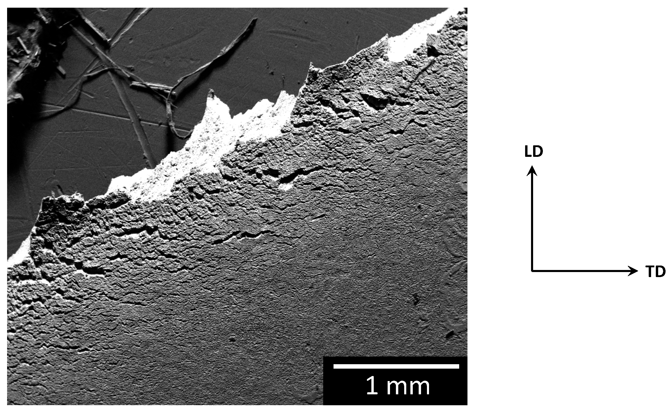
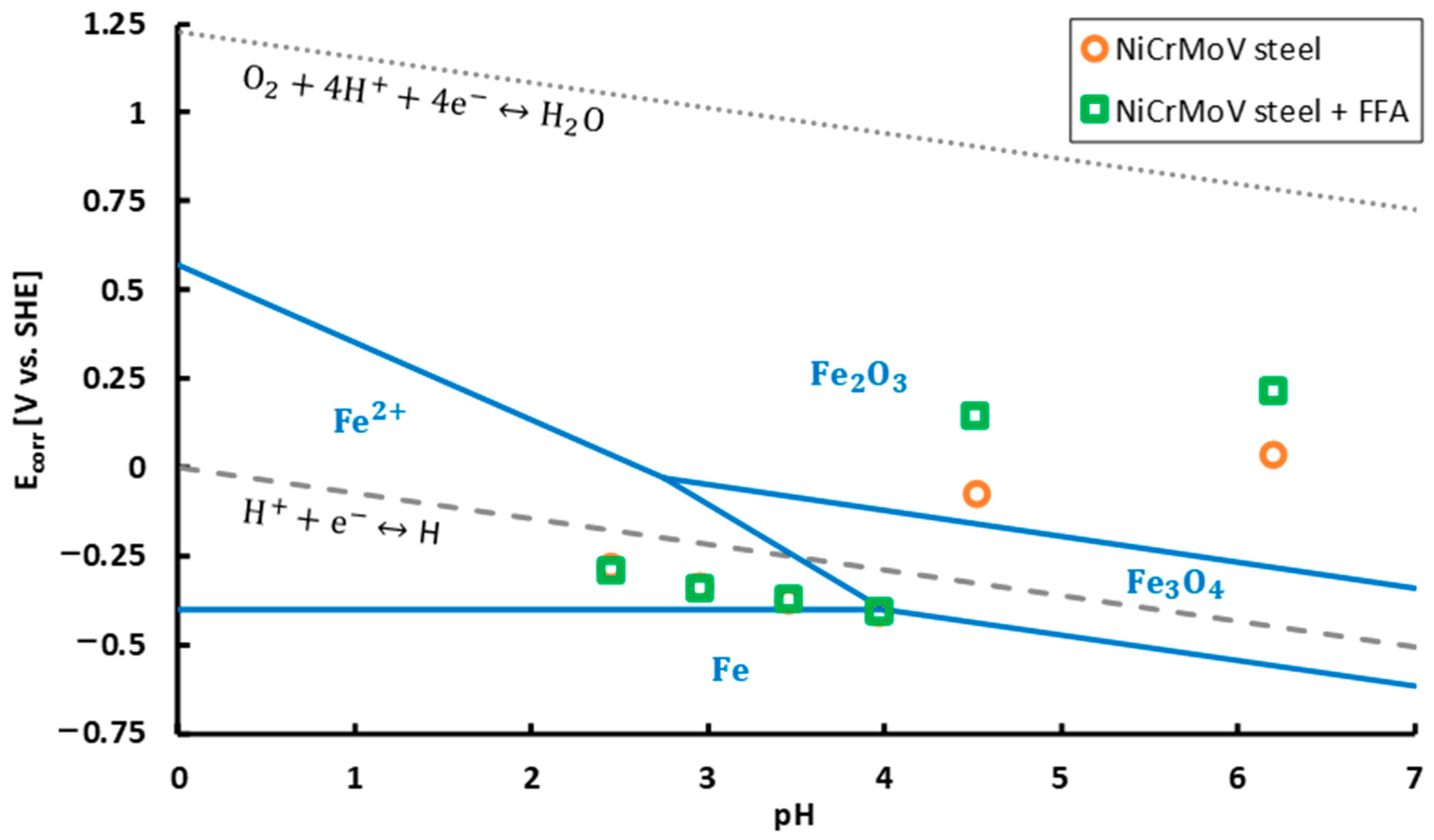
  • Based on potentiodynamic measurements, coating the steel with FFA had no significant influence on the thermodynamically stable iron states, neither on the type of active redox reactions, i.e., iron oxidation reaction, oxygen reduction reaction and hydrogen proton reduction reaction. Clearly, both coated and non-coated steel suffer from anodic dissolution and hydrogen embrittlement. In accordance, in addition to ductile dimples, embrittled regions on the fracture surface as well as stress-corrosion cracks on the top surface, which both are linked with hydrogen uptake and embrittlement, were observed both on the non-coated steel and the steel coated with FFA.
  • However, a ductility gain of 13% for FFA-coated steel with respect to non-coated steel when in situ CERT in 0.01 M acetic acid at 90 °C (pH = 3.5) was observed. This ductility gain was explained by the decrease in both corrosion rate and hydrogen uptake when covering the steel with an FFA layer. The FFA is hypothesised to disturb the accessibility of active sites for redox reactions to take place, as such lowering both anodic dissolution and hydrogen embrittlement.

Author Contributions

T.D.S.: investigation, methodology, formal analysis, writing—original draft, visualisation. E.L.: investigation, methodology, formal analysis, writing—review and editing. E.D.M.: Resources, writing—review and editing. W.H.: resources, writing—review and editing. N.D.G.: recourses, writing—review and editing. A.R.D.V.: writing—review and editing, funding acquisition. T.D.: methodology, formal analysis, writing—review and editing, supervision. K.V.: methodology, formal analysis, writing—review and editing, supervision, funding acquisition. All authors have read and agreed to the published version of the manuscript.

Funding

This work was supported by Ghent University and the IMPROVED project. The IMPROVED project is financed by the Interreg V Flanders—The Netherlands program, a program for transregional collaboration with financial support from the European Regional Development Fund. More info: www.grensregio.eu and www.improvedwater.eu. TD holds a postdoctoral fellowship of the Research Foundation—Flanders (FWO) via grant 12ZO420N. The authors also wish to thank the Special Research Fund (BOF), UGent (grant BOF15/BAS/062, grant BOF01P03516 and grant 24J069-17).

Acknowledgments

The authors wish to thank Saarschmiede for the supply of NiCrMoV steam turbine steel and Kurita for the supply of OLDA.

Conflicts of Interest

The authors declare no conflict of interest.

References

  1. Kluck, R.; Torres, J.; Antompietri, A.; Rivera, J. Experiences Using Neutralizing Amines to Control pH and Minimize FAC in a Combined-Cycle Power Plant. Power Plant Chem. 2010, 13, 94–103. [Google Scholar]
  2. Tsubakizaki, S.; Takada, M.; Suto, T.; Kawashima, H.; Ichihara, T.; Yoshida, A. Achievement on OT (Oxygenated Feed-Water Treatment) Application and Introduction of Countermeasures for Powdered Scale Deposit. Mitsubishi Heavy Ind. Tech. Rev. 2012, 49, 24–28. [Google Scholar]
  3. United States General Accounting Office. Nuclear Regulation: Action Needed to Ensure That Utilities Monitor and Repair Pipe Damage. GAO/RCED-88-73 Pipe Degradation; 1988. Available online: https://www.gao.gov/assets/150/146211.pdf (accessed on 20 April 2020).
  4. Buecker, B. Flow-Accelerated Corrosion: A Critical Issue Revisited. Power Eng. 2007, 111, 20–23. [Google Scholar]
  5. Buecker, B. The Evolution of Power Plant Water/Steam Chemistry. Power Eng. 2012, 116. Available online: https://www.power-eng.com/2012/10/01/the-evolution-power-plant-water-steam-chemistry/#gref (accessed on 19 July 2019).
  6. Dooley, R.B. Flow-Accelerated Corrosion in Fossil and Combined Cycle/HRSG Plants. Power Plant Chem. 2008, 10, 68–89. [Google Scholar]
  7. Uchida, S.; Naitoh, M.; Uehara, Y.; Okada, H.; Hiranuma, N.; Sugino, W.; Koshizuka, S.; Lister, D.H. Evaluation Methods for Corrosion Damage of Components in Cooling Systems of Nuclear Power Plants by Coupling Analysis of Corrosion and Flow Dynamics (III): Evaluation of Wall Thinning Rate with the Coupled Model of Static Electrochemical Analysis and Dynamic Double Oxide Layer Analysis. J. Nucl. Sci. Technol. 2009, 46, 31–40. [Google Scholar] [CrossRef]
  8. Uchida, S.; Naitoh, M.; Okada, H.; Uehara, Y.; Koshizuka, S. Evaluation of flow accelerated corrosion by coupled analysis of corrosion and flow dynamics. Relationship of oxide film thickness, hematite/magnetite ratio, ECP and wall thinning rate. Nucl. Eng. Des. 2011, 241, 4585–4593. [Google Scholar] [CrossRef]
  9. Jack, M.; Weerakul, S.; Lister, D.H. The Interaction of a Film-Forming Amine with Surfaces of a Recirculating Experimental Water Loop. In Proceedings of the International Conference on Heat Exchanger Fouling and Cleaning, Dublin, Ireland, 7–12 June 2015; pp. 112–118. [Google Scholar]
  10. Gasnier, C.; Lister, D.H. The Effects of Chemical Additives on Magnetite Deposition in Boiling Heat Transfer. In Proceedings of the International Conference on Heat Exchanger Fouling and Cleaning, Budapest, Hungary, 9–14 June 2013; pp. 85–93. [Google Scholar]
  11. Gasnier, C. The Effect of Chemical Additives on the Deposition of Magnetite onto Alloy-800 under Nucleate Boiling Heat Transfer, Master of Science in Engineering. Master’s Thesis, The University of New Brunswick, Fredericton, NB, Canada, 2014. [Google Scholar]
  12. Phosphate and NaOH Treatments for the Steam-Water Circuits of Drum Boilers of Fossil and Combined Cycle/HRSG Power Plants; International Association for the Properties of Water and Steam: Stockholm, Sweden, 2015.
  13. Baghni, I.M.; Zwebek, A.I. Using of congruent phosphate as equilibrium phosphate boilers water treatment. In Disaster Management and Human Health Risk: Reducing Risk, Improving Outcomes; WIT Press: Southampton, UK, 2009; pp. 159–169. [Google Scholar] [CrossRef] [Green Version]
  14. Selby, A. Caustic Treatment of Electric Utility Drum Boilers. Mater. Perform. 2009, 48, 39–43. [Google Scholar]
  15. Dooley, R.B.; Bursik, A. Caustic Gouging. Power Plant Chem. 2010, 12, 188–192. [Google Scholar]
  16. Nalco Chemical Company. Phosphate Hideout. 1996. Available online: https://www.steamforum.com/pictures/B-268.pdf (accessed on 15 July 2019).
  17. Dooley, R.B.; Bursik, A. Acid Phosphate Corrosion. Power Plant Chem. 2010, 12, 368–372. [Google Scholar]
  18. Cooper, J.R.; Dooley, R.B. Procedures for the Measurement of Carryover of Boiler Water into Steam; International Association for the Properties of Water and Steam: Berlin, Germany, 2008. [Google Scholar]
  19. Jonas, O.; Machemer, L. Steam Turbine Corrosion and Deposits Problems and Solutions. In Proceedings of the 37th Turbomachinery Symposium, Houston, TX, USA, 8–11 September 2008; pp. 211–228. [Google Scholar]
  20. Hater, W.; Smith, B.; McCann, P.; de Bache, A. Experience with the Application of a Film Forming Amine in the Connah’s Quay Triple Stage Combined Cycle Gas Turbine Power Plant Operating in Cycling Mode. Power Plant Chem. 2018, 20, 136–144. [Google Scholar]
  21. Asano, T.; Levine, A.D. Wastewater reclamation, recycling and reuse: Past, present, and future. Water Sci. Technol. 1996, 33, 1–14. [Google Scholar] [CrossRef]
  22. Ma, H.; Allen, H.E.; Yin, Y. Characterization of isolated fractions of dissolved organic matter from natural waters and a wastewater effluent. Water Res. 2001, 35, 985–996. [Google Scholar] [CrossRef]
  23. Anderson, J. The environmental benefits of water recycling and reuse. Water Supply 2003, 3, 1–10. [Google Scholar] [CrossRef] [Green Version]
  24. Van Lipzig, N.; Willems, P. Actualisatie en Verfijning Klimaatscenario’s Tot 2100 voor Vlaanderen; MIRA: Mechelen, Belgium, 2015. [Google Scholar]
  25. Unesco. Wastewater: The Untapped Resource; UNESCO: Paris, France, 2017. [Google Scholar]
  26. Parker, J.G.; Sadler, M. Stress corrosion cracking of a low alloy steel in high purity steam. Corros. Sci. 1975, 15, 57–63. [Google Scholar] [CrossRef]
  27. McMinn, A.; Lyle, F.F.; Leverant, G.R. Mechanical and metallurgical properties of retired 3.5NiCrMoV low pressure steam turbine discs. J. Mater. Energy Syst. 1984, 6, 184–199. [Google Scholar] [CrossRef]
  28. Lyle, F.F.; McMinn, A.; Leverant, G.R. Low-Pressure Steam Turbine Disc Cracking—An Update. Proc. Inst. Mech. Eng. Part A Power Process. Eng. 1985, 199, 59–67. [Google Scholar] [CrossRef]
  29. Liu, C.; Macdonald, D.D. Prediction of Failures of Low-Pressure Steam Turbine Disks. J. Press. Vessel. Technol. 1997, 119, 393–400. [Google Scholar] [CrossRef]
  30. McCloskey, T.H. Troubleshooting Turbine Steam Path Damage Mechanisms. In Turbomachinery Laboratories; Texas A&M University: College Station, TX, USA, 2002; pp. 105–144. [Google Scholar] [CrossRef]
  31. Dooley, R.B.; Bursik, A. Proceedings of the International Conference on the Interaction of Organics and Organic Cycle Treatment Chemicals with Water, Steam and Materials; Stuttgart, Germany, 4–6 October 2005; Electric Power Research Institute: Palo Alto, CA, USA, 2005. [Google Scholar]
  32. Savelkoul, J.; van Lier, R. Operational Experience with Organics in Industrial Steam Generation. Power Plant Chem. 2005, 7, 733–739. [Google Scholar]
  33. Zhou, S.; Turnbull, A. Steam Turbine Operating Conditions, Chemistry of Condensates, and Environment Assisted Cracking—A Critical Review; NPL Report MATC (A). 95; National Physical Laboratory: Teddington, Middlesex, UK, 2002. [Google Scholar]
  34. Huijbregts, W.M.M.; Leferink, R.G.I. Latest advances in the understanding of acid dewpoint corrosion: Corrosion and stress corrosion cracking in combustion gas condensates. Anti-Corros. Methods Mater. 2004, 51, 173–188. [Google Scholar] [CrossRef] [Green Version]
  35. Technical Guidance Document: Steam Purity for Turbine Operation; International Association for the Properties of Water and Steam: London, UK, 2013.
  36. Svoboda, R.; Gabrielli, F.; Hehs, H.; Seipp, H.-G.; Leidich, F.-U.; Roberts, B. Organic Impurities and Organic Conditioning Agents in the Steam/Water Cycle: A Power Plant Manufacturer’s Point of View. Power Plant Chem. 2006, 8, 502–509. [Google Scholar]
  37. Palmer, D.A.; Marshall, S.L.; Simonson, J.M.; Gruszkiewicz, M.S. The Partitioning of Acetic, Formic, and Phosphoric Acids between Liquid Water and Steam; Oak Ridge National Laboratory: Oak Ridge, TN, USA, 2008. [Google Scholar]
  38. Moed, D.H.; Verliefde, A.; Heijman, S.G.; Rietveld, L.C. Organic acid formation in steam–water cycles: Influence of temperature, retention time, heating rate and O2. Appl. Therm. Eng. 2014, 65, 194–200. [Google Scholar] [CrossRef]
  39. Moed, D.H.; Verliefde, A.R.D.; Rietveld, L.C. Effects of Temperature and Pressure on the Thermolysis of Morpholine, Ethanolamine, Cyclohexylamine, Dimethylamine, and 3-Methoxypropylamine in Superheated Steam. Ind. Eng. Chem. Res. 2015, 54, 2606–2612. [Google Scholar] [CrossRef]
  40. De Meyer, E.; Peeters, B.; Vanoppen, M.; Verbeken, K.; Verliefde, A.R.D. Organic Matter Composition More Important than Concentration in Ion Exchange Demineralization of Different Water Qualities for the Production of Steam. Ind. Eng. Chem. Res. 2018, 57, 3742–3752. [Google Scholar] [CrossRef]
  41. De Meyer, E.; Van Overstraeten, T.; Heyse, J.; Uddin, M.R.; Vanoppen, M.; Boon, N.; De Gusseme, B.; Verbeken, K.; Verliefde, A.R.D. Organic Matter and Microbial Cell Density Behavior during Ion Exchange Demineralization of Surface Water for Boiler Feedwater. Ind. Eng. Chem. Res. 2019, 58, 14368–14379. [Google Scholar] [CrossRef]
  42. Betova, I.; Bojinov, M.; Saario, T. Film-Forming Amines in Steam/Water Cycles—Structure, Properties, and Influence on Corrosion and Deposition Processes; VTT Technical Research Centre of Finland: Espoo, Finland, 2014. [Google Scholar]
  43. Pensini, E.; Van Lier, R.; Cuoq, F.; Hater, W.; Halthur, T. Enhanced corrosion resistance of metal surfaces by film forming amines: A comparative study between cyclohexanamine and 2-(diethylamino)ethanolbased formulations. Water Resour. Ind. 2018, 20, 93–106. [Google Scholar] [CrossRef]
  44. Van Lier, R.; Cuoq, F.; Peters, R.; Savelkoul, J. Ten Years of Experience with Polyamines in the High-Pressure Steam System of a Naphta Cracker. Power Plant Chem. 2015, 17, 356–363. [Google Scholar]
  45. Hater, W.; Olivet, D. The chemistry and properties of organic boiler feed water additives based on film-forming amines, and their use in steam generators. In Proceedings of the ICPWS XV, Berlin, Germany, 7–11 September 2008; p. 9. [Google Scholar]
  46. Stiller, K.; Wittig, T.; Urschey, M. The Analysis of Film-Forming Amines—Methods, Possibilities, Limits and Recommendations. Power Plant Chem. 2011, 13, 602–611. [Google Scholar]
  47. Odar, S. Use of Film Forming Amines (FFA) in Nuclear Power Plants for Lay-Up and Power Operation; Advanced Nuclear Technology International: Molnlycke, Sweden, 2017. [Google Scholar]
  48. Smith, B.; McCann, P.; Uchida, K.; Mori, S.; Jasper, J.; Hater, W. Determination of Oleyl Propylenediamine, a Commonly Used Film Forming Amine, on the Surfaces of Water-Steam Cycles. Power Plant Chem. 2017, 19, 129–140. [Google Scholar]
  49. Riznic, J. Steam Generators for Nuclear Power Plants; Woodhead Publishing: Sawston, UK, 2017. [Google Scholar]
  50. Technical Guidance Document: Application of Film Forming Substances in Fossil and Combined Cycle Plants; International Association for the Properties of Water and Steam: Banff, AB, Canada, 2019.
  51. Steam Chemistry: Interaction of Chemical Species with Water, Steam, and Materials during Evaporation, Superheating, and Condensation; Electric Power Research Institute: Freiburg, Germany, 1999.
  52. Tomarov, G.V.; Mikhailov, A.V.; Velichko, E.V.; Budanov, V.A. Extending the erosion-corrosion service life of the tube system of heat-recovery boilers used as part of combined-cycle plants. Therm. Eng. 2010, 57, 22–27. [Google Scholar] [CrossRef]
  53. Bursik, A.; Hater, W. All-Volatile Treatment with Film Forming Amines—A First Suggestion for an Application Guidance. Power Plant Chem. 2015, 17, 342–353. [Google Scholar]
  54. International Association for the Properties of Water and Steam. Technical Guidance Document: Application of Film Forming Amines in Fossil and Combined Cycle Plants; International Association for the Properties of Water and Steam: Dresden, Germany, 2016. [Google Scholar]
  55. Dooley, B.; Lister, D. Flow-Accelerated Corrosion in Steam Generating Plants. Power Plant Chem. 2018, 20, 194–242. [Google Scholar]
  56. Lister, D. Flow-accelerated corrosion in power plants: The influence of corrosion-product oxides. In Proceedings of the EUROCORR 2019 The Annual Congress of the European Federation of Corrosion, Seville, Spain, 9–13 September 2019; p. 20. [Google Scholar]
  57. Weerakul, S.; Leaukosol, N.; Lister, D.H.; Mori, S.; Hater, W. Effects on Flow-Accelerated Corrosion of Oleylpropanediamine Under Single-Phase Water Conditions Pertinent to Power Plant Feedwater. Corrosion 2020, 76, 217–230. [Google Scholar] [CrossRef]
  58. Foret, C.; Stoianovici, G.; Chaussec, G.; de Bache, A.; Kolk, C.Z.; Hater, W. Study of Efficiency and Stability of Film Forming Amines (FFA) for the Corrosion Protection of the Carbon Steel in Water Circuits. In Proceedings of the Edinburgh International Conference Centre, Edinburgh, UK, 7–11 September 2008; p. 12. [Google Scholar]
  59. De Meyer, E.; De Seranno, T.; Hater, W.; Vanoppen, M.; Verbeken, K.; Verliefde, A.R.D. Degradation of oleyl-propylenediamine under steam generator conditions. 2020. submitted. [Google Scholar]
  60. De Seranno, T.; Lambrechts, E.; Depover, T.; Verliefde, A.R.D.; Verbeken, K. SCC of steam turbine steel in acidic aqueous environment. In Proceedings of the EUROCORR 2019 The Annual Congres of the European Federation of Corrosion, Seville, Spain, 9–13 September 2019; p. 10. [Google Scholar]
  61. De Seranno, T.; Lambrechts, E.; Verliefde, A.; DePover, T.; Verbeken, K. Mechanistic interpretation on acidic stress-corrosion cracking of NiCrMoV steam turbine steel. Mater. Sci. Eng. A 2020, 140433. [Google Scholar] [CrossRef]
  62. Bezzoli, P.; Cramer, K. Organic Plant Cycle Treatment Chemicals—A Power Plant Chemistry Interview. Power Plant Chem. 2009, 11, 45–47. [Google Scholar]
  63. De Meyer, E. The Behavior of Organic Matter in Industrial Demineralization and Steam-Water Cycles. Ph.D. Thesis, Ghent University, Ghent, Belgium, 2020. [Google Scholar]
  64. Gras, J.M.; Vaillant, F.; Dordonat, M.; Dury, J.P. Stress Corrosion Cracking of Turbine Disc Steels: A Study of Mechanism; Electricité de France: Direction Des Etudes et Recherches; Service Réacteurs Nucléaires et Echangeurs: Département Etude Des Matériaux, 1993; Available online: https://inis.iaea.org/collection/NCLCollectionStore/_Public/27/000/27000428.pdf?r=1 (accessed on 21 November 2019).
  65. Ghobeira, R.; Philips, C.; Liefooghe, L.; Verdonck, M.; Asadian, M.; Cools, P.; Declercq, H.; De Vos, W.H.; De Geyter, N.; Morent, R. Synergetic effect of electrospun PCL fiber size, orientation and plasma-modified surface chemistry on stem cell behavior. Appl. Surf. Sci. 2019, 485, 204–221. [Google Scholar] [CrossRef]
  66. De Wispelaere, M. Early Condensate in a Fossil Power Plant using organic treatment. In Proceedings of the 14th International Conference on the Properties of Water and Steam, Kyoto, Japan, 29 August–3 September 2004; pp. 602–605. [Google Scholar]
  67. Iannuzzi, M. Environmentally assisted cracking (EAC) in oil and gas production. In Stress Corrosion Cracking; Elsevier: Amsterdam, The Netherlands, 2011; pp. 570–607. [Google Scholar] [CrossRef]
  68. De Seranno, T.; Vandewalle, L.; DePover, T.; Verliefde, A.R.; Verbeken, K. Mechanical degradation of Fe-C-X steels by acidic stress-corrosion cracking. Corros. Sci. 2020, 167, 108509. [Google Scholar] [CrossRef]
  69. De Seranno, T.; DePover, T.; Verliefde, A.R.; Verbeken, K. Evaluation of the active mechanism for acidic SCC induced mechanical degradation: A methodological approach. Mater. Sci. Eng. A 2020, 790, 139645. [Google Scholar] [CrossRef]
  70. DePover, T.; Escobar, D.M.P.; Wallaert, E.; Zermout, Z.; Verbeken, K. Effect of hydrogen charging on the mechanical properties of advanced high strength steels. Int. J. Hydrogen Energy 2014, 39, 4647–4656. [Google Scholar] [CrossRef]
  71. Baux, J.; Caussé, N.; Esvan, J.; Delaunay, S.; Tireau, J.; Roy, M.; You, D.; Pébère, N. Impedance analysis of film-forming amines for the corrosion protection of a carbon steel. Electrochim. Acta 2018, 283, 699–707. [Google Scholar] [CrossRef] [Green Version]
  72. Weinhold, F.; Klein, R.A. What is a hydrogen bond? Resonance covalency in the supramolecular domain. Chem. Educ. Res. Pract. 2014, 15, 276–285. [Google Scholar] [CrossRef]
  73. Vinutha, M.R.; Venkatesha, T.V. Review on Mechanistic Action of Inhibitors on Steel Corrosion in Acidic Media. Port. Electrochim. Acta 2016, 34, 157–184. [Google Scholar] [CrossRef]
  74. Jäppinen, E.; Ikäläinen, T.; Järvimäki, S.; Saario, T.; Sipilä, K.; Bojinov, M. Corrosion Behavior of Carbon Steel Coated with Octadecylamine in the Secondary Circuit of a Pressurized Water Reactor. J. Mater. Eng. Perform. 2017, 26, 6037–6046. [Google Scholar] [CrossRef]
  75. Cools, P.; De Geyter, N.; Vanderleyden, E.; Dubruel, P.; Morent, R. Surface Analysis of Titanium Cleaning and Activation Processes: Non-thermal Plasma Versus Other Techniques. Plasma Chem. Plasma Process. 2014, 34, 917–932. [Google Scholar] [CrossRef]
  76. Topp, H. On the Interaction of Chemically Conditioned Water with Steel Heating Surfaces during Saturated Pool Boiling—An Experimental Thermotechnical Approach. Ph.D. Thesis, University of Rostock, Rostock, Germany, 2010. [Google Scholar]
  77. Haynes, W.M. CRC Handbook of Chemistry and Physics, 97th ed.; CRC Press: Boca Raton, FL, USA, 2016. [Google Scholar]
  78. Van Gorp, A.C. Influence of Heat Treatment on the Fracture Toughness of AA6061 and AA6061 mmc. Master’s Thesis, Delft University of Technology, Delft, The Netherlands, 1999. [Google Scholar]
  79. Beachem, C.; Meyn, A. Fracture by microscopic plastic deformation processes. In Electron Fractography; Beachem, C., Ed.; ASTM International: Conshohocken, PA, USA, 1968; pp. 59–88. [Google Scholar]
  80. Atrens, A.; Venezuela, J.; Liu, Q.; Zhou, Q.; Verbeken, K.; Tapia-Bastidas, C.; Gray, E.; Christien, F.; Wolski, K. Electrochemical and Mechanical Aspects of Hydrogen Embrittlement Evaluation of Martensitic Steels. In Reference Module in Chemistry, Molecular Sciences and Chemical Engineering; Elsevier: Amsterdam, The Netherlands, 2017; pp. 201–225. [Google Scholar] [CrossRef]
  81. Pourbaix, M. Atlas of Electrochemical Equilibria in Aqueous Solutions. 1974. Available online: https://linkinghub.elsevier.com/retrieve/pii/0022072867800597 (accessed on 6 January 2020).
  82. Jones, R.H. Stress-Corrosion Cracking; ASM International: Materials Park, OH, USA, 1992. [Google Scholar]
  83. Was, G.S. Fundamentals of Radiation Materials Science: Metals and Alloys; Springer: Berlin, Germany; New York, NY, USA, 2007. [Google Scholar]
  84. Lynch, S.P. Mechanistic and fractographic aspects of stress-corrosion cracking (SCC). In Stress Corrosion Cracking: Theory and Practice; Woodhead Publishing: Sawston, UK, 2011; pp. 3–89. [Google Scholar] [CrossRef]
  85. Cheng, Y.F. Fundamentals of Stress Corrosion Cracking. In Stress Corrosion Cracking of Pipelines; John Wiley & Sons, Inc.: Hoboken, NJ, USA, 2013; pp. 7–41. [Google Scholar] [CrossRef]
  86. Newman, J.; Thomas-Alyea, K.E. Electrochemical Systems, 3rd ed.; John Wiley & Sons, Inc.: Hoboken, NJ, USA, 2004. [Google Scholar]
  87. Alonso-Vante, N.; Roldán, C.A.C.; de Guadalupe González Huerta, R.; Sánchez, G.R.; Robledo, A.M. Fundamentals of Electrocatalyst Materials and Interfacial Characterization: Energy Producing Devices and Environmental Protection; John Wiley & Sons, Inc.: Hoboken, NJ, USA, 2019. [Google Scholar] [CrossRef]
  88. Santos, E.; Hindelang, P.; Quaino, P.; Schmickler, W. A model for the Heyrovsky reaction as the second step in hydrogen evolution. Phys. Chem. Chem. Phys. 2011, 13, 6992–7000. [Google Scholar] [CrossRef]
  89. Djukic, M.; Zeravcic, V.S.; Bakic, G.; Sedmak, A.; Rajicic, B. Hydrogen damage of steels: A case study and hydrogen embrittlement model. Eng. Fail. Anal. 2015, 58, 485–498. [Google Scholar] [CrossRef]
  90. Shinagawa, T.; Garcia-Esparza, A.T.; Takanabe, K. Insight on Tafel slopes from a microkinetic analysis of aqueous electrocatalysis for energy conversion. Sci. Rep. 2015, 5, 13801. [Google Scholar] [CrossRef] [Green Version]
  91. De Seranno, T.; Vander Vennet, S.; Claeys, L.; Verliefde, A.R.D.; Depover, T.; Verbeken, K. Experimental confirmation of the role of hydrogen in acidic stress-corrosion cracking of low carbon steel. 2020. submitted. [Google Scholar]
  92. Bäßler, R.; Uhlemann, M.; Mummert, K. Inhibiting effect of octadecylamine on pitting corrosion behaviour of stainless steel type 1.4541 up to 250 °C. Mater. Corros. 1999, 50, 146–153. [Google Scholar] [CrossRef]
Figure 1. Representative images of the microstructure of 27NiCrMoV15-6 steam turbine steel (a) light optical microscopy (LOM) image, (b) scanning electron microscopy (SEM) image.
Metals 10 01628 g001
Figure 2. Structural formula of oleyl propylene diamine (OLDA).
Metals 10 01628 g002
Figure 3. Schematic representation of the coating set-up.
Metals 10 01628 g003
Figure 4. Tensile specimen geometry (mm) (thickness = 1.5 mm, TD = transverse direction, LD = loading direction) [61]. Adapted from [61], with permission from Elsevier, 2020.
Metals 10 01628 g004
Figure 5. Static sessile drop technique images and contact angles θ (a) no film-forming amines (FFA) coating, (b) FFA coating: 5 ppm, 1 day, 60 °C, (c) FFA coating: 5 ppm, 1 day, 90 °C. Influence of FFA coating application temperature on hydrophobicity of NiCrMoV steel.
Metals 10 01628 g005
Figure 6. X-ray photoelectron spectroscopy (XPS) overview scan spectra of non-coated and FFA-coated NiCrMoV steam turbine steel.
Metals 10 01628 g006
Figure 7. Influence of FFA coating on mechanical properties of NiCrMoV steel in 0.01 M acetic acid at 90 °C ( ε . = 10 6   s 1 ) .
Metals 10 01628 g007
Figure 8. Representative secondary electron images of the fracture surface for non-coated NiCrMoV steel tested in 0.01 M acetic acid at 90 °C (a) ductile dimples with serpentine glide [61], Adapted from [61], with permission from Elsevier, 2020. (b) more embrittled regions, (c) stress-corrosion crack.
Metals 10 01628 g008
Figure 9. Representative secondary electron images of the top surface for non-coated NiCrMoV steel tested in 0.01 M acetic acid at 90 °C (a) corrosion damage on the entire surface is visible with more damage close to the main crack, (b) detail of the small cracks close to the main crack [61]. Adapted from [61], with permission from Elsevier, 2020.
Metals 10 01628 g009
Figure 10. Representative secondary electron images of the fracture surface for FFA-coated NiCrMoV steel tested in 0.01 M acetic acid at 90 °C (a) ductile dimples, (b) more embrittled fracture surface showing stress-corrosion cracking at the edge of the sample.
Metals 10 01628 g010
Figure 11. Representative secondary electron image of the top surface for FFA-coated NiCrMoV steel tested in 0.01 M acetic acid at 90 °C.
Metals 10 01628 g011
Figure 12. Overview secondary electron images of the fracture surface of NiCrMoV steel tested in 0.01 M acetic acid at 90 °C (a) without coating, (b) with FFA coating.
Metals 10 01628 g012
Figure 13. Representative polarisation curves of non-coated and FFA-coated NiCrMoV steam turbine steel in different concentrations of acetic acid at 90 °C.
Metals 10 01628 g013
Figure 14. Influence of FFA coating on corrosion potential (Ecorr) of NiCrMoV steam turbine steel at 90 °C. Dotted line represents the oxygen reduction reaction line, dashed line represents the hydrogen proton reduction reaction line. Thermodynamically stable forms of iron (molality of 1) are represented in blue. Diagram based on thermodynamic data from FactSage©.
Metals 10 01628 g014
Figure 15. Influence of FFA coating on corrosion rate (µm/year) of NiCrMoV steel at 90 °C for different hydrogen proton concentrations (mM).
Metals 10 01628 g015
Table 1. Chemical composition of the used steam turbine steel in wt.%.
CNiCrMoVFe
0.273.701.500.350.10Balance
Table 2. Surface atomic composition of non-coated and FFA-coated NiCrMoV steam turbine steel in at.%.
FeCNONiCrMoV
non-coated15.930.90.551.80.40.40.1Trace element
FFA coated3.171.53.621.40.20.10.1Trace element
Table 3. Representative electrochemical data. Material: NiCrMoV steel. FFA coating, environment, corrosion potential E corr and corrosion current density j corr . Temperature = 90 °C.
FFA CoatingEnvironment E c o r r   ( V   vs .   SHE ) j c o r r   ( µ A / cm 2 )
nodemi water0.0400.4
no10−4 M acetic acid−0.0562.0
no10−3 M acetic acid−0.4055.2
no10−2 M acetic acid−0.37413.9
no10−1 M acetic acid−0.34244.3
no1 M acetic acid−0.299135.7
yesdemi water0.2140.3
yes10−4 M acetic acid0.1471.6
yes10−3 M acetic acid−0.4054.4
yes10−2 M acetic acid−0.37212.9
yes10−1 M acetic acid−0.33932.0
yes1 M acetic acid−0.291113.0
Publisher’s Note: MDPI stays neutral with regard to jurisdictional claims in published maps and institutional affiliations.

