1. Introduction
Looking at today’s society, it can be observed that the demand and desire of greenhouse gas saving and sustainable technologies is higher than ever before. As a result of this social rethinking, numerous branches of industry are being affected, including the automotive industry. This has led to a rapid change in drive technology from the combustion to electric engine [
1,
2,
3]. One of the core technologies for the implementation of the electric engine, which has already established itself in the small electronics sector (smartphones, laptops, etc.), are lithium batteries [
2,
4]. In this context, sales of one million electric vehicles per year were already recorded worldwide in 2017, which represents an increase of 56% compared to the previous year, 2016 [
5,
6].
Since the 1990s, the lithium-ion battery (LIB) has been the most common form of lithium battery technology. However, despite the constant development and different forms (NMC, NCA, LMO, LFP, etc.), the most modern LIBs reach a physical limit at a specific gravimetric energy density of 350–400 Wh/kg [
6,
7,
8]. Furthermore, critical raw materials such as graphite (C) or cobalt (Co), but also strategic raw materials such as lithium (Li) or nickel (Ni) are required for the production of these batteries [
4,
6,
9,
10]. Not only the incidence of the mentioned raw materials, but also the location of the mining areas and the associated import dependency are major challenges for European countries. Furthermore, the socially critical aspects of some raw materials should be considered (e.g., cobalt) [
4,
6].
Promising alternative future technologies to LIBs are lithium–air (L–A) batteries and lithium–sulfur batteries (LSBs). Both systems are currently in the development phase and will probably eliminate many of the disadvantages of LIBs [
7,
11]. Although the basic structure (electrodes, liquid electrolyte, etc.) of LSBs is similar to that of LIB, the two systems are fundamentally different in cell chemistry. The LSB has a pure lithium metal anode and a sulfur–carbon composite cathode. Carbon is indispensable, since sulfur is electrically non-conductive. The sulfur content within the cathode can vary between 50 and 70 wt.%. The remaining proportion is accounted for carbon and small quantities of the binder. In general, lithium bis(trifluoromethanesulfonyl)imide (LiN(SO
2CF
3)
2, LiTFSI) is used as the conducting salt [
7]. The actual cell reaction takes place through the complex formation of several polysulfides (from S
8 over Li
2S
4 up to Li
2S). Therefore, an LSB is exactly a lithium polysulfide battery [
8].
Due to the materials used, an LSB can theoretically achieve a specific energy density of 600 Wh/kg. On a cell level, 460 Wh/kg have already been reached [
12]. A further advantage besides the high energy density is the use of toxicologically harmless, inexpensive, and readily available sulfur as an active material [
7,
8,
13]. However, despite the numerous advantages of LSBs compared to LIBs, the cycle stability of LSBs currently represents a major challenge. The shuttle mechanism (a shuttle mechanism or effect is the cycle in which the cathodically dissolved polysulfides [S
2]
2− diffuse unwantedly to the lithium anode, where they are reduced to lower polysulfides [S
n-x]
2− and migrate back again. As a result, a part of the cathode reaction takes place at the anode, and the cell is continuously discharging [
8]) leads to a continuous self-discharge of the cell. Due to these problems, LSBs currently achieve only a few hundred charging cycles [
13,
14,
15].
In [
7,
16], a detailed elaboration on the chemical structure and redox reactions in Lithium-Sulfur Batteries is given. During charging the Li-ions diffuse from the carbon-sulfur cathode to the lithium anode and vice versa during discharging from the lithium anode to the carbon-sulfur cathode [
7,
16]. Here, the different polysulfides are related to the state of charge (SOH), namely for charging the sequence of polysulfide formation will be S
8, Li
2S
8, Li
2S
6, Li
2S
4, Li
2S
3, Li
2S
2 and finally Li
2S [
16]. So, depending on the SOH the shares of Li
2S
8 and Li
2S can be different, showing also different properties in terms of solubility, e.g. in the electrolyte [
16].
Regardless of which lithium battery technology will finally prevail, a spent lithium battery represents a versatile and important secondary raw material source. Based on the import dependency of almost all materials required for battery production, the importance of recycling is underlined once again. In this context, the recycling process must be highly efficient, environmentally compatible, and economical [
6].
In the case of LIBs, there are already some proven recycling process routes that use a combination of mechanical, pyro- and/or hydrometallurgical processes [
1]. Since LSBs are a new, innovative battery system, there are no significant approaches for a recycling process so far. However, EU-funded projects, such as HELIS (High Energy Lithium Sulphur cells and batteries) [
17] or LISA (Lithium sulphur for SAfe road electrification) [
18] aim to combine battery development and circular economy approaches, but no outcome regarding a recycling path has been published until now. In addition, there are already approaches to improve the design for recycling by using recyclable components, such as a Co
3Mo
3C-separator [
19]. This paper presents for the first time a recycling concept for the lithium–sulfur battery with the aim of recovering all elements, considering the legal requirement of 50 wt.%. This legal frame is demanded in the EU battery directives 2006/66/EG [
20] and 493/2012 [
21], where the threshold of 50 wt.% is described as recycling efficiency (RE) of at least 50 wt.% based on a battery’s cell level, as can be seen in Formula (1) [
21]:
To reach this target, a suitable recycling path has to be developed for any battery system. Since LSBs do have a metallic lithium anode, which is critical in terms of a high reactivity leading to exothermal oxidation and, hence, safety issues [
22,
23], a suitable pre-treatment before entering the metallurgical processing can be helpful. It is also crucial to work in an inert atmosphere to prevent atmosphere-related oxidation [
24]. In addition, metallic lithium can ignite when heated beyond 180 °C in air [
25], which can even occur due to mechanical strain, such as shredding [
26], or when being in contact with moisture [
27]. One form of thermal pre-treatments is a pyrolysis, where the cells are deactivated in the absence of oxygen at temperatures of maximum 600 °C [
28]. In order to remove the containing organics, such as binders, an optimal temperature of 550 °C in air has been defined by Chen et al., using LCO cells [
29]. Both pyrolysis and incineration, with some oxygen shares, are thermal pre-treatments for a safe cell deactivating and facilitating of further downstream recycling without an uncontrolled thermal runaway [
30,
31]. Another benefit comprises an eased detachment of substrate foils and active mass [
32], and especially for hydrometallurgical processing, a thermal pre-treatment is suggested [
33]. For a metallurgical recycling, both hydro- and pyrometallurgical processes are available [
34]. Pyrometallurgy is established regarding the production of Co, Ni, and Cu alloys, hence, rather ignoble and valuable component recycling [
35], whereas hydrometallurgy is also able to selectively separate rather ignoble components, such as graphite, aluminum, or lithium [
35,
36,
37]. This is why this study considers hydrometallurgical treatments as suitable for the purpose of a circular economy approach. Although hydrometallurgy comprises generally slower kinetics [
37], it leads to higher yields and lower energy consumption [
36].
Based on LIBs, different strategies for optimal wet-chemical processing are investigated around the world. Within this variety of approaches, an overview on relevant literature is given as follows. Generally, besides physical separation methods in aqueous environments, such as flotation [
38], chemical processing is mainly based on leaching, precipitation, solvent extraction, and ion exchanging [
39]. Within acidic leaching, both organic or inorganic solvents can be used. For LIBs recycling approaches, studies have examined hydrochloric acid (HCl), sulfuric acid (H
2SO
4), phosphoric acid (H
3PO
4), and nitric acid (HNO
3) in terms of inorganic acids, and citric acid, malic acid, acetic acid, lactic acid, or trichloroacetic acid have been studied in terms of organic acids. For every solvent, different concentrations, leaching temperatures, or solid/liquid ratios have been reported [
40]. Within these solvents, Zou et al. report a lithium leaching efficiency of 100% using 4-molar H
2SO
4 and adding of 30 wt.% H
2O
2, and a lithium yield of 80% recovered as lithium carbonate by using sodium carbonate (Na
2CO
3) [
41]. A similar approach is presented by Wang et al. [
42,
43]. In this context, 2 molar H
2SO
4 and 4 molar HCl with or without addition of 50 g/L H
2O
2 were examined, leading to a lithium yield of maximum 64% when using H
2SO
4. Castillo et al. investigated 0.5 to 5-molar HNO
3, adjusted the pH value by NaOH, and obtained 100% leaching efficiency for lithium, when applying acidic concentrations between 1 and 2 moles [
44]. Besides acidic leaching, alkaline leaching can also be applied, which is rarely investigated for LIBs [
45]. Ferreira et al. have followed an approach starting with alkaline leaching in NaOH, since aluminum shows a better recyclability in basic environment, and then, the pH value was adjusted step-wise by using H
2SO
4 and H
2O
2. This set-up leads to a leaching efficiency of 100% for lithium [
46]. The approach for the novel and innovative recycling process for lithium–sulfur batteries is based on the knowledge and experience gained from the hydrometallurgical recycling processes of lithium-ion batteries. Elements such as Co, Ni, or Cu are no longer inserted into an LSB, so the process scheme is adjusted. However, during charging and discharging, many different, intermediate polysulfides with Li and S are formed, making the recycling process challenging [
47]. This study’s target is a zero-waste recovery of the components C, S, Li, and Al.
Research Needs and Work Hypothesis
Since Li–S batteries are a promising alternative to conventional Li-ion batteries, investigating their recycling process options is crucial regarding the concepts of circular economy and waste minimization. The intrinsic materials’ value of Li–S batteries is comparatively lower due to the dispensing of cobalt and nickel, while this work focuses on the recovery of lithium. Other material fractions, such as carbon and aluminum, will be separated, too, but no discussion on recovery yields is taking place at this early-stage of recycling considerations for Li–S batteries. The lithium contents in Li–S batteries are higher than in conventional Li-ion batteries, while lithium has a higher impact on the recycling efficiency than in Li-ion batteries.
2. Materials and Methods
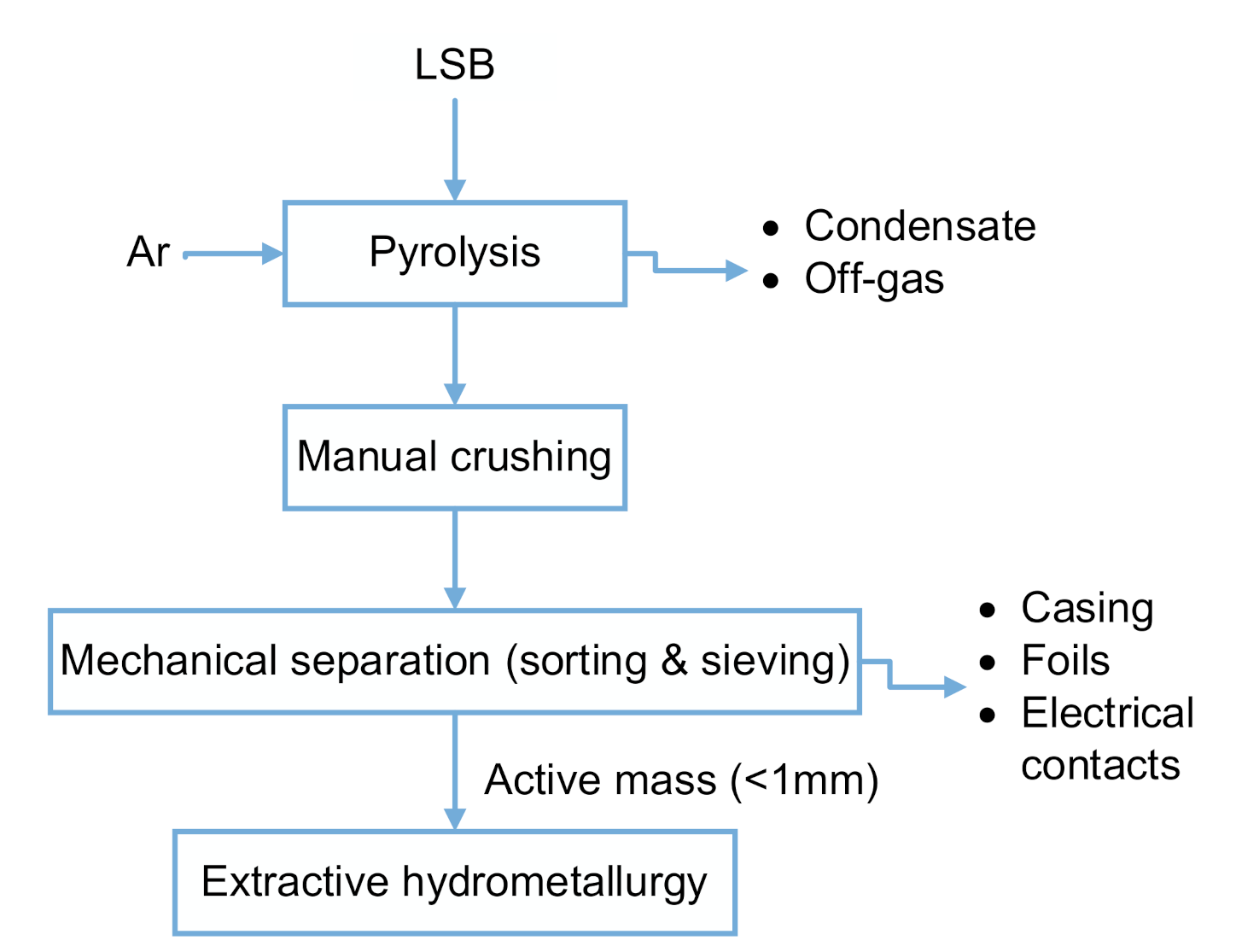
In order to enable a high selectivity and treat the rather ignoble LSB components with a combination from thermal treatment, mechanical treatment and hydrometallurgical processing is presented in this study, as shown in the process flow chart in
Figure 1.
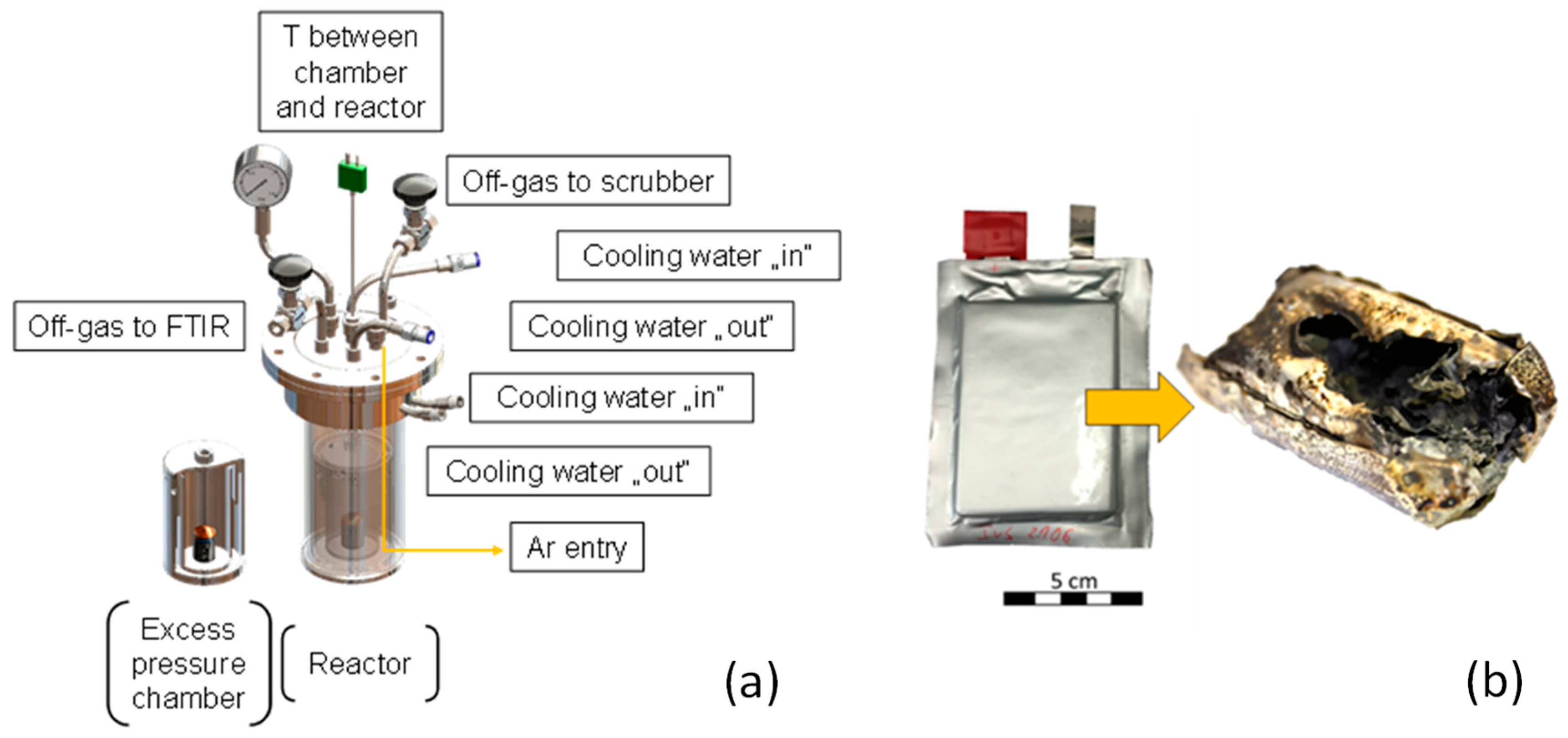
LSB pouch cells are provided by Fraunhofer IWS (see
Figure 2b), of whose every cell has a specific composition. The cells are pyrolyzed in a Thermostar resistance furnace (Thermostar, Aachen, Germany), which is flood with Argon to displace oxygen and, thus, avoids exothermal reactions with the environment. This incineration is to be prevented due to formations of {CO
2}, {SO
2}, and thus, active mass losses. A specifically constructed steel chamber with small holes ensures controlled off-gas release and hence prevents a sudden excess pressure. This chamber is placed in a closed and sealed steel reactor, which is then inserted in the furnace (see
Figure 2a). The off-gas can leave the system at two exit points: Firstly, two scrubbers in a row containing deionized H
2O clean the main off-gas stream, neutralizing acidic gases. The residual permanent gas leaves the reactor to an off-gas cleaning system. Secondly, an FTIR (Fourier transform infrared spectroscopy) analyzer (Gasmet Technologies Oy, Helsinki, Finnland) drains a defined volume flow from the off-gas for identifying gaseous phases. The pyrolysis temperature comprises 500 °C with a holding time of 1 h, which is continuously measured within the furnace and between the excess pressure chamber and steel reactor (see
Figure 2a).
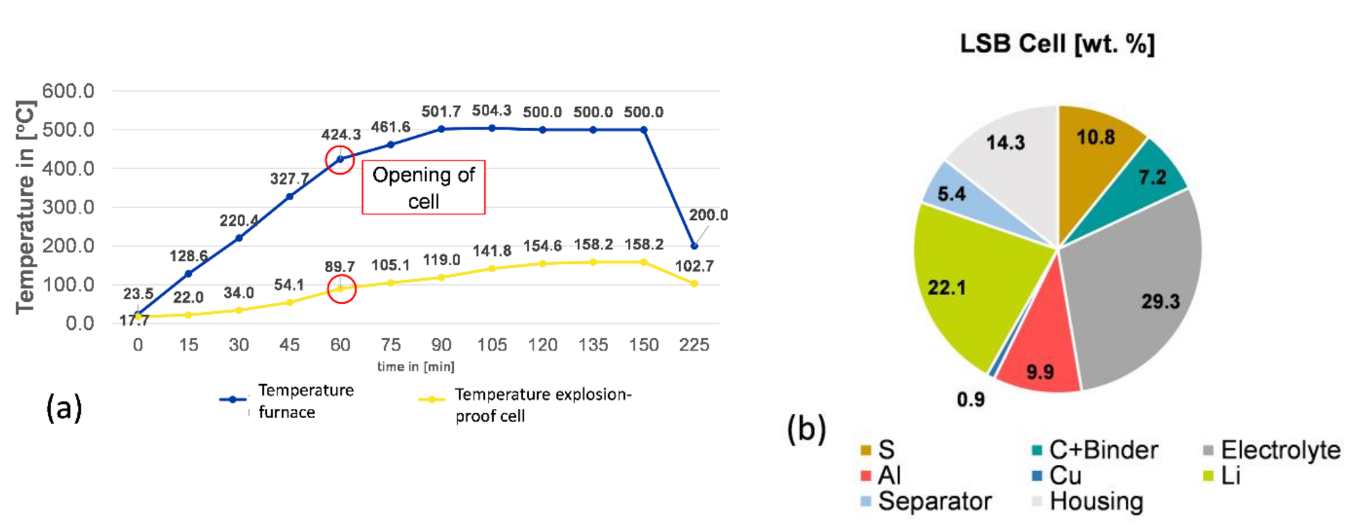
As
Figure 3 shows, the pyrolysis treatment leads to a cell opening temperature mean value of 90 °C, made visible by an abrupt rise in different gaseous phases, such as propene, methane, or formaldehyde.
Moreover, pyrolysis results in an averaged weight loss of 27.6%, due to the evaporation of volatile components stemming from electrolyte, separator, and binder. The next step comprises the manual separating of casing from the active mass and substrate foils in a glovebox. The downstream comminution by grinding in mortar is conducted, also in a glove box. The material still releases gaseous compounds, which can be toxic, such as H
2S. Furthermore, this treatment manner prevents metallic lithium from the anode from oxidizing. Subsequently, after separation and grinding, sieving is performed to extract the active mass of <1 mm, whose exemplarily composition can be seen in
Table 1. It has to be pointed out that heterogeneities persist both within the batteries due to the current research regarding their cell design, and also within the samples taken for analyzing active mass. The averaged, extracted active mass of a cell comprises 14.6 g. Therefore, calculating yields by extractive hydrometallurgy does not take the chemical analysis as reference but instead sums up the first filter cake and the first solution to get information about the real composition.
The chemical compositions within this study is measured by ICP-OES (Spectro, Kleve, Germany) for the present metals and by combustion method in the case of S and C, and combustion ion chromatography (CIC) in the case of F.
The hydrometallurgical process applied in this study in can be described as follows: The first step comprises a leaching with a subsequent filtration of the C-product, a precipitation including a subsequent filtration of copper sulfide, a pH adjustment for Al-precipitation, and a carbonation with a precipitation and a subsequent Li
2CO
3 filtration. The leaching step is conducted by different solvents, HCl, HNO
3, H
2SO
4, and NaOH. Here, carbon stemming from both cathode material and from pyrolysis soot is insoluble and, thus, can be filtrated. During leaching, 20 mL of H
2O
2 are added. Precipitation 1 makes use of the ongoing reaction between copper and sulfur. Cu has a high affinity to S, forming Cu
2S. During the leaching process S-containing gases are liberated and are transferred into a CuSO
4 solution. Here, copper matte is created, which is a precursor for copper production in the established Cu-production path, and then filtrated. The filtrate after the first filtration (C-filter cake) is colorless liquid free from solid particles (filtrate). The next step, precipitation 2, works by adjusting the pH using NaOH, KOH, or HNO
3, hence, basic solvents, to precipitate aluminum selectively. Some F-contaminations in the active mass due to abrasion of the steel pyrolysis reactor can be removed along with Al, since the Eh-pH diagram of Fe and Al show a possible precipitation in the same pH range [
48].
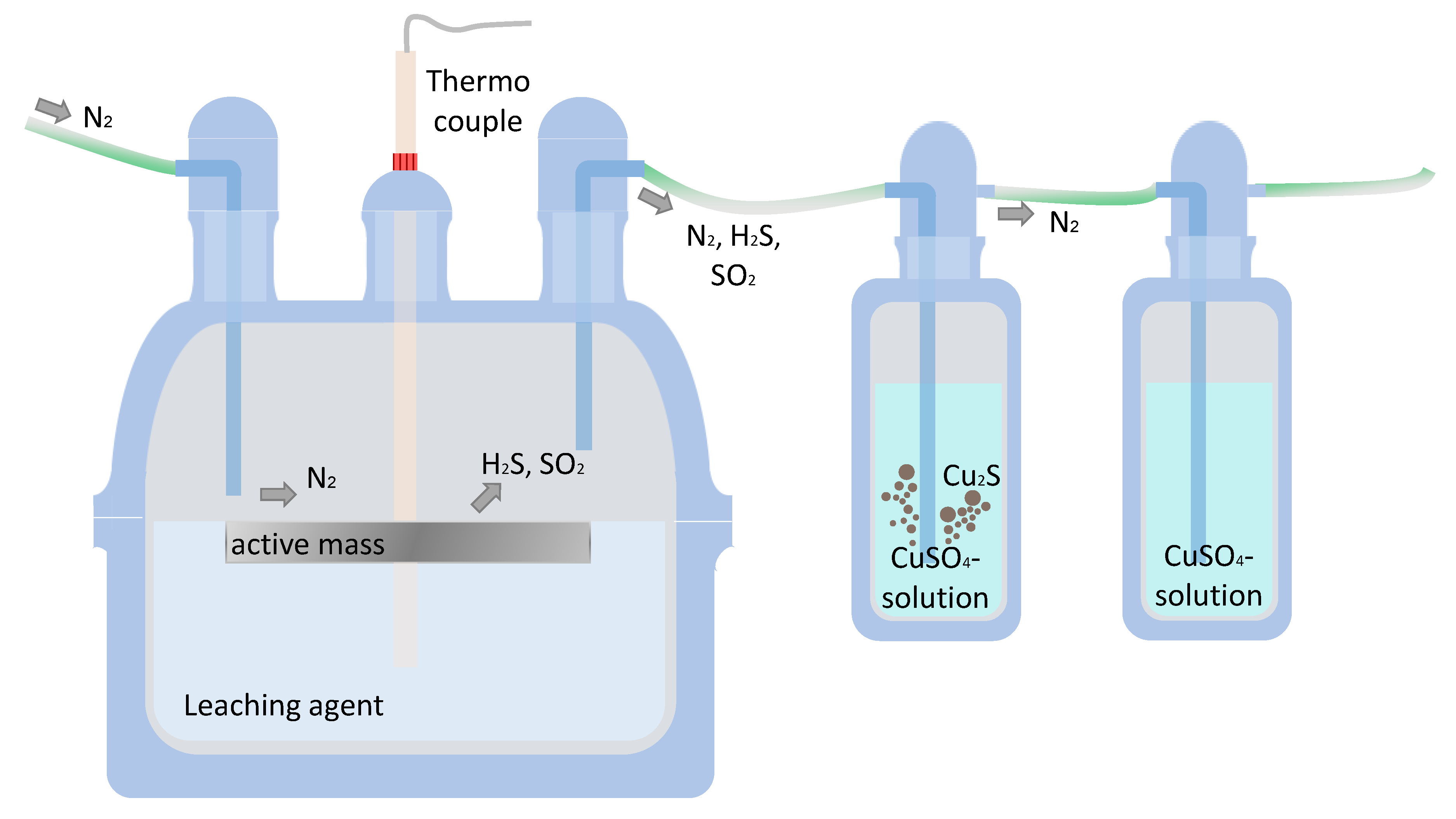
The process described can be visualized as follows (see
Figure 4):
Therefore, the pH value was increased to a value of 3, followed up by an addition of H
2O
2 to assure a dissolution of Al. Afterwards, the pH value was increased another time in an area to 5, where the best precipitation of Al and Fe is reported. Subsequently, the addition of Al(OH)
3 nuclei lead to a turbidity, representing the on-going precipitation. Before precipitation 2, 20 mL of H
2O
2 are added to the solution. The step “filtration 3” separates the generated precipitate. Precipitation 3 makes use of the Li carbonates’ property to have a lower solubility product at higher temperatures. Therefore, the amount of water can be reduced and therefore the formed Li
2CO
3 can precipitate. This behavior is promoted by the reduced liquid, in other words, approaching the solubility product. Thus, the last process step comprises a temperature increase to 100 °C, depending on the present pH value, followed by a slight pH adjustment in order to reach a neutral/basic area. As a side effect of the temperature increase, the solubility product of the formed Li
2CO
3 is reduced from 13.2 to 7.2 g/L [
49]. In this case, the pH value must be until ~7. Then, the addition of Na
2CO
3 leads to a pH increase in the area of ~9–10. This is also beneficial, because other studies have calculated a formation and thus precipitation of lithium carbonate in alkaline areas [
50]. Boiling and subsequent filtrating, namely filtration 4, of the solution enables lithium recovery as Li
2CO
3.
It is important to highlight the fact that different reactions occur, depending on the lithium sulfide compound as educt: During charging and discharging, different polysulfide phases arise, for example S8, Li2S8, or Li2S. Hence, the input phases have a direct impact on the ability to dissolve in aquatic media.
Figure 5 displays the reactor used for the first process sequence, namely the leaching step. An entirely sealed glass reactor fully transfers the arising gaseous phases into the CuSO
4 solution. This is crucial from a circular economy perspective, hence, for obtaining a maximum S recovery as Cu
2S, but also in terms of canalizing toxic off-gas products. The transfer from leaching reactor to the scrubbers is promoted by an N
2 carrier gas, which is led into the reactor area. During the leaching, both H
2S and SO
2 can be detected at the outlet of the second scrubber bottle. This shows an incomplete reaction between gas and product, but during leaching, the color of the CuSO
4 solution changed from blue into dark green, resulting in a solid precipitate. In virtue of the small input mass amount, the formed precipitate mass shows a few milligrams.
Table 2 displays an overview of the parameters examined within the conducted trials, resulting in 37 parameter combinations, where each set-up was performed one time within the pre-trial series (indicated as “VV1-29”) to perform a screening. The best-case scenarios were repeated within the main trials (indicated as EV1-3 and VD1-5).
3. Results and Discussion
For the following discussion, the focus is based on lithium yields, since lithium is the key driver for the recycling of LSBs, especially by value. Lithium values in filter cakes and solutions were detected by ICP-OES in a certified laboratory.
As already reported above, input analyses from the active mass show less accuracy due to the heterogenous chemical composition of the black mass/active mass. Bringing these aspects together, the lithium yields were calculated by summing up the lithium mass in every filter cake (fc) (C-fc, Al(OH)
3 fc and Li
2CO
3 fc), and the mass of lithium in the residual filtrate after filtration IV(Li
filtrate, IV). An alternative calculation would be summing up the lithium mass in the carbon filter cake (C -fc) and the lithium mass in the first filtrate (filtrate
I), but since this calculation leads to the same results, the first presented option was chosen. Finally, the calculation of lithium yields was performed as follows:
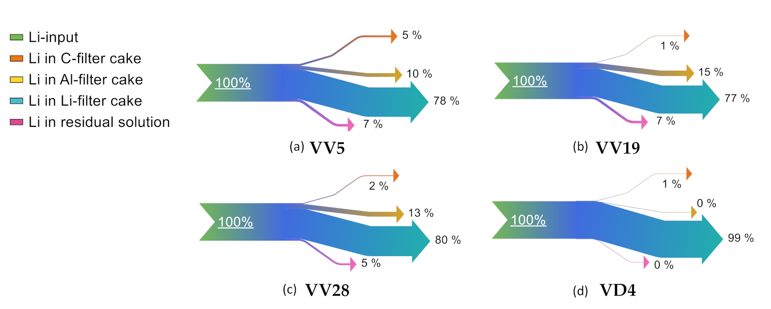
In order to visualize the distribution of lithium, exemplary Sankey diagrams reveal lithium distribution within the different filter cakes in
Figure 6 and
Figure 7. This behavior is explainable by the high reactivity of lithium, entering the leaching step also in metallic form stemming from the anode.
“VV5” shows the highest lithium losses in the C filter cake. This can be attributed to the room temperature leaching. “VD4” represents the lowest lithium losses within the Al filter cake. This can be explained by the amount of H2O2 added in the process step “pH adjustment and precipitation II”. In “VV5”, 15 mL H2O2 was added at once; whereas in “VV19”, 10 mL H2O2 was added in two 5 mL steps; in “VV28”, 10 mL H2O2 was added at once; and in “VD4”, 30 mL of H2O2 was added in three 10 mL steps.
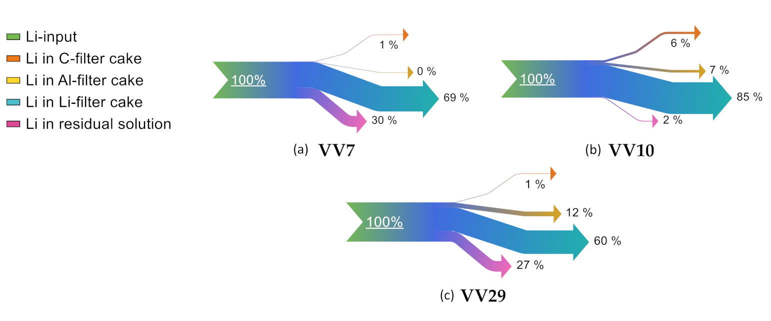
When comparing the leaching agents HCl, NaOH, and H2SO4 in terms of lithium distribution, only “VV10” shows low lithium losses within the residual solution. With regard to the impurity evaluation of lithium carbonate, it can be seen that “VV7” shows high shares of Cl, and “VV29” shows high shares of S and K. Thus, the formation of more stable phases suppresses the precipitation of lithium carbonate. The highest lithium losses in the C filter cake occur when using NaOH. This can be due to an incomplete dilution of lithium phases within the active mass in alkaline areas.
A qualitative X-ray powder diffractometry (XRD) evaluation shows the following main lithium phases within the pyrolyzed active mass (see
Table 3). However, it should be noted that within the samples, deviations can occur due to the state-of-charge and the post mortem cells history. This will consequently lead to different cell-internal reactions and different phases within the active mass.
Table 4 gives an overview on parameter combinations using H
2SO
4. It can be seen that 2- and 4-molar sulfuric acid was paired with NaOH and KOH.
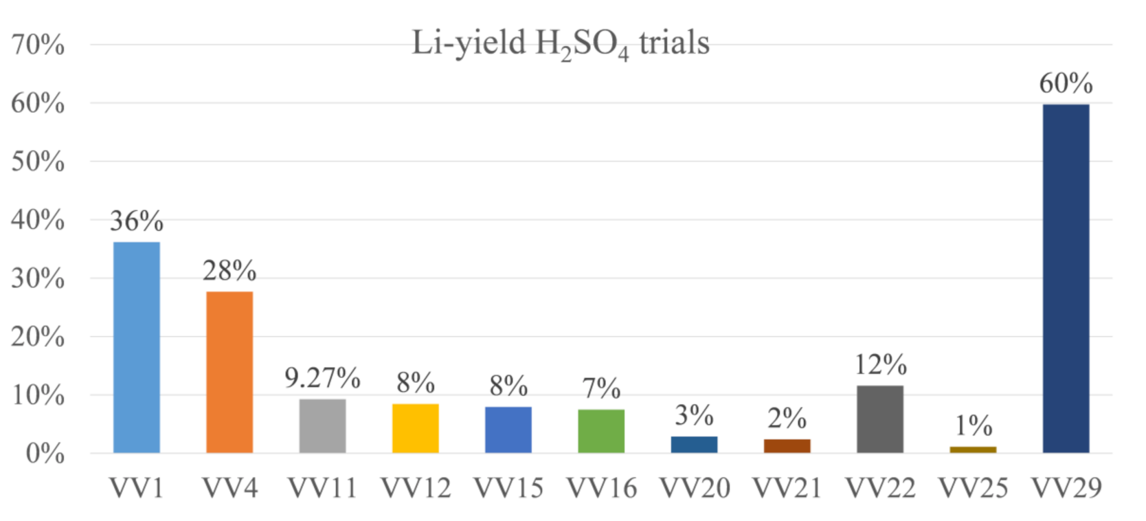
Figure 8 displays the yields of H
2SO
4 in terms of the pre-trials. It can be seen that the lithium yield has not crossed the 50% threshold in all trials, except “VV29”.
“VV29” differs from the other H2SO4-trials in terms of the pH additive used: in this case, KOH was used. In the other H2SO4-trials, lithium losses can be asserted to high contents either in the C filter cake but especially in the Al filter cake. However, most of the lithium remains in the residual solution and is therefore irrecoverable if the solution after the Li filter cake filtration will not be circulated or the filtration is not optimized. This is theoretically feasible to avoid losses but was not conducted here to keep the trial procedure constant among all trials.
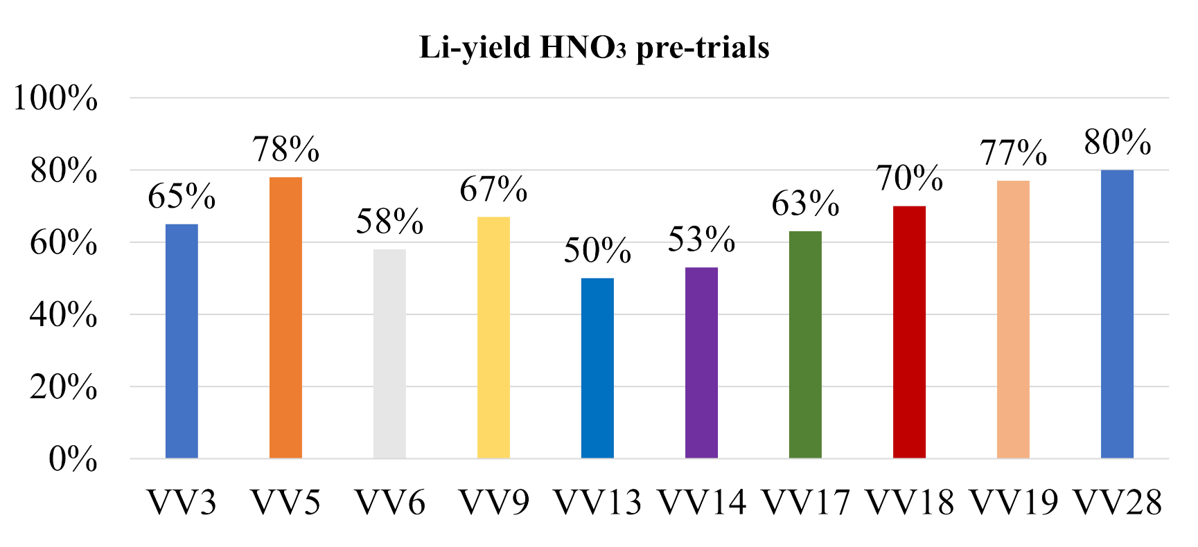
In contrast to that, the lithium yield by using HNO
3 shows in most cases a higher yield than 50%, as can be seen in
Figure 9.
Table 5 displays the matching parameters used for the HNO
3 pre-trials.
In the case of using NaOH as leaching agent, trials “VV10”, “VD1”, and “VD2” were performed.
Table 6 shows the parameter combinations tested.
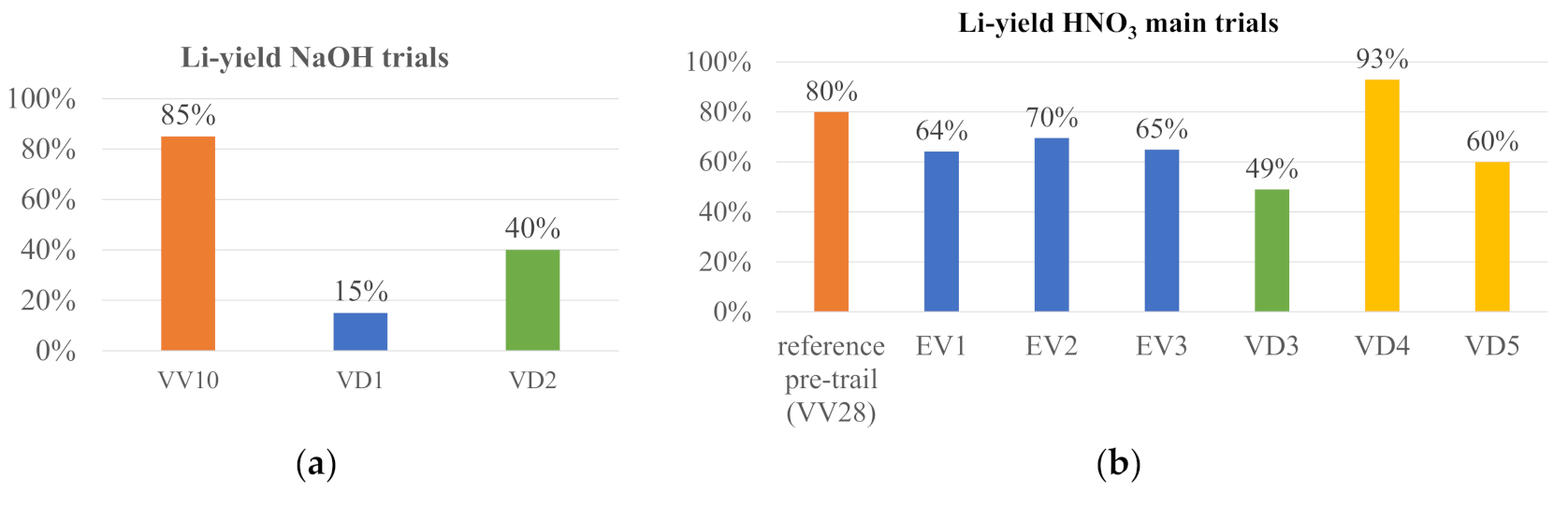
The NaOH trials show poor lithium yields, except “VV10”, as can be seen by
Figure 10a. The HNO
3 trials show the best consistency in yields, independent from the parameters chosen, as can be seen in
Figure 10b. “VD3” shows low lithium results, which can be explained by only use of an 8-molar acid. This concentration can, hence, be classified as an inadequate parameter.
In terms of lithium yields, it can be concluded that “VV5”, “VV19”, and “VV28” represent the best outcome with the leaching agent HNO
3 for the pre-trials, and “VD4” the best outcome for the main trials. In case of H
2SO
4, it is “VV29”, and in case of NaOH, it is “VV10”. “VV10” is different from “VD1” and “VD2”, since a leaching concentration of 4 mol/L was chosen, instead of 8 mol/L in “VD1” and “VD2”. In addition, the solid/liquid ratio shows an impact when comparing “VD1” and “VD2”: a solid/liquid ratio of 1:50 reflects higher lithium yields. The HCl trial shows a comparatively low lithium yield of 69%, in combination with high Cl contaminations within the lithium carbonate filter cake. Hence, this solvent was not used repeatedly and is therefore not represented in the bar charts. However, the parameter specifications for the best yields in
Table 7 give an overview on successful combinations.
Hence, it can be derived that the following parameters lead to enhanced Li yields:
HNO3 and NaOH reach the highest lithium yields. H2SO4 and HCl yields have not been satisfying when comparing all leaching agents in terms of lithium yields.
All best-case scenarios in show best results when leaching for 60 instead of 120 min.
Addition of H2O2 is beneficial.
Addition of Al(OH)3 as nuclei is suggested.
Since not only reached yields are decisive, arising lithium filter cake impurities are also to be focused upon. Hence,
Table 8 focuses on the chemical composition of several lithium carbonate filter cakes.
By evaluating the impurities, HNO3 and NaOH also show better results, especially trial “VD4”. Hence, another preferred parameter can be derived from the impurities’ evaluation:
KOH is slightly more suitable. “VV29” is excluded from this evaluation, since the leaching agent H2SO4 has not been suitable in yields, as well. Although “VV29” (H2SO4 leaching agent) represents an unsatisfactory result compared to other experiments, the highest Li recovery could also be determined in this experiment by using KOH.
According to
Figure 10 and
Figure 11, lithium shows the highest shares within the C filter cake among the HNO
3-trials when leaching at room temperature (“VV5”). Additionally, the sum of impurities is also higher in “VV5”, according to
Table 8. Thus, a leaching temperature at 60 °C is preferred. In addition, the yields of aluminum within the Al filter cakes were higher when applying leaching at 60 °C.
Due to the pre-trial results, the main trials “ED1-3” and “VD4-5” were performed with different process parameters based on the combination of KOH and NaOH. Moreover, “VV10” showed a high lithium yield. Hence, more trials with NaOH were performed within the main trials.
Table 9 gives an overview on the used parameters.
“VD1” shows low lithium yields (15%), which can be attributed to a higher solid/liquid ratio than both “VV10” and “VD2”. In addition, the direct comparison between a 4-molar NaOH (VV29) and an 8-molar NaOH (“VD2”) shows significantly lower yields for the 8-molar NaOH, so the parameter combination of a lower solid/liquid ratio and a lower molality (“VV10”) is the preferential combination. “VD3” has not reached high lithium yields due to its solid/liquid ratio of 1:20, the influence of the parameter combination of an 8-molar HNO
3 and the use of a 4-molar HNO3 cannot be detected at this point. The comparatively low lithium yields of “VD5” can be asserted to a high aluminum-containing input fraction. Only one third of the lithium in “VD4’s” input material is present in the input material of “VD5”, thus lithium losses in other filter cakes according to
Figure 8 and
Figure 9 have a bigger impact. As already reported above, the material used in this study shows a high degree of heterogeneity and especially within the trial set-ups of using a few grams per trial, a deviation within the composition can potentially change the system behavior.
From
Figure 10a and
Table 9, it can be derived that the trials VD1 and VD2, whose concentration was an 8-molar NaOH, could not lead to high yields. The pH additive was selected as follows: VD1 with an 8-molar HNO
3 solution and VD2 with a 4-molar HNO
3 solution. Thus, it can be concluded that the optimal parameter combination for NaOH consists of a 4-molar NaOH solution with a 4-molar HNO
3 pH additive.
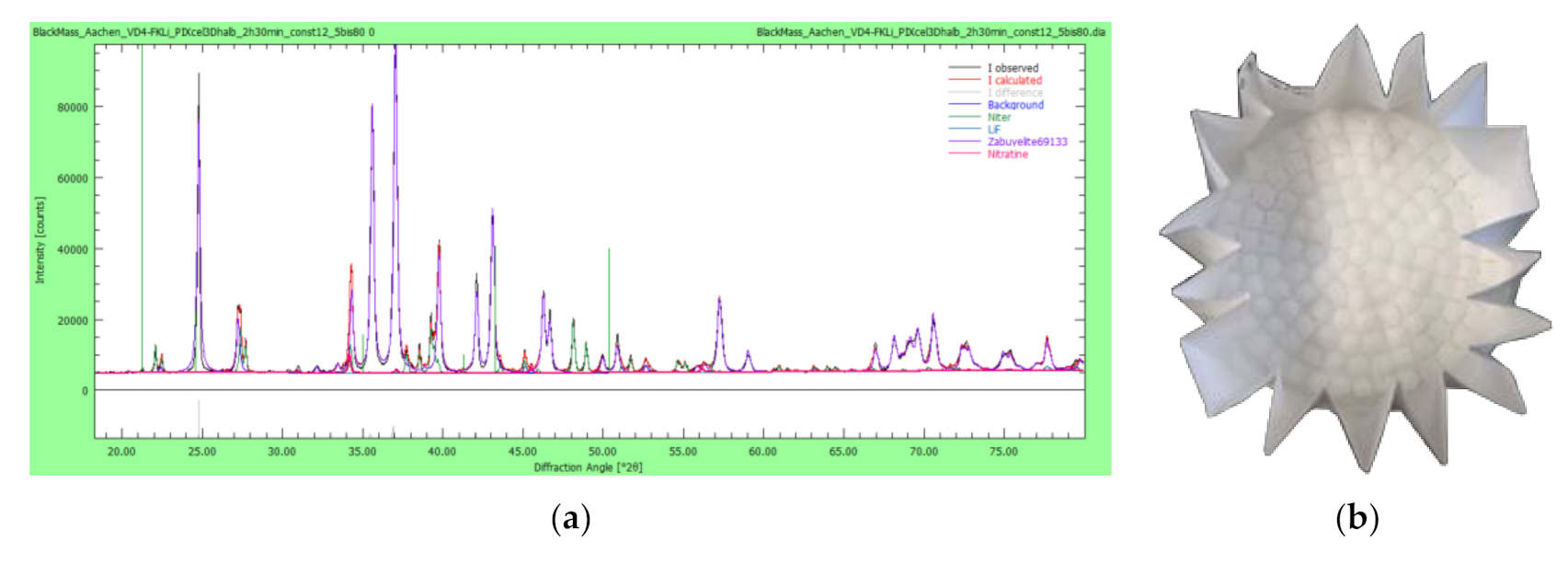
Since it is crucial for a further refining of the lithium filter cakes to gain knowledge on the prevalent phases, XRD analyses provide insight into the presence of lithium carbonate and impurities on a phase level. This is exemplarily shown by the XRD analysis of VD4’s lithium filter cake (see
Figure 11a). Here, mainly Li
2CO
3 but also LiF, KNO
3, and NaNO
3 are present. The impurities containing KNO
3 can be asserted to the use of KOH as pH additive, and the impurities containing NaNO
3 can be asserted to the addition of Na
2CO
3 for forming Li
2CO
3.
VD4 shows the highest lithium yields, while the chemical composition of the other filter cakes, namely C filter cake, CuS filter cake, Al filter cake, and lithium carbonate filter cake are to be found in
Table 10. VD4 is chosen exemplarily for efficiency reasons. Here, “fc” indicates the filter cakes, and no oxygen and hydrogen can be detected by ICP-OES, while the sum of detected elements is not 100%.
The majority of C enriches within the C filter cake that the principle of S recovery as copper sulfide was successful, and Al mostly precipitates in the Al filter cake. Interestingly, also F is mainly leaving the aqueous system along with the Al filter cake. This is explainable by the formation of Al–F-containing phases, such as AlF3, but needs to be proven by XRD analysis. Besides the high S-shares, which have already been discussed before, the set-up of VD4 shows a proof-of-concept of this study’s scope.
According to the elemental distribution of the obtained filter cakes in
Table 10, the filter cakes obtained from HNO
3 leaching with KOH as pH additive are visualized in
Table 11. In the C fc, metallic Al flakes are still visible, since metallic Al indicates a low leaching efficiency for metallic Al. The color of the CuS fc together with the chemical composition in
Table 10 suggests the formation of CuS or Cu
2S. Some CuSO
4 shares are also possible but further XRD analysis would be needed to investigate this. The Al fc color suggests the formation of Al(OH)
3 and AlF
3.
Finally, a process for lithium recycling from lithium–sulfur batteries was proven: A combination of pyrolysis, manual extraction of black mass, and subsequently, leaching of black mass in HNO3 have shown lithium yields of 93%, with a Li2CO3 purity of 92.78%. H2SO4, HCl, and NaOH, which were validated as suitable leaching agent for Li-ion battery active mass, show poor results for lithium–sulfur batteries.
4. Outlook
For future research, several aspects are to be investigated further: A repetition of the set-up in trials “VV10”, “VV28”, and “VD4” for statistical validation will be one focus. These set-ups are indicated in
Table 11 as “3×”, representing three repetitions. Besides these repetition trials, different set-ups in terms of detailed HNO
3 investigation will be added. These parameter combinations are indicated in
Table 11 as “1×”, representing one trial. The combination of 4-molar HNO
3 with 8-molar KOH is neglected due to the comparatively low yields in “ED1-3”. Although the combination of 8-molar HNO
3 and 2-molar KOH as pH additive was investigated in “VD3”, it will be tested again with a more promising solid/liquid (S/L) ratio. An overview on the trials to be performed as next steps is given in
Table 12.
The most successful set-up in terms of
Table 11 will be performed with the battery fraction > 1 mm, as well, since in Li–S batteries, lithium distributes between the fine fraction (black mass) and the coarse fraction (>1 mm) by almost 50:50.
Moreover, another carrier gas could be used instead of N
2 in order to avoid a possible formation of Li
3N. Ar is a suitable replacement in this case. In addition, the CuSO
4 solution in the gas washing bottles could be replenished with a basic additive, improving the scrubbing effect. This then leads to a further reduction in gaseous emissions, such as HF and H
2S. On the other hand, another chemical additive is then required. With the set-up described in this study, hence without basic additive, (see
Figure 5), 5 ppm of H
2S and 3 ppm of HF were measured after the second washing bottle. In addition, the C fc could be treated to remove the remaining sulfur. On the other hand, a refurbishing of the cathode for second use in LSBs is thinkable. For the detection of C-within solutions, a Total Organic Carbon (TOC) analyzer will be used.
Moreover, waste water should be avoided by recirculating the residual filtrate after Li2CO3-filtration. Besides waste reduction, it also implies the benefit to minimize lithium losses.
Another strategy for an early-stage lithium recovery (ESLR) has shown good results for conventional Li-ion batteries and will also be investigated for Li–S batteries. This can be realized by using CO2 for lithium carbonation before using acidic media or also as a substitute for Na2CO3.
For a better understanding of on-going reactions within the hydrometallurgical processing, equipment for online measurement of both ionic concentrations and potential is going to be applied. Thus, the area of Eh-pH diagrams can be asserted more effective, and especially the lithium precipitation can be designed more accurately: Na- and K-ion concentration can be detected to filtrate solution before the solubility product of both ions is reached, avoiding impurities within the Li filter cake. For better post-processing, XRD analyses of the C filter cake, the CuS filter cake, and the Al filter cake are to be evaluated, as well.


