Article

The Mini Blast Furnace Process: An Efficient Reactor for Green Pig Iron Production Using Charcoal and Hydrogen-Rich Gas: A Study of Cases

by
Jose Adilson de Castro
1,2,*,
Giulio Antunes de Medeiros
1,
Elizabeth Mendes de Oliveira
3,
Marcos Flavio de Campos
1 and
Hiroshi Nogami
2
1
Graduate Program on Metallurgical Engineering, Federal Fluminense University, Volta Redonda, Rio de Janeiro 27255-125, Brazil
2
IMRAM-Institute of Multidisciplinary Research for Advanced Materials, Tohoku University, Sendai 980-8577, Japan
3
Federal Center for Technological Education Celso Suckow da Fonseca, Angra dos Reis, Rio de Janeiro 23953-030, Brazil
*
Author to whom correspondence should be addressed.
Metals 2020, 10(11), 1501; https://doi.org/10.3390/met10111501
Submission received: 15 July 2020 / Revised: 4 November 2020 / Accepted: 8 November 2020 / Published: 11 November 2020
(This article belongs to the Special Issue Challenges and Prospects of Steelmaking Towards the Year 2050)

Abstract

:
The mini blast furnace process is an efficient route to produce pig iron based on the burden with granulated charcoal. New, improved technologies have recently been introduced in the mini blast furnace process, such as pulverized charcoal and gas injections, new burden materials, and peripheral devices that improve the overall process efficiency. In this paper, we revise the new injection possibilities and discuss new aspects for further developments. The analysis is carried out with a comprehensive multiphase multicomponent mathematical model using mass, momentum, and energy conservation principles coupled with the rate equations for chemical reactions, multiphase momentum, and heat exchanges. We analyze new technological possibilities for the enhancement of this process as follows: (i) a base case of pulverized charcoal injection with industrial data comparison; (ii) a set of scenarios with raceway injections, combining pulverized charcoal with hydrogen-rich fuel gas, replacing granular charcoal in the burden; (iii) a set of scenarios with hydrogen-rich gas injection at the shaft level, replacing reducing gas in the granular zone of the reactor; and the possible combination of both methodologies. The simulated scenarios showed that a considerable decrease in granular charcoal consumption in the burden materials could be replaced by combining a pulverized charcoal injection of 150 kg/tHM and increasing rich gas injections and oxygen enrichment values, decreasing the specific blast injection and granular charcoal. The productivity of the mini blast furnace process was increased for all scenarios compared with the reference case. We review the aspects of these operational conditions and present an outlook for improvements on the process efficiency.

Graphical Abstract

1. Introduction

Renewable energy in the ironmaking industry is an important issue to develop the modern industry. In the steelmaking production routes, the carbon-based processes are predominant [1,2,3,4,5,6,7]. In this sense, the pig iron production step could significantly drive a new green steelmaking technology. The charcoal mini blast furnace process is an established technology. Although the charcoal blast furnace has been regarded as old technology, modern auxiliary and peripheral equipment have been introduced and greatly improved this technological route for hot metal production [2,4]. The mini blast furnace’s efficiency based on granular charcoal has continuously been improved with the introduction of proven technological advancements formerly developed to the large blast furnaces based on coke operation and prepared burden materials [2,4]. The mini blast furnace’s efficiency is strongly dependent on the fuel and reducing agent quality and the preparation of the burden materials [4]. The granular charcoal quality is variable and depends on several aspects of the biomass production and the carbonization processes. Recent improvements in the technology for biomass production have been widely reported for other sectors of applications. However, the mini blast furnace process must obtain new improvements due to its specific requirements. Moreover, the technology of pulverized materials injections in the tuyeres of large blast furnaces has achieved stable and efficient operations for quite a long period [4,8,9,10,11,12,13,14,15,16,17,18,19]. The technology enhancements for pulverized biomass injection require special attention, mainly on the grinding and pneumatic transportation systems.
The available technologies for the large coke-based blast furnaces have continuously being improved through applying novel digital paradigms [9,10,11,12,13,14,15,16,17,18,19,20]. The improvements have been mainly driven by demands to decrease the specific carbon, restrictions on the available raw materials quality, and demand for the high quality of reducing agents and renewable energy sources [7,8]. However, the total amount of fossil carbon required to produce pig iron using the coke-based blast furnace route is becoming prohibitive. The main restriction to the coke-based blast furnace process is global warming trends with a strong demand for low carbon technologies. Hence, alternative routes that minimize the fossil carbon used in the process are attractive and challenging, allowing the researchers and developers to propose several computational-based approaches. The hydrogen and the oxygen-based blast furnaces processes are recently in vogue and promise to positively impact the steel industry [2,4,5,6,7]. The developing technologies have demonstrated effectiveness in reducing CO2 emissions. However, the effective cost of hot metal production and hydrogen-rich gas and oxygen availability are still barriers to effective implementations. The Brazilian hot metal industry has a long experience with the mini blast furnace’s technology operating with high productivity, solid and liquids flow stability, and raw materials supply logistics. Recently, several small and compact granular charcoal-based blast furnaces, which used to operate only with granular charcoal produced by the carbonization process of eucalyptus wood, are incorporating and adapting new pulverized injection facilities and incorporating an off-gas treatment efficient cooling system, enhanced refractories, tapping technologies, and an efficient blast heating system [2,4]. These technologies are becoming viable due to the lowering of the investment cost and the high possibility of increasing efficiency and productivity. The mini blast furnace technology is considered net carbon-free, assuming a complete carbon cycle based on the intensive eucalyptus plantation of about seven years with high productivity in tropical countries pursuing the available land area. The technologies for addressing the carbonization of various biomasses have also been continuously improved over the years and have contributed to new carbon renewable sources. New pulverized charcoal sources can be available shortly using other plantation species with a smaller life cycle and higher productivity.
The mini blast furnace process analysis has been performed by several researchers using a variety of methodologies [12,13,14,15,16,17,18,19,20,21,22,23,24,25,26]. Nonetheless, the empirical and theoretical approaches aiming to analyze appropriate operational practices using variable sources of raw materials require a comprehensive approach using detailed models.
The use of sophisticated and comprehensive mathematical models based on transport phenomena principles that consider detailed chemical reaction mechanisms and rate equations demands time-consuming computations [18,19,20,21,22,23,24,25,26,27]. This approach is particularly useful for studying the impacts of multifactorial aspects of testing a new technological concept. For example, the operational practices have been dramatically improved by using operational diagrams based on mass and energy zone balances applied to the process analysis or models based on statistical and data analysis to implement control tools and automatization after the new modern industry concept. Nevertheless, further improvements and detailed analysis are only possible by applying comprehensive mathematical modeling, which uses fundamental equations based on conservation principles of mass, momentum, energy, and detailed chemical species. The present study uses this methodology. A considerable number of mathematical models to predict the large coke-based blast furnace operations and pulverized coal injection have been developed and shown their ability to predict the actual operation. These are currently used to recommend new technologies that improve the efficiency of the processes [12,13,14,15,16,17,18,19,20,21,22,23,24,25,26,27]. These continuous developments have maintained the coke-based blast furnace process as the leading technological route to produce pig iron for a long period. The tendency is that this route will still be dominant in the near future. However, other competitive reactors have been developed and proved commercially profitable, depending on local conditions [7,27,28,29]. Comprehensive mathematical models to predict the mini blast furnace process based on charcoal operation are scarce in the current literature. Some of the recent attempts were addressed by Matos et al. [30] and Castro et al. [4,21].
The focus was to analyze the granular charcoal-based mini blast furnace process’s actual operating conditions in their works. In the current study, we established new mathematical modeling, which considers six phases and their mutual interactions of momentum, mass, and energy. New rate equations are included in the model with their respective individual chemical species. The model employed the representative elementary control volume concept, which is especially valuable to deal with the simultaneous coexistence of the phases in the lower part of the furnace under pulverized charcoal injection conditions. Figure 1 schematically shows the theoretical approach for dealing with the complex and simultaneous motion of gas, solid, pulverized charcoal, hot metal, and slag coexisting in the same representative control volume and the corresponding interphase interactions of momentum, mass (chemical species), and energy. This model differs from the previous attempts due to the new phase implemented to account for the pulverized charcoal injection and the new chemical species and the implementations of the chemical reactions involving the new phase and chemical species.
Additionally, new operational conditions with high pulverized charcoal injection are analyzed. In this study, the hot hydrogen-rich gas injection is addressed for analyzing the mini blast furnace process. The impacts on the inner reactor variable’s distributions are discussed in the view of the carbon intensity parameter, which is defined as the total amount of carbon used to produce a unit of pig iron, as a parameter for low-carbon technological analysis. The operational practices and scenarios analyzed in this study are fully based on a renewable source of carbon and hydrogen-rich gas. Thus, the mini blast furnace process product could be referred to as the green pig iron.

2. Materials and Methods

Methods for analyzing the mini blast furnace process based on simulation tools have been continuously developed since the last century. This paper presents a comprehensive multiphase, multicomponent model based on the full physical and chemical interactions with the consideration of detailed rate equations accounting for the kinetics of the chemical reactions and phase transformations dynamically coupled with the internal state variables of the mini blast furnace reactor. The model is coupled with the thermophysical properties of the phases and chemical species being locally considered. Figure 1 presents the concept of the multiphase and multicomponent approach. In this concept, the process’s inner state variables are associated with a representative volume of the bed so that the phases can coexist. The phases present their own chemical species and thermophysical properties, which are dynamically changed during their motion inside the reactor. The phases interact with one another, exchanging momentum, mass, and enthalpy through interfaces phenomena, chemical reactions, and phase transformations. The phases and interactions considered in this model are illustrated in Figure 1b.
The solid lines connecting two phases represent full interactions of mass, momentum, and energy between the phases. The dotted lines indicated that a simplified model for momentum interactions are assumed besides the full interactions for mass and chemical reactions. The gas-phase includes the blast chemical species and those generated with the reactor due to the chemical reactions. The solid phase includes all the granular materials charged in the furnace through the burden materials charging system (granular charcoal, lump ore, sinter, small sinter, pellets, and slag agents). The pulverized charcoal (PCH) corresponds to the pulverized material injected through the tuyeres’ injection lances. The hot metal (HM) comprises the liquid reduced materials that form the liquid pig iron. The slag is formed by the liquid oxides incorporated during the melting down phenomenon, silicon transfer, phosphorus, manganese, and other chemical reactions during alloy elements incorporated in the pig iron. The fines are regarded as the fine particles produced during the burden materials degradation and carried by the upward gas flow. Thus, fines can be formed by all the chemical species present in the burden materials and those formed during the solid transformations.
The phases and their chemical species are presented in Table 1. The chemical reactions involve the multiphase and multicomponent mass transfer, accompanied by momentum and heat, depending on the local rate equations and specific mechanisms. The chemical reactions and phase transformations considered in this model are listed in Table 2. The rate equations considered for these reactions were implemented using available models and data previously tested and adapted by the authors from the literature [2,4,5,8,9,10,11,12,13,14,15,16,17,18,19,20,21,22,23,24,25,26,27,28,29,30,31,32,33,34,35,36,37,38,39,40,41,42,43,44,45]. The momentum and energy interphases exchanges are modeled based on fundamental relations using local flowing conditions [8,31,34,35,36]. These relations were adapted to the mini blast furnace conditions [2,4]. The boundary conditions and analysis cases are specified, obeying the mini blast furnace’s actual operation practice using a pulverized charcoal injection system and peripheral facilities.
Mass and energy transfer mechanisms are locally considered in the rate equations, resulting in a complex and coupled kinematic model, allowing the model equations to compute variable raw materials and operational conditions. A complete kinetic database for a range of raw materials used has been constructed in this sense. As the model implementation is done in an open-source computational code, new kinetic data have been continuously developed and updated in the model based on both experimental work and industrial trials [2,4]. Therefore, it is worthy to emphasize that the capability of the model prediction and its accuracy have been continuously enhanced, with new implementations and consistent experimental data incorporation to new raw materials.
The kinetic models’ fundamentals were implemented using the same model structure but with a new constant rate. The parameters were adjusted for the new materials’ experimental data obtained under controlled dimensionless parameters. Therefore, the computational code and simulation tools are open and able to consider the raw materials availability’s continuous changes. Thus, a useful computational code for the analysis of the process is welcome. Using this model, we can predict the value of using a new raw material in the green pig iron production route based on its performance in the process. Moreover, it is possible to determine the operational conditions that maximize the new raw materials’ competitive characteristics’ efficiency. Some new features are included in this paper as reacting to new species and their corresponding new rate equations. It is necessary to obtain suitable rate equations for the reactions taken under the mini blast furnace environment conditions regarding the biomass utilization. These rate equations were based on the previous studies and adapted for the mini blast furnace process conditions under hydrogen-rich gas and pulverized charcoal injections [2,4,8,9,10,11,12,13,14,15,16,17,18,19,20,21,22,23,24,25,26,27,28,29,30,31,32,33,34,35,36,37,38,39,40,41,42,43,44,45].

2.1. The Multiphase and Multicomponent Model Equations Applied to the Charcoal Mini Blast Furnace Reactor

The model formulation assumes that the conservation principle holds in the calculation domain. The phases are denominated as continuous and discontinuous for accounting for the phases interactions. The model is based on a set of conservation equations for momentum, energy, and chemical species of the coexisting phases, summarized in Equations (1)–(7).
Momentum and continuity of continuous phases:
( ρ i ε i u i , j ) t + ( ρ i ε i u i , k u i , j ) x k = x k ( μ i u i , j x k ) P i x j F j i l
( ρ i ξ i ) t + ( ρ i ξ i u i , k ) x k = m = 1 N r e a c t s M n r m
Momentum and mass conservations of discontinuous phases:
( ρ i ε i u i , j ) t + ( ρ i ε i u i , k u i , j ) x k = ρ i ε i g j F j i l
( ρ i ξ i ) t + ( ρ i ξ i u i , k ) x k = m = 1 N r e a c t s M n r m
Conservation of the phase’s chemical species:
( ρ i ε i φ n ) t + ( ρ i ε i u i , k φ n ) x k = x k ( D n e f f   φ n x k ) + m = 1 N r e a c t s M n   r m
Conservation of the phase’s enthalpies:
( ρ i ε i h i ) t + ( ρ i ε i u i , k h i ) x k = x k ( k i C p i   h i x k ) + E i l   + m = 1 N r e a c t s Δ h m r m
Restriction for consistency of coexisting phases’ volumes fractions:
i = 1 N p h a s e s ε i = 1
The x variable represents the physical coordinates with the indexes i, j, and k representing the coordinate directions. The phase properties ρ ,   ε ,   μ are the effective density, volume fraction, and viscosity with the indexes i and l accounting for the phases. The variables u, P, and F stand for the velocity component, pressure, and interphase interaction forces with the indexes i and l indicating the phases and j and k indicating the coordinate directions. M and r are the chemical species molecular weight and the chemical reactions rates, with the indexes n and m representing the chemical species and their respective chemical reactions. The variables φ ,   D n e f f are mass fractions and effective species diffusion coefficient of the chemical species within the phases. E ,   h ,   k ,   C p and Δ h are the heat interphase exchanges, phase enthalpy, thermal conductivity, specific heat capacity, and enthalpy of reactions, respectively.
Table 1 lists the phases and their chemical species considered in this study. The solid phase is divided into burden components with their own compositions and chemical species, undergoing particular chemical reactions kinetics. The rate parameters obtained from experimental work are carried out under similarity, enabling the modeling implementations’ scaleup. Thus, the fundamental theoretical principles are compatible with the reactor conditions and can be applied to model the whole process features.
The set of partial differential equations is resolved, assuming the boundary conditions representing the mini blast furnace conditions with the process monitoring’s operational data. Therefore, the boundary conditions are applied to the computational domain boundary delimitated at the bottom by the slag surface, at the top by the burden surface profile, and by lateral walls. At the top, the gas phase is assumed as a fully developed flow, and solid inflow is modeled based on the inflow rate given by local solid mass consumption due to chemical reactions and melting or gravity-driven flows. At the tuyere injection, the blast’s inlet, additional oxygen, hydrogen, or fuel gas, and pulverized charcoal are given by their inflow rates.
The blast flowrate and gaseous fuel injection are fixed. In contrast, the pulverized charcoal injection is iteratively calculated to reach the aimed injection rate, which is specified at the beginning of the iterative calculation [2,4]. At the sidewall, mass fluxes across the wall are assumed null. At the same time, heat loss is allowed by setting an overall cooling heat transfer coefficient based on the cooling water system’s temperature variation and flow rate using the operation’s acquisition data.
The source terms appearing in the momentum equations are calculated using sub-models based on semi-empirical correlations obtained under blast furnace conditions. The gas-solid momentum interactions consider the local layer structure evolution inside the reactors. The evolution of their volume fractions traces the solid component’s coexistence within each representative control volume. The solid phase properties are calculated by taking into account the mass fractions of the chemical species within the solid component pondered by their volume fractions in the solid phase components. In this sense, the layer structured descending properties in the burden is locally considered by tracing the solid components burden layer and their volume fractions, accounting for the solid layer local motion dynamics.
i = 1 s o l i d ε i = ε f o + ε f s + ε f p + ε f b + ε f c = ε s
The variables ε f o ,     ε f s ,     ε f p ,     ε f b ,     ε f c ,     ε s represent the volume fractions of the burden materials in the solid phase, lump ore, sinter, pellets, briquets, granular charcoal, and the total amount of the solid phase using the additive rule, respectively. The volume fractions of the burden materials are calculated using the burden layers’ evolution within the furnace using as inlet boundary conditions the burden structure calculated depending on the charging practice [4,8].

2.2. Numerical Solution of the Conservation Equations

The numerical method selected to resolve the transport equations is based on the finite volume method (FVM). The formulation is developed in a general non-orthogonal coordinate system to account for the accurate geometry of the physical space domain [46,47,48]. The numerical mesh is constructed using the body-fitted coordinate system to accurately describe the blast furnace wall shape [48].
To resolve the coupling of the governing equations of mass and momentum of the continuous phases, the SIMPLE (Semi-Implicit Method for Pressure-Linked Equations) algorithm is applied on a staggered grid frame using covariant projections of the velocities. The numerical calculation of the discretized equations’ coefficients is the widely used power-law scheme [47,48]. The discretized algebraic equations are solved using the line-by-line method based on the iterative procedure constructed using the tridiagonal matrix solver. This procedure allows the tridimensional calculations with strongly no-linear differential equations [46,47,48].
The iterative procedure used to couple the discontinuous phase motions use the momentum equations calculations with the phase volume fractions iteratively calculated by the phase’s total mass conservation. In the iterative procedure of the momentum and volume fraction momentum equations, the numerical coefficients are calculated combining the power-law scheme for the momentum equations and the upwind scheme for the volume fraction based on the mass balance of the corresponding phase. For all chemical species in the phase calculations, the numerical procedure assumes the power-law scheme using iterative calculations [8,46,47,48].
Each phase’s enthalpy conservation equations are calculated, coupling the mass and enthalpy exchanges using the rate equations for the chemical reactions. A polynomial function relating to the phase enthalpy and its temperature are constructed based on the local composition. The specific heat capacities of the chemical species are locally used, assuming the additive rule. The secant method is used to obtain the polynomial equations’ real roots to obtain the temperatures of the phase [8].

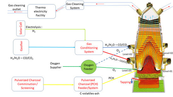
2.3. A New Concept for Hydrogen-Rich Gas Injections in Two Tuyeres Levels of the Charcoal Mini Blast Furnace

The rich gas hydrogen injection can be used to replace the reducing gas at the shaft of the furnace or as fuel gas at the raceway. Figure 2 shows these two concepts schematically. Figure 2a presents the possible injection simultaneously at the raceway level and the second injection level at the beginning of the shaft. Figure 2b shows the concept of using hydrogen-rich fuel gas injection in a separate lance at the tuyeres in the raceway region. These practices are substantially different and have strong effects on the whole blast furnace operation. Although some attempts to analyze these possibilities have been proposed, the analysis has been carried out simplified models and experiments that did not consider the complex changes that the whole blast furnace undergoes. Thus, using a comprehensive total blast furnace model using the multiphase and multispecies interchange principle is adequate.
In our previous model, we implemented the new features and chemical reaction to consider the coupled phenomena involving all the phases and chemical species listed in Table 1 and Table 2. The rate equations for the chemical reactions were obtained using experimental data and available rate equations previously published [2,4,8,9,10,11,12,13,14,15,16,17,18,19,20,21,22,23,24,25,26,27,28,29,30,31,32,33,34,35,36,37,38,39,40,41,42,43,44,45]. To investigate these new conditions, we examined four cases of increasing injection at the second level, four injection cases at the raceway, and combined cases of both. These cases were compared with a reference case of actual operation in a mini blast furnace with 390 m3 of inner volume with a long experience of operation with high rates of pulverized charcoal injection, and granular charcoal charged using a double-bell system with moving armor to control the thickness of the layers.

3. Results and Discussion

In this study, we analyze these possibilities of injection organizing into three sets of calculations. Firstly, a reference case using the actual operation is adjusted, and the measured data are used to compare the calculated results. A good accurate reference case is an important step to guarantee the model’s reliability and sensibility against controllable operational conditions such as blast, burden materials, and suitable boundary conditions. Two other sets of analysis cases were considered as well as the combination of both. These cases cover the increasing amount of injections at the shaft level and raceway and necessary adjustments on the oxygen and vapor supply.
The composition of the injected gases at shaft and tuyeres levels are specified, as shown in Table 3. The mixed gases are obtained from the gasification of torrefied biomass of eucalyptus under water vapor to obtain a high H2 content. The experimental trials used pressurized gas to inject in the shaft and tuyere levels. The effects of these injection possibilities are discussed in the view of the fully operational status. The chemical composition of the burden materials used is listed in Table 4.
The shaft gas presents high H2 and CO concentration and other hydrocarbons with small quantities of impurities. The injection temperatures were maintained at 1050 °C for all calculations. The hydrogen-rich gas injection at the tuyere has calorific values compatible with a fuel of medium value of traditional pulverized coal but negligible impurities and controlled humidity.
The burden materials are composed of granular charcoal, sinter, pellets, briquette, and lump ore. The charging practice and materials proportions to form the layer structure depend on the operational practice and the materials’ availability. In this study, all the calculations assumed the same proportion used in the reference case (sinter: 65%, pellet: 20%, briquette: 10%, and lump ore: 5%). As shown in Table 4, the volatile matter in the granular charcoal and pulverized charcoal are present with significant amounts and important parameters to determine the solid carbon source’s heat input.
However, it is worth mentioning that all the carbon source used in this mini blast furnace process is renewable, as it was obtained from the planted forest’s carbonization process. Nevertheless, the partial replacement of the granular charcoal is attractive to widen the fuel and reducing agent available to the process with the possibility of combining gasification processes of a variable source of biomasses and allow this technology also to include other sources of hydrogen in the ironmaking processes. The pulverized charcoal system comprises comminution facilities and pneumatic transportation in a closed circuit to attain particle size and composition homogeneities. To attain the mini blast furnace process’s slag volume and basicity characteristics, the acid sinter and pellet are charged. The phosphorous and sulfur impurities are present due to the trace elements in the iron ore and charcoal.
It is important to emphasize the noticeable low amount of the carbonaceous raw materials’ contribution regarding the sulfur content. The briquette charged is regarded as self-reducing materials and furnishes a considerable amount of carbon, depending on its contribution to the burden fraction. In this study, a fixed fraction of 10% of the metallic burden was used.

3.1. The Actual Mini Blast Furnace Operation and Model Comparison

The reference of the operational practice used to analyze the mini blast furnace process was selected from a long period of stable operation with the metallic burden materials in the proportion of 65% sinter, 20% pellets, 10% briquette, and 5% lump ore.
The reference case’s oxygen enrichment was 9.5%, with the blast temperature maintained at 1100 °C and fixed blast flowrate. The iterative calculation of the reference case is an important task to ensure its reliability and adherence to the actual industrial practice. The reference base case’s initial adjustment is crucial for accurate overall profile determination of the burden descending materials’ metallic to granular charcoal ratio.
This refinement procedure is iteratively done using the initial top radial burden probe profiler and the gas composition and temperature data measurements. We apply a simple optimization algorithm to iteratively correct the layer thickness until simultaneously achieving the measured gas composition and temperature predicted by the model reasonably agree. The overall temperature field calculation using this procedure is shown in Figure 3 for the gas, solid, pig iron, and slag phases, respectively. Figure 4 and Figure 5 are obtained for the normalized burden layers thickness radial distribution and the comparison with the measured and monitored gas temperature and composition from the analysis probe. Observing Figure 4 and Figure 5, the central flow of the gas phase is evident.
The resulting radial distribution of the average burden layer thickness and the size distributions of the burden materials are compatible with the whole temperature distribution and presented in Figure 5a,b. These figures are obtained after the continuous iterative search of the simultaneous attainment of the gas phase’s temperature and composition with the average measurements. As shown in Figure 5, a good agreement of the calculated results with the measured data is achieved. The measured data were averaged for a dataset of 10 continuous measurements of a stable operation.
This agreement of the calculated results with the outlet gas’s monitored data was confirmed comparing the parameters related to the gas composition and temperature listed in Table 5, representing the major overall operational parameters of the process.
Table 5 compares the calculated and measured values of the mini blast furnace’s operational data, which was carried out. The calculated results agree with the averaged measured data with a maximum error of less than 5%.
The computational effort on this step is the most time consuming due to the iterative search of the good correspondence of the burden distribution adjustments using the initial distribution of the charging system estimation positions corresponding to the burden layer thickness and the settled materials obtained due to the dynamics of descending burden and upward gas flow. Using this procedure, we can take into account the effects of multifactorial parameters such as burden materials rolling characteristics, shape factors and granulometric distributions, and the gas flowing pattern and variable gas thermophysical properties, which is only possible by using a multiphase multicomponent comprehensive approach. Thus, although this computational time-consuming at the beginning of the calculation, the overall prediction can be greatly improved. A detailed 3D visualization of the gas flow with the trajectories and the residence time are shown in Supplementary video S1.
Therefore, the model prediction is consistent and presents close adherence with the measured data obtained during an actual process operation’s regular operational practice. Thus, the model was used to discuss new scenarios with gas injection and verify their feasibility and potential to switch from a carbon to a hydrogen-based ironmaking industry.

3.2. Scenarios with High Pulverized Charcoal Combined with Hydrogen-Rich Gas Injections in the Raceway and Oxygen Enrichment

The pulverized charcoal (PCH) injection through the mini blast furnace raceway is a recent technology compared with the large blast furnace operation. The pulverized charcoal presents attractive properties related to the high reactivity in carbon and hydrogen gas environments. The high reactivity of the PCH allows a large amount of injection and, at the same time, keeps the small volume of the slag, which is characteristic of the mini blast furnace operation. To demonstrate the feasibility of the proposed injection practices, simulated blast furnace operations with increasing hydrogen-rich fuel gas injection at the tuyere level are considered, as shown in Figure 6. Cases 1 and 2 shows increasing gas injections only. Cases 3 and 4 present increasing gas injections with oxygen additions to compensate for the raceway temperature distributions.
As can be observed comparing cases 1 and 2, the lower part of the furnace’s temperature distribution slightly decreases but with enlargement of the high-temperature zone and decreasing the raceway region temperature. Further gas injections are promoted, increasing the injection rate accompanied by oxygen enrichment (cases 3 and 4).
The global operational parameters are shown in Table 6. As can be observed, the mini blast furnace reactor’s performance could be improved in various combined scenarios. These results allow the decision-makers to select the best practice depending on the market requirement and conditions, depending on the operational practice goals and raw materials availability.

3.3. Scenarios with High Rates of Hydrogen-Rich Gas Injections in the Shaft Zone

The reducing gas injection at the shaft zone is explored in cases 5–8. The strong effect on the furnace temperature is evidenced in Figure 7. Cases 5–8 were obtained by incrementally substituting the granular charcoal contribution on the reduction steps by hydrogen-rich gas at the shaft zone. These cases were designed to improve the productivity of the process allowed by enhancing the kinetics of the reduction steps by hydrogen. It is a consensus that the hydrogen reduction in the gas-solid is enhanced at a higher temperature.
Conversely, these features are concurrent with the energy supply for the endothermic reactions ruling in the local fluid dynamics conditions, which are strongly affected when massive gas injections are taking place. In this sense, it is also important to mention that both methods analyzed here are complementary and offer the possibility of symbiosis effects, leading to improving the reactor’s general performance under such conditions. These aspects are only properly computed by using a comprehensive model, as proposed in this analysis. As shown in Figure 7, good temperature distribution on the whole furnace is attained for all cases, confirming the feasibility of the proposed operational practices.
Figure 8 shows the temperature distributions for cases 9–12. In these cases, we explore the possibility of the enhancement of the reactions rates with hydrogen gas within the shaft of the furnace by taking the advantages of self-reforming gas and locally increasing the temperature by using the self-catalytic effects of partially reduced iron by promoting the gas reforming with the energy supply obtained by a small amount of oxygen furnished during the gas distribution on the bustle ring, which is similar to the technology used in the shaft direct reduction processes such as the variants of the MIDREX reactor [27,28]. In this sense, the proposed scenarios of operation with the mini blast furnace process using mixed gas are flexible and attractive. The operation of the mini blast furnace process is competitive, depending on the hydrogen-rich gas availability. The process operation’s symbiosis is straightforward with the processes for producing direct reduction iron (DRI). Moreover, the mini blast furnace process can be complementary to the self-reducing biomass version-based Tecnored process with the mutual supply of raw materials and by-products [49,50,51,52]. The inner pattern of the gas dynamics with trajectories and residence time for case 10, representing the second level hydrogen injection, is shown in Supplementary video S2.
This idea is explored in cases 9–12, as presented in Figure 8a–d. In Figure 8, the amounts of the oxygen supply are continuously increased. As can be observed, as the oxygen supply is increased, the increases in the shaft region’s temperatures are increased and enlarged. The general effects on the reactor’s performance are shown in Table 6, which shows the comparative results for all cases considered in this study. Figure 9 shows the combined cases where the injection of reducing gas at the shaft is combined with fuel and water vapor injection at the tuyeres.
Figure 9 (cases 13–16) shows that when the fuel gas is injected and the correspondent increase of the oxygen in the raceway is used, the furnace’s performance is improved. The general aspect of the whole blast furnace’s temperature distribution is well behaved and indicated stable operation with the shaft zone in good shape.
In the sequence, we explore the possibility of further improvement of the performance of the mini blast furnace process by using the combined effect of high hydrogen gas injection on the shaft combining self-catalytic reactions in the reducing zone and the temperature control of the raceway by combining fuel gas injections, oxygen enrichment, and water vapor injection. The temperature distributions for the stable operational predictions simulating these scenarios are shown in Figure 10. In Figure 10 (cases 17–20), the amount of fuel gas injections and bustle gas are balanced by decreasing the blast rate, simultaneously controlling the lower part of the blast furnace temperature, which is important to keep the dropping liquids flowing conditions and the cohesive zone permeability. The detailed flow trajectories showing the gas phase’s residence time for case 20 is presented in Supplementary video S3. The Supplementary videos S4 and S5 show the flow patterns with the temperature and H2 concentrations distributions for the two-level representative case 20.
One important parameter to control such severe flowing conditions in a small reactor as the charcoal mini blast furnace is the pressure drop. Thus, the blast flowrates and production march parameters are iteratively searched for all scenarios using a simple blast correction algorithm that uses, as a tumble rule, the maximum pressure drop allowed value. The tumble rule uses a proportional correction of the blast rate until the stable temperature distribution is achieved for the specified admitted pressure drop range for the whole furnace.
Nevertheless, we must emphasize that the stable operational conditions obtained during this iterative procedure. However, it could not be a unique solution. They are compatible with the whole operational aspects involved in such strong internal changes of the multiphase and multicomponent dynamics that undergo the process. Thus, these scenarios truly represent the complex equilibrium and coupled phenomena achieved for the new operating conditions and could guide new industrial trials. Therefore, we hope that this research could drive new developments and improvements toward a clean and environmentally friendly green pig iron production process with low carbon intensity and 100% of the renewable route’s carbon resources.
The scenarios analyzed comprise several combined possibilities to cover massive injections of hydrogen-rich gas injections at the second level using a bustle system with the second level of tuyeres and gas injection lances at the raceway level. As shown in Table 6, the process’s productivity could be significantly increased (about 130% for the best case).
The granular charcoal consumption can decrease (about 30% for the best scenario). The carbon intensity parameter, which relates the whole process’s specific carbon, can be decreased by about 9% for the best combination. The lower carbon intensity feature is a clear advantage of these scenarios that decreases costs and allows the plantation land’s efficient usage. Thus, based on the scenario’s predictions, a selection of operational setup can be chosen that meets the optimization goals.

3.4. Discussion on the Enhancement of the Reduction Kinetics under the Conditions of the Injection

The hydrogen-rich gas injection in the blast furnace strongly depends on the flow gas’s dynamics, the gas phase’s local concentration, and the burden materials reduction degree. Several studies have separately discussed the hydrogen and mix gas effectivity of the burden materials under blast furnace shaft gas conditions. However, the concurrent phenomena related to the convective and diffusive mass transfer in the bulk gas and in the inner particles and the heat transfer mechanisms to supply the endothermic reaction steps limit the shaft zone furnace’s efficiency.
Nevertheless, the water gas ( H 2 O   ( v a p o r )   + C ( i ) H 2 ( g ) + CO ( g )   ) and the water shift reactions ( CO 2   ( g )   + H 2 ( g ) CO ( g )   + H 2 O ( g ) ) can play an important role in enhancing the reducing conditions. Therefore, these discussions must consider all the concurrent reactions strongly affected by the new hydrogen-rich gas injections. The contributions of each chemical reaction step are presented in Table 7, comparing the cases analyzed. Table 7 summarizes the consumption of gas species amount involved in each reduction step. As can be observed, the amount of hydrogen and carbon monoxide involved in the scenarios proposed strongly depends on the injection practice. The model predictions indicated that hydrogen plays the most relevant role in the final reduction step. At this moment, we must emphasize that this research proposed the injection temperature at the bustle level higher than that of the thermal reserve zone, which is expected to improve the hydrogen reduction kinetics at the bottom position of the shaft zone. As expected, the results indicated that the gas temperature distributions allowed the model to predict smooth operation with stable cohesive zone locations, as evidenced in Figure 6, Figure 7, Figure 8, Figure 9 and Figure 10. The calculations of the global parameters shown in Table 6 indicated that cases with a higher contribution of the hydrogen reduction allow the decrease of blast volume and granular charcoal, which are attractive possibilities to enhance the operation with higher productivity. These aspects are confirmed by comparing the calculated results of Table 6 and Table 7.

4. Summary, Outlook, and Future Trends

A review of the mini blast furnace process operation using renewable sources of fuel and hydrogen-rich gas was presented and discussed. These compilation and new calculation results clearly indicated that the mini blast furnace process efficiency has continuously improved by introducing peripheral devices, available technologies for pulverized charcoal injection, and the combined fuel and reducing gas injections at different reactor levels. The full operation with different sources of biomass and biogas became feasible. New prepared burden materials have been introduced in the current practice, allowing to recycle the iron-bearing fine materials and carbonaceous waste from the steelmaking facilities. We developed a computational code implementing a comprehensive multiphase mathematical modeling, which considers the specific rate equations suitable for the mini blast furnace process operation with flexible raw materials. The model was successfully compared with the operational data using a reference case for validation purposes. The model was applied to simulate 20 cases, representing feasible fuel gas scenarios and high hydrogen-reducing gas injections, maintaining a high pulverized charcoal injection (150 kg/tHM). The results suggested that a considerable increase in the productivity and decrease of the carbon intensity could be achieved using these operational scenarios, leading to important impacts on the sustainability of the ironmaking route. The model predictions indicated that for the considered conditions of simultaneous injections of 150 kg/tHM of pulverized charcoal in the tuyeres and hot hydrogen-rich gas in the shaft, the productivity could increase 130% (for the best combination).
In contrast, the consumption of granular charcoal in the burden would decrease by 30%. The results were iteratively obtained by searching stable operational conditions and adjusting the blast volume and oxygen enrichment, which are compatible with the burden materials flowrate. The comprehensive multiphase and multicomponent model approach allows the decision-makers to accurately determine the equilibrium of the energy and materials requirements to keep the operation stable. The selected scenarios indicated that the specific carbon consumption could decrease about 9% for these operational conditions, depending on the overall iterative adjustments, which allows the decision-makers to select the suitable conditions for the available raw materials and productivity targets. Finally, we furnish some video materials animations to the reader to visualize the inner variables of some key calculated results for the reference cases and compare them with the selected analysis cases.

Supplementary Materials

The following are available online at https://www.mdpi.com/2075-4701/10/11/1501/s1, Video S1: Gas flow simulation for the reference case, Video S2: Gas flow simulation for case 10, Video S3: Gas flow simulation for case 20, Video S4: 3D visualization of the temperature distributions (case 20), Video S5: 3D visualization of the hydrogen reducing gas in the shaft zone for the case analysis (case 20).

Author Contributions

Conceptualization, J.A.d.C. and E.M.d.O.; methodology, J.A.d.C. and H.N.; software, J.A.d.C.; validation, J.A.d.C., E.M.d.O. and G.A.d.M.; investigation, J.A.d.C. and G.A.d.M.; writing—original draft preparation, J.A.d.C.; writing—review and editing, M.F.d.C. All authors have read and agreed to the published version of the manuscript.

Funding

The APC was funded by “Fundação Carlos Chagas Filho de Amparo a Pesquisa do Estado do Rio de Janeiro (FAPERJ E-26/202.888/2018 grant No 239505)”.

Acknowledgments

The authors thank the Federal University’s multiphase system laboratory and the graduate program on Metallurgical Engineering and their students and researchers for supporting the theoretical analysis and experimentations. Their efforts in the experimental research and analysis are acknowledged.

Conflicts of Interest

The authors declare no conflict of interest.

References

  1. Tan, X.; Li, H.; Guo, J.; Gu, B.; Zeng, Y. Energy-saving and emission-reduction technology selection and CO2 emission reduction potential of China’s iron steel industry under energy substitution policy. J. Clean. Prod. 2019, 222, 823–834. [Google Scholar] [CrossRef]
  2. Rocha, E.P.; Guilherme, V.S.; Castro, J.A.; Sasaki, Y.; Yagi, J. Analysis of synthetic natural gas injection into charcoal blast furnace. J. Mater. Res. Technol. 2013, 2, 255–262. [Google Scholar] [CrossRef] [Green Version]
  3. Patisson, F.; Mirgaux, O. Hydrogen Ironmaking: How it Works. Metals 2020, 10, 922. [Google Scholar] [CrossRef]
  4. Castro, J.A.; Medeiros, G.A.; Oliveira, E.M.; Silva, L.M.; Nogami, H. A Comprehensive Modeling as a Tool for Developing New Mini Blast Furnace Technologies Based on Biomass and Hydrogen Operation. J. Sustain. Metall. 2020, 6, 281–293. [Google Scholar] [CrossRef]
  5. Yilmaz, C.; Jens Wendelstorf, J.; Turek, T. Modeling and simulation of hydrogen injection into a blast furnace to reduce carbon dioxide emissions. J. Clean. Prod. 2017, 154, 488–501. [Google Scholar] [CrossRef]
  6. Ni, M.; Leung, D.Y.C.; Leung, M.K.H.; Sumathy, K. An overview of hydrogen production from biomass. Fuel Process. Technol. 2006, 87, 461–472. [Google Scholar] [CrossRef]
  7. Abdul Quader, M.; Ahmed, S.; Dawal, S.Z.; Nukman, Y. Present needs, recent progress and future trends of energy-efficient Ultra-Low Carbon Dioxide (CO2) Steelmaking (ULCOS) program. Renew. Sustain. Energy Rev. 2016, 55, 537–549. [Google Scholar] [CrossRef]
  8. Castro, J.A. A Multi-Dimensional Transient Mathematical Model of Blast Furnace Based on Multi-Fluid Model. Ph.D. Thesis, Tohoku University, Sendai, Japan, 15 March 2001. [Google Scholar]
  9. Omori, Y. The Blast Furnace Phenomena and Modelling, 1st ed.; Elsevier Applied Sciences: London, UK, 1987; pp. 20–480. [Google Scholar]
  10. Castro, J.A.; Araujo, G.M.; Mota, I.O.; Sasaki, Y.; Yagi, J. Analysis of the combined injection of pulverized coal and charcoal into large blast furnaces. J. Mater. Res. Technol. 2013, 2, 308–314. [Google Scholar] [CrossRef] [Green Version]
  11. Castro, J.A.; Nogami, H.; Yagi, J. Three-dimensional multiphase mathematical modeling of the blast furnace based on the multifluid model. ISIJ Int. 2002, 42, 44–52. [Google Scholar] [CrossRef]
  12. Li, H.; Saxén, H.; Liu, W.; Zou, Z.; Shao, L. Model-Based Analysis of Factors Affecting the Burden Layer Structure in the Blast Furnace Shaft. Metals 2019, 9, 1003. [Google Scholar] [CrossRef] [Green Version]
  13. Castro, J.A.; Silva, A.J.; Sasaki, Y.; Yagi, J. A six-phases 3-D model to study simultaneous injection of high rates of pulverized coal and charcoal into the blast furnace with oxygen enrichment. ISIJ Int. 2011, 51, 748–758. [Google Scholar] [CrossRef] [Green Version]
  14. Austin, P.R.; Nogami, H.; Yagi, J. A mathematical model for blast furnace reactions analysis based on the four-fluid model. ISIJ Int. 1997, 37, 748–755. [Google Scholar] [CrossRef]
  15. Castro, J.A.; Nogami, H.; Yagi, J. Numerical investigation of simultaneous injection of pulverized coal and natural gas with oxygen enrichment to the blast furnace. ISIJ Int. 2002, 42, 1203–1211. [Google Scholar] [CrossRef]
  16. Castro, J.A.; Takano, C.; Yagi, J. A theoretical study using the multiphase numerical simulation technique for effective use of H2 as blast furnaces fuel. J. Mater. Res. Technol. 2017, 6, 258–270. [Google Scholar] [CrossRef]
  17. Hamadeh, H.; Mirgaux, O.; Patisson, F. Detailed Modeling of the Direct Reduction of Iron Ore in a Shaft Furnace. Materials 2018, 11, 1865. [Google Scholar] [CrossRef] [Green Version]
  18. Castro, J.A.; Nogami, H.; Yagi, J. Numerical analysis of multiple injections of pulverized coal, pre-reduced iron ore and flux with oxygen enrichment to the blast furnace. ISIJ Int. 2001, 41, 18–24. [Google Scholar] [CrossRef] [Green Version]
  19. Ueda, S.; Natsui, S.; Nogami, H.; Yagi, J.; Ariyama, T. Recent progress and future perspective on mathematical modeling of blast furnace. ISIJ Int. 2010, 50, 914–923. [Google Scholar] [CrossRef] [Green Version]
  20. Ariyama, T.; Natsui, S.; Kon, T.; Ueda, S.; Kikuchi, S.; Nogami, H. Recent Progress on Advanced Blast Furnace Mathematical Models Based on Discrete Method. ISIJ Int. 2014, 54, 1457–1471. [Google Scholar] [CrossRef] [Green Version]
  21. Castro, J.A.; Silva, A.J.; Nogami, H.; Yagi, J. Simulação computacional da injeção de carvão pulverizado nas ventaneiras de mini altos-fornos. TMMM Tecnol. Metal. Mater. Min. 2004, 1, 59–62. [Google Scholar] [CrossRef]
  22. Li, M.; Wei, H.; Ge, Y.; Xiao, G.; Yu, Y. A Mathematical Model Combined with Radar Data for Bell-Less Charging of a Blast Furnace. Processes 2020, 8, 239. [Google Scholar] [CrossRef] [Green Version]
  23. Hashimoto, Y.; Okamoto, Y.; Kaise, T.; Sawa, Y.; Kano, M. Practical Operation Guidance on Thermal Control of Blast Furnace. ISIJ Int. 2019, 59, 1573–1581. [Google Scholar] [CrossRef] [Green Version]
  24. Castro, J.A.; Nogami, H.; Yagi, J. Transient mathematical model of blast furnace based on multi-fluid concept, with application to high PCI operation. ISIJ Int. 2001, 40, 637–646. [Google Scholar] [CrossRef] [Green Version]
  25. Kou, M.; Zhou, H.; Hong, Z.; Shun Yao, S.; Wu, S.; Xu, H.; Xu, J. Numerical Analysis of Effects of Different Blast Parameters on the Gas and Burden Distribution Characteristics Inside Blast Furnace. ISIJ Int. 2020, 60, 905–914. [Google Scholar] [CrossRef] [Green Version]
  26. Castro, J.A.; Silva, L.M.; Medeiros, G.A.; Oliveira, E.M.; Nogami, H. Analysis of a compact iron ore sintering process based on agglomerated biochar and gaseous fuels using a 3D multiphase multicomponent mathematical model. J. Mater. Res. Technol. 2020, 9, 6001–6013. [Google Scholar] [CrossRef]
  27. Da Rocha, E.P.; de Castro, J.A.; Silva, L.; de Souza Caldas, R. Computational Analysis of The Performance of Shaft Furnaces with Partial Replacement of The Burden with Self-Reducing Pellets Containing Biomass. Mater. Res. 2019, 22, e20190533. [Google Scholar] [CrossRef]
  28. Castro, J.A.; Rocha, E.P.; Oliveira, E.M.; Campos, M.F.; Francisco, A.S. Mathematical modeling of the shaft furnace process for producing DRI based on the multiphase theory. REM Int. Eng. J. 2018, 71, 81–87. [Google Scholar] [CrossRef] [Green Version]
  29. Wang, X.; Fu, G.; Li, W.; Zhu, M. Numerical Analysis of the Effect of Water Gas Shift Reaction on Flash Reduction Behavior of Hematite with Syngas. ISIJ Int. 2019, 59, 2193–2204. [Google Scholar] [CrossRef] [Green Version]
  30. Matos, U.F.; Castro, J.A. Modeling of self-reducing agglomerates charging in the mini blast furnace with top gas recycling. REM Int. Eng. J. 2012, 65, 65–71. [Google Scholar]
  31. Yagi, J. Mathematical modeling of the flow of four fluids in a packed bed. ISIJ Int. 1993, 33, 619–639. [Google Scholar] [CrossRef]
  32. Zare Ghadi, A.; Valipour, M.S.; Vahedi, S.M.; Sohn, H.S. A Review on the Modeling of Gaseous Reduction of Iron Oxide Pellets. Steel Res. Int. 2020, 91, 1900270. [Google Scholar] [CrossRef]
  33. Bonalde, A.; Henriquez, A.; Manrique, M. Kinetic analysis of the iron oxide reduction using hydrogencarbon monoxide mixtures as reducing agent. ISIJ Int. 2005, 45, 155–1260. [Google Scholar] [CrossRef] [Green Version]
  34. Perry, R.H.; Green, D. Perry’s Chemical Engineers Handbook, 6th ed.; McGraw-Hill: New York, NY, USA, 1984. [Google Scholar]
  35. Ergun, S. Fluid Flow through Packed Columns. Chem. Eng. Prog. 1952, 48, 89–94. [Google Scholar]
  36. Ranz, W.E.; Marshall, W.R. Evaporation from drops. Chem. Eng. Prog. 1952, 48, 141–146. [Google Scholar]
  37. El-Tawil, A.A.; Ahmed, H.M.; Ökvist, L.S.; Björkman, B. Self-Reduction Behavior of Bio-Coal Containing Iron Ore Composites. Metals 2020, 10, 133. [Google Scholar] [CrossRef] [Green Version]
  38. Lemos, L.R.; Rocha, S.H.S.F.; Castro, L.F.A.; Assunção, G.B.M.; Silva, G.L.R. Mechanical strength of briquettes for use in blast furnaces. REM Int. Eng. J. 2019, 72, 63–69. [Google Scholar] [CrossRef] [Green Version]
  39. Paknahad, P.; Askari, M.; Shahahmadi, S.A. Cold-Briquetted Iron and Carbon (CBIC): Investigation of the Influence of Environmental Condition on Its Chemical and Physical Properties. J. Sustain. Metall. 2019, 5, 497–509. [Google Scholar] [CrossRef]
  40. Castro, J.A.; Baltazar, A.W.S.; Silva, A.J.; DAbreu, J.C.; Yagi, J. Evaluation of the performance of the blast furnace operating with self-reducing pellet using the computational simulation. TMMM Tecnol. Metal. Mater. Min. 2005, 2, 45–50. [Google Scholar]
  41. Tang, H.; Sun, Y.; Rong, T. Experimental and Numerical Investigation of Reaction Behavior of Carbon Composite Briquette in Blast Furnace. Metals 2020, 10, 49. [Google Scholar] [CrossRef] [Green Version]
  42. Chu, M.; Nogami, H.; Yagi, J. Numerical Analysis on Blast Furnace Performance under Operation with Top Gas Recycling and Carbon Composite Agglomerates Charging. ISIJ Int. 2004, 44, 2159–2167. [Google Scholar] [CrossRef] [Green Version]
  43. Mousa, E.; Lundgren, M.; Ökvist, L.S.; From, L.E.; Robles, A.; Hällsten, S.; Sundelin, B.; Friberg, H.; El-Tawil, A. Reduced Carbon Consumption and CO2 Emission at the Blast Furnace by Use of Briquettes Containing Torrefied Sawdust. J. Sustain. Metall. 2019, 5, 391–401. [Google Scholar] [CrossRef] [Green Version]
  44. Tang, H.; Rong, T.; Fan, K. Numerical investigation of applying high-carbon metallic briquette in blast furnace ironmaking. ISIJ Int. 2019, 59, 810–819. [Google Scholar] [CrossRef] [Green Version]
  45. Natsui, S.; Kikuchi, T.; Suzuki, R.O. Numerical analysis of carbon monoxide–hydrogen gas reduction of iron ore in a packed bed by an Euler–Lagrange approach. Metall. Mater. Trans. B 2014, 45, 2395–2413. [Google Scholar] [CrossRef]
  46. Patankar, S.V.; Spalding, D.B. A calculation procedure for heat, mass and momentum transfer in three-dimensional parabolic flows. Int. J. Heat Mass Transf. 1972, 15, 1787–1806. [Google Scholar] [CrossRef]
  47. Karki, K.C.; Patankar, S.V. Calculation procedure for viscous incompressible flows in complex geometries. Numer. Heat Transf. B 1988, 14, 295–307. [Google Scholar] [CrossRef]
  48. Melaen, M.C. Calculation of fluid flows with staggered and nonstaggered curvilinear non-orthogonal grids-the theory. Numer. Heat Transf. B 1992, 21, 1–19. [Google Scholar] [CrossRef]
  49. Castro, J.A.; Dabreu, J.C.; Silva, A.J. Two-phase model and computational simulation of self-reduction in shaft furnaces. TMMM Tecnol. Metal. Mater. Min. 2006, 2, 45–50. [Google Scholar]
  50. Noldin, J.H., Jr.; Cox, I.J.; DAbreu, J.C. The Tecnored ironmaking process part 1-competitiveness and pilot development work. Ironmak. Steelmak. 2008, 37, 334–340. [Google Scholar]
  51. Santos, D.M.; Mourão, M.B.; Takano, C. Reaction rate and product morphology in carbon composite iron ore pellets with and without portland cement. Ironmak. Steelmak. 2010, 35, 245–250. [Google Scholar] [CrossRef]
  52. Dabreu, J.C.; Kohler, H.M.; Noldin, J.H., Jr. Mathematical model for descending self-reducing agglomerates in lumpy zone of Tecnored furnace. Ironmak. Steelmak. 2013, 40, 484–490. [Google Scholar] [CrossRef]
Figure 1. The multiphase and multicomponent approach of the internal state variables of the charcoal mini blast furnace modeling. (a) A representative control volume of the inner furnace. (b) The corresponding local multiphase interactions of mass, momentum, and enthalpy. In (a), the color particles represent the type of the granular materials inside the reactor, and (b) color represents the phases and their interactions: green is continuous phases, and yellow is discontinuous phases. Continuous lines indicate momentum, chemical reactions, and energy exchange. Dotted lines are for only chemical reactions and energy exchanges among the phases with single interactions for momentum.
Metals 10 01501 g001
Figure 2. Schematic of the concept for the multilevel gas injection proposed for enhancing the mini blast furnace efficiency. (a) Two levels of hydrogen-rich gas injection with oxygen enrichment and pulverized charcoal. (b) One level of fuel gas injection with pulverized charcoal and oxygen and steam enrichments.
Metals 10 01501 g002
Figure 3. 3D temperature distributions for the reference case. (a) Gas; (b) Solid; (c) Pig iron; (d) Slag.
Metals 10 01501 g003
Figure 4. The radial distributions of the burden materials for the reference case. (a) Layer thickness volume fractions; (b) Average diameters of the burden materials.
Metals 10 01501 g004
Figure 5. Comparison of the calculated and measured values of the probes for the reference case. (a) Gas temperatures; (b) Gas composition.
Metals 10 01501 g005
Figure 6. Three-dimensional (3D) temperature distributions for the shaft injection at the second level within a bustle ring. (a) Case 1; (b) Case 2; (c) Case 3; (d) Case 4.
Metals 10 01501 g006
Figure 7. Three-dimensional (3D) temperature distributions for the reference case. (a) Case 5; (b) Case 6; (c) Case 7; and (d) Case 8.
Metals 10 01501 g007
Figure 8. Three-dimensional (3D) temperature distributions for high hydrogen gas injections at the shaft zone with controlled oxygen to enhance self-catalytic reactions. (a) Case 9; (b) Case 10; (c) Case 11; (d) Case 12.
Metals 10 01501 g008
Figure 9. Three-dimensional (3D) temperature distributions for the analysis cases of combined injections of high hydrogen gas at the shaft and fuel gas at the tuyeres. (a) Case 13; (b) Case 14; (c) Case 15; (d) Case 16.
Metals 10 01501 g009
Figure 10. Three-dimensional (3D) temperature distributions for the combined scenarios of gas injections at two levels in the mini blast furnace process. (a) Case 17; (b) Case 18; (c) Case 19; (d) Case 20.
Metals 10 01501 g010
Table 1. The phases and chemical species assumed in the charcoal mini blast furnace model.
PhasesChemical Species
GasN2, O2, CO, CO2, H2, H2O, NOx, SOx, H2S, SiO, fuel and reducing gas (H2, CO, CO2, H2O, CH4, C2H6, C3H8, C4H10, CnHm)
Granular charcoal: C, volatile, H2O, Ash (SiO2, CaO, Al2O3, MgO, MnO, P2O5, S)
Sinter: Fe2O3, Fe3O4, FeO, Fe, H2O, SiO2, CaO, Al2O3, MgO, MnO, P2O5, FeS
SolidPellet: Fe2O3, Fe3O4, FeO, Fe, H2O, SiO2, CaO, Al2O3, MgO, MnO, P2O5, FeS
Lump ore: Fe2O3, Fe3O4, FeO, Fe, H2O, SiO2, CaO, Al2O3, MgO, MnO, P2O5, FeS
Briquette: C, volatile, Fe2O3, Fe3O4, FeO, Fe, H2O, SiO2, CaO, Al2O3, MgO, MnO, P2O5, FeS
Quartz: SiO2, H2O, gangue (Al2O3, MgO, MnO, CaO, P2O5, Fe2O3, Fe3O4, FeO)
Limestone: CaCO3, MgCO3, H2O, gangue (SiO2, Al2O3, MgO, MnO, CaO, P2O5, Fe2O3, Fe3O4, FeO)
PCH 1C, volatile, H2O, ash (SiO2, CaO, Al2O3, MgO, MnO, P2O5, S)
Fines 2C, volatile, H2O, Fe2O3, Fe3O4, FeO, Fe, SiO2, CaO, Al2O3, MgO, MnO, P2O5, FeS
Hot metalFe, C, Si, Mn, P, S, Ti. TiC
SlagSiO2, CaO, Al2O3, MgO, MnO, TiO2, MnS, P2O5
1 PCH: Pulverized charcoal injection; 2 Fine materials generated during burden degradation.
Table 2. The assumed chemical reactions and phase transformations in the biomass-based mini blast furnace process.
ReactionsReactions
Combustion and Gasification
C   ( i )   + O 2 ( g ) CO 2 ( g )   C   ( i )   + 1 2 O 2 ( g ) CO ( g )  
C   ( i )   + CO 2 ( g ) 2 CO ( g )   C   ( i )   + H 2 O ( g ) CO ( g )   + H 2 ( g )
S 2   ( i )   + 2   O 2 ( g ) 2   SO 2 ( g )   S 2   ( i )   + O 2 ( g ) 2   SO ( g )      
SiO 2   ( i )   + C ( i ) S i O ( g ) + CO ( g )   SO 2   ( g )   + 0.5   S 2 ( i ) 2   SO ( g )  
SiO 2   ( i )   + 3 C ( i ) S i C ( i ) + 2 CO ( g )   SiC   ( i )   + CO ( g ) S i O ( g ) + 2 C ( i )  
H 2 O   ( v a p o r )   + C ( i ) H 2 ( g ) + CO ( g )   CH 4 ( g )   +   1 2 O 2 ( g ) CO ( g ) + 2 H 2 ( g )
volatiles   ( i )   + α 1 O 2 α 2 CO 2 ( g )   + α 3 H 2 O ( g ) + α 4 N 2 ( g ) C 2 H 6 ( g )   + O 2 ( g ) 2 CO ( g ) + 3 H 2 ( g )
volatiles   ( i )   + α 5 CO 2 ( g ) α 6 CO ( g )   + α 7 H 2 ( g ) + α 8 N 2 ( g ) C 3 H 8 ( g )   + 3 2 O 2 ( g ) 3 CO ( g ) + 4 H 2 ( g )
C 4 H 10 ( g )   + 2 O 2 ( g ) 4 CO ( g ) + 5 H 2 ( g ) CO ( g )   +   1 2 O 2 ( g ) CO 2 ( g )
H 2 ( g )   +   1 2 O 2 ( g ) H 2 O ( g ) CH 4 ( g )   +   CO 2 ( g ) 2 CO ( g ) + 2 H 2 ( g )
C 2 H 6 ( g )   + 2 CO 2 ( g ) 4 CO ( g ) + 3 H 2 ( g ) C 3 H 8 ( g )   + 3 CO 2 ( g ) 6 CO ( g ) + 4 H 2 ( g )
CH 4 ( g )   +   2 O 2 ( g ) CO 2 ( g ) + 2 H 2 O ( g ) C 2 H 6 ( g )   + 5 O 2 ( g ) 2 CO 2 ( g ) + 3 H 2 O ( g )
C 3 H 8 ( g )   + 5 O 2 ( g ) 3 CO 2 ( g ) + 4 H 2 O ( g ) C 4 H 10 ( g )   + 4 CO 2 ( g ) 8 CO ( g ) + 5 H 2 ( g )
C 4 H 10 ( g )   + 13 2 O 2 ( g ) 4 CO 2 ( g ) + 5 H 2 O ( g ) 2 SO 2 ( g ) + 3 H 2 ( g )   2 H 2 O ( g ) + H 2 S ( g )
CO 2   ( g )   + H 2 ( g ) CO ( g )   + H 2 O ( g ) C n H m ( g ) + ( n + m 2 )     O 2 ( g ) n C O 2 ( g ) + m H 2 O ( g )
C n H m ( g ) + ( n 2 )     O 2 ( g ) n C O ( g ) + m H 2 ( g ) N 2 ( g ) + O 2 ( g ) 2 N O ( g )
H 2 O   ( i )               H 2 O ( g )   N 2 ( g ) + 2 O 2 ( g ) 2 N O 2 ( g )
i = granular charcoal, pulverized charcoal, briquettes, biomasses, and fines
Gas-Solid Gaseous Reduction
3   Fe 2 O 3   ( i )   + CO ( g ) C O 2 ( g ) + 2   Fe 3 O 4 ( i )   3   Fe 2 O 3   ( i )   + H 2 ( g ) H 2 O ( g ) + 2   Fe 3 O 4 ( i )  
w 4 w - 3   Fe 3 O 4   ( i )   + CO ( g ) C O 2 ( g ) +   Fe w O ( i )   w 4 w - 3   Fe 3 O 4   ( i )   + H 2 ( g ) H 2 O ( g ) +   Fe w O ( i )  
  Fe w O   ( i )   + CO ( g ) C O 2 ( g ) +   w Fe ( i )     Fe w O   ( i )   + H 2 ( g ) H 2 O ( g ) +   w Fe ( i )  
F e S ( i ) + O 2 ( g ) F e O ( i ) + S O ( g ) F e S ( i ) + 1.5   O 2 ( g ) F e O ( i ) + S O 2 ( g )
C a C O 3 ( i )     C a O ( i ) + CO 2 ( g )     M g C O 3 ( i )     M g O ( i ) + CO 2 ( g )    
i = lump ore, sinter, pellets, briquette, and fines
Melting/Slagging
Fe 2 O 3 ( i ) Fe 2 O 3   ( s lg ) Fe 3 O 4 ( i ) Fe 3 O 4   ( s lg )
FeO ( i ) FeO   ( s lg ) Fe ( i ) Fe   ( h m )
CaO ( i ) CaO   ( s lg ) Al 2 O 3 ( i ) Al 2 O 3   ( s lg )
SiO 2 ( i ) SiO 2   ( s lg ) MnO ( i ) MnO   ( s lg )
SiO 2 ( s lg ) + C ( i ) SiO   ( g ) + C O ( g ) TiO 2 ( i ) TiO 2   ( s lg )
MgO ( i ) MgO   ( s lg ) P 2 O 5 ( i ) P 2 O 5   ( s lg )
SO ( g ) + S i ( h m ) S   ( h m ) + S i O ( g )
i = lump ore, sinter, pellets, briquette, granular charcoal, pulverized charcoal, biomasses, and fines
Hot Metal Incorporation Elements
C ( i ) C   ( h m ) SiO ( g ) + C ( i ) Si   ( h m ) + C O ( g )
SiO ( g ) + C ( h m ) Si   ( h m ) + C O ( g ) SO ( g ) + C ( i ) S   ( h m ) + C O ( g )
SO ( g ) + C ( h m ) S   ( h m ) + C O ( g ) CaO ( s lg ) + C ( h m ) + S ( h m ) C a S   ( s lg ) + C O ( g )
MnO ( s lg ) + C ( h m ) Mn   ( h m ) + C O ( g ) 2   MnO ( s lg ) + S i ( h m ) 2   Mn   ( h m ) + S i O 2 ( s lg )
P 2 O 5   ( s lg ) + 5 C ( h m ) 2 P ( h m ) + 5 C O ( g ) TiO 2 ( s lg ) + S i ( h m )   Ti   ( h m ) + S i O 2 ( s lg )
TiO 2 ( s lg ) + 2 C ( h m )   Ti   ( h m ) + 2 C O ( g )
i = granular charcoal, pulverized charcoal, briquettes, biomasses, and fines
Liquid-Solid Direct Reduction
Fe 2 O 3   ( s lg ) + 3 C ( i ) 2 Fe   ( h m ) + 3 C O ( g ) Fe 3 O 4   ( s lg ) + 4 C ( i ) 3 Fe   ( h m ) + 4 C O ( g )
Fe O   ( s lg ) + C ( i ) Fe   ( h m ) + C O ( g ) P 2 O 5   ( s lg ) + 5 C ( i ) 2 P ( h m ) + 5 C O ( g )
TiO 2   ( s lg ) + 2 C ( i ) T i ( h m ) + 2 C O ( g ) MnO ( s lg ) + C ( i ) Mn   ( h m ) + C O ( g )
i = Granular charcoal, briquette, pulverized charcoal, and fines
α 1 ,   α 2 ,   α 3 ,   α 4 ,   α 5 ,   α 6 ,   α 7 ,   α 8 : coefficients depend on the biomass materials volatilization characteristics, m and n are stoichiometric coefficients, g: gas, hm: hot metal/pig iron, slg: slag species.
Table 3. Composition of the shaft and tuyere gas injections considered in this study.
Gas (%vol)COCO2H2H2OCH4CmHnN2SO2
Shaft16.13.976.40.11.20.40.80.1
Tuyere22.03.2510.514.80.97.60.0
Table 4. The phases and chemical species assumed in the charcoal mini blast furnace model.
SpeciesGranular CharcoalPulverized Charcoal (PCH)SinterPelletsBriquetteLump Ore
C (fix)75.573.40.00.027.10.0
Volatiles22.425.30.00.01.20.0
H2O1.50.31.30.40.22.5
Fe2O30.00.071.387.336.592.6
Fe3O40.00.015.22.021.50.0
Fe0.95O0.00.00.21.10.00.0
FeS0.30.10.00.00.10.1
S20.050.020.00.00.00.0
P2O50.050.080.010.060.040.05
CaO0.10.24.11.12.70.0
SiO20.60.45.63.74.33.1
MnO0.010.010.110.120.100.05
MgO0.010.020.890.040.030.01
TiO20.000.000.060.020.020.01
Table 5. Comparison of the measured and calculated operational parameters for the reference case.
Operational ParametersMeasuredCalculatedError (%) 1
Productivity (tHM/day/m3)2.802.820.71
Granular charcoal (kg/tHM)398.5395.40.77
Blast rate (Nm3/tHM)104210370.48
O2 rate (Nm3/tHM)334.5331.40.93
O2 enrichment (%)9.49.51.06
Outlet gas (Nm3/tHM)154815311.09
CO (kg/tHM)632.1653.72.18
CO2 (kg/tHM)722.3701.93.59
H2 (kg/tHM)1.81.95.55
H2O (kg/tHM)64.862.73.32
Temperature (°C)202.5200.41.04
Slag rate (kg/tHM)132.0135.22.42
Slag basicity (B2 = CaO/SiO2)1.051.104.76
Silicon pig iron (%)1.731.654.62
Carbon intensity (kg C/tHM)499.5495.80.74
1 E r r o r ( % ) = | M e a s u r e d C a l c u l a t e d | × 100 / M e a s u r e d .
Table 6. The selected operational parameters for the scenarios discussed in this review paper.
Scenarios Analyzed
ParametersCase 1Case 2Case 3Case 4Case 5Case 6Case 7Case 8Case 9Case 10
Productivity (tHM/day/m3)2.82.93.33.63.03.23.73.22.93.1
Granular charcoal (kg/tHM)395.4400.6392.1401.7283.1283.3273.1283.2314.3278.1
Blast (Nm3/tHM)10371018903832825822792822633536.3
Outlet gas (Nm3/tHM)1663167916761593213520661950208616921750
Outlet gas temperature (°C)200205167152391368339371291312
CO (kg/tHM)6547171031926888855791866779788
CO2 (kg/tHM)702655512379330356389349481406
H2 (kg/tHM)1.92.44.43.835.632.729.333.717.225.3
H2O (kg/tHM)62.763.186.560.6244.1226.1207.5230.8164.4215.2
Slag (kg/tHM)135118108143137132135133124126
Basicity (-)1.151.181.101.061.211.171.191.201.351.26
Carbon intensity
(kg C/tHM)
472486582500471464446466465448
ParametersCase 11Case 12Case 13Case 14Case 15Case 16Case 17Case 18Case 19Case 20
Productivity (tHM/day/m3)4.64.92.82.83.43.63.84.46.16.5
Granular charcoal
(kg/tHM)
299278315300299279278273263263
Blast (Nm3/tHM)329313845858901814753679550515
Outlet gas (Nm3/tHM)1442139118272050221820801928179318401930
Outlet gas temperature (°C)233217299345374337329315327346
CO (kg/tHM)717664791843836793771725793850
CO2 (kg/tHM)501529469403415425425453380321
H2 (kg/tHM)17.817.218.431.638.935.832.726.633.941.8
H2O (kg/tHM)167.9162.1150.7228.6299.7265.0255.5251.3277.6315.8
Slag (kg/tHM)143134130131130132135124129121
Basicity (-)1.121.051.311.251.231.081.141.261.181.32
Carbon intensity 1
(IC= kg C/tHM)
444429467449471456446434443452
1 IC: carbon intensity of the scenario or specific carbon consumption.
Table 7. Comparison of the carbon-based and hydrogen gas-solid reduction steps for all scenarios discussed in this research.
Reactions 1
(R1C) 3 Fe 2 O 3 ( i ) + CO ( g ) C O 2 ( g ) + 2 Fe 3 O 4 ( i ) (R1H) 3 Fe 2 O 3 ( i ) + H 2 ( g ) H 2 O ( g ) + 2 Fe 3 O 4 ( i )
(R2C) 0.95 4 ( 0.95 ) - 3 Fe 3 O 4 ( i ) + CO ( g ) C O 2 ( g ) + Fe 0.95 O ( i ) (R2H) 0.95 4 ( 0.95 ) - 3 Fe 3 O 4 ( i ) + H 2 ( g ) H 2 O ( g ) + Fe 0.95 O ( i )
(R3C) Fe 0.95 O ( i ) + CO ( g ) C O 2 ( g ) + 0.95 Fe ( i ) (R3H) Fe 0.95 O ( i ) + H 2 ( g ) H 2 O ( g ) + 0.95 Fe ( i )
ReactionsReferenceCase
1
Case
2
Case
3
Case
4
Case
5
Case
6
Case
7
Case
8
Case
9
Case
10
(R1C) 161.562.357.260.771.163.263.263.162.763.262.9
(R1H) 20.0170.0190.0500.0460.0460.0270.0320.0360.0280.0290.039
(R2C) 1124.9125.6125.8162.5173.151.657.263.8236.2457.343.1
(R2H) 20.0150.0170.0490.0130.0604.9535.1304.6595.2076.146.15
(R3C) 1393.6388.2391.7401.2428.8272.991.3302.185.6372.9247.2
(R3H) 20.0000.0010.0020.0000.00014.05012.45810.81612.8597.64516.540
ReactionsReferenceCase
11
Case
12
Case
13
Case
14
Case
15
Case
16
Case
17
Case
18
Case
19
Case
20
(R1C) 161.562.962.863.263.363.263.263.063.162.964.9
(R1H) 20.0170.0420.0450.0360.0380.0380.0440.0490.0480.0460.044
(R2C) 1124.957.959.473.654.552.258.859.258.643.640.3
(R2H) 20.0156.064.963.975.355.535.054.975.036.137.93
(R3C ) 1393.6359.9363.0346.5301.7315.1301.1305.6312.6260.8227.8
(R3H) 20.0007.155.697.7011.5310.0710.5810.219.6313.6515.85
1 The values refer to kg CO/tHM; 2 The values refer to kg H2/tHM; (i) = lump ore, sinter, pellets, briquette, fines.
Publisher’s Note: MDPI stays neutral with regard to jurisdictional claims in published maps and institutional affiliations.

