Abstract
γ-TiAl has been a hot topic of research for more than a few decades now, since it is a potential candidate for high temperature structural applications. In this paper, dispersion strengthening of γ based TiAl alloy, produced by means of centrifugal casting, has been performed to increase its mechanical properties beyond those of standard TiAl alloys. After a careful selection of the alloy composition based on the desired properties, several samples were produced by means of investment casting. This work focused on the effect of Al2O3 nano- and micro-dispersoids on the mechanical properties of the considered TiAl alloy. Microstructural investigations were carried out to study both the alloy microstructure and the Al2O3 dispersion homogeneity. Samples of the produced alloy were subjected to four-point bending tests at different temperatures for evaluating the effect of dispersed particles on mechanical properties. The results of this study were promising and showed that Al2O3 dispersion determined an increase of the mechanical properties at high temperatures. The Young’s modulus was 30% higher than that of the reference alloy in the lower temperature range. Over the temperature range 800–950 °C the dispersion strengthening affected the yield stress by increasing its value of about 20% even at 800 °C. A detailed evaluation of fracture surfaces was carried out to investigate fracture mechanisms.
1. Introduction
Throughout the last few decades, a lot of research has been carried out on TiAl intermetallic alloys [1,2,3]. This is because of their unique combination of mechanical properties, especially at elevated temperatures where some of their specific properties are superior to those of superalloys. Because of their high temperature specific strength and elastic modulus, low density along with good resistance against oxidation and corrosion, these alloys are potential structural materials for gas turbine engines and automotive applications, such as low-pressure gas turbine blades [4,5], turbocharger wheels [6,7] and automotive engine valves [8,9]. They have become a front-runner in replacing the Ni-based superalloys in gas turbine engines with an expected weight reduction of about 30–40% and with an increase in engine fuel efficiency and performance.
Several attempts have been made in the past two decades to process and optimise composition and properties of TiAl alloys [10,11]. This paper focuses on γ titanium aluminide alloy which, for engineering applications, always contains a minor amount of α2(Ti3Al) phase.
In spite of its attractive properties, due to the long-range order of intermetallics, titanium aluminide ductility and fracture toughness at room temperature are low. Over the last few years, a lot of efforts have been made in order to increase the low temperature ductility and toughness [12,13] of these alloys. Microstructural modifications and the addition of ternary elements are extensively used to optimize the mechanical and oxidation properties of γ titanium aluminides [14,15].
As far as the microstructure is concerned, papers available in literature highlighted that the duplex microstructure, which is characterized by an acceptable ductility at room temperature, has low resistance to creep at high temperature. On the other hand, the fully lamellar microstructure has excellent creep resistance, but low ductility at room temperature. Considering that, a mixture of these two phases with an aluminium content of 37–49% has been found to be viable for structural applications. This is a dual phase of titanium aluminide with a mixture of α2 and γ phases [11,14,15].
The mechanical properties of this dual α2 + γ phase have been found to be very sensitive to its microstructure, grain size and microalloying elements [14]. For several years, our research team worked on the development and characterization of TiAl intermetallic alloys [12,13,14,15] produced by centrifugal casting for use at high temperatures as an alternative to superalloys. Worldwide research is remarkable [1,2,3,4,5] and usually these alloys are produced using technologies such as hot isostatic forming starting from powders, casting, additive manufacturing with already several industrial applications. In previous research some mechanical properties have been studied and compared with literature data for temperatures up to 900 °C [13].
One of the methods used to increase mechanical strength, Young’s modulus and creep resistance at high temperature is the dispersion in the metallic matrix of particles characterized by thermal stability and high elastic modulus, such as oxides (Al2O3, Y2O3, CeO2, ZrO2 and ThO2) and carbides (SiC, NbC, MoC, WC). This research focuses on the fine dispersion of micro- and nanoparticles of oxides into the metal matrix. The concept of dispersion hardening has been around for a lot of years. This has been used for reinforcing a lot of materials from steels to superalloys with an increase in their mechanical strength [16,17,18]. In the case of superalloys, it has been used to harden nickel-based superalloys above 1000 °C for their use in aerospace engines [19]. In titanium aluminides, dispersion hardening by using oxide particles could be effective due to their hardness, stability and modulus. Few literature data are available for Al2O3 dispersion hardened TiAl alloys, in particular there is a paper [20] that describes the production of these alloys by means of additive manufacturing but results of mechanical tests have not been reported. Another research described the production of Al2O3 particle reinforced TiAl composites from a powder mixture of Ti, Al, TiO2 and Nb2O5, using the hot-pressing reaction synthesis technique [21]. In this work, mechanical tests were performed at room temperature and gave a low value of fracture toughness and bending strength. In situ formation of alumina particles has been studied recently to try to obtain fine dispersed particles and a clean interface, but again by using an expensive method. In this study [22], only the compressive behavior has been considered and the tests highlighted an increase of the yield stress, while the ultimate compressive stress seems to decline. A further attempt to increase mechanical strength of TiAl alloys has been done by using spark plasma sintering and additive manufacturing to produce specimens reinforced with Y2O3 [23].
Starting from these data, in this work, centrifugal casting has been used for producing alloys with similar composition, reinforced with a dispersion of alumina nano-particles. This technology is really interesting for the proposed study because it is a relatively inexpensive method for the production of TiAl intermetallics and because it improves wettability by ensuring a more intimate contact between the reinforcement and the molten metal.
2. Experimental
The specimens for the mechanical tests were produced by investment casting. Initially a wax model was prepared by assembling the different parts constituted by columns of size 4.5 mm × 4.5 mm × 55 mm, connected to a pouring cap. This assembly called tree also incorporated a conical runner system to improve metal flow (Figure 1). A particular ceramic material was selected for the mould to avoid metal-mould reaction. For the final casting mould, a cylindrical bin, containing the wax model, was filled with the ceramic compound. The compound was left to solidify and dry at room temperature for 24 h. Thereafter the wax model was melted out by heating the mould at 150 °C for 2 h. The ceramic mould was treated in a furnace following a thermal cycle to increase its strength:
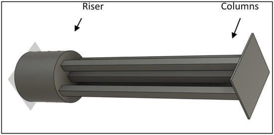
Figure 1.
Sketch showing the columns (samples) connected to the riser: they will be used for performing bending tests.
- Heating up to 250 °C and residence at this temperature for 30 min.
- Heating up to 900 °C and residence at this temperature for 30 min.
- Oven cooling up to 450 °C.
A total of 4 castings were made with 5 columns for each casting. The castings were obtained by induction melting in vacuum from pure Ti, Al, Cr and Nb after six washing cycles with argon. Around 3% vol. of Al2O3 was added to the alloy. Reinforced specimens were produced by adding Al2O3 particles in the crucible. The molten metal was directly cast by using centrifugal casting into a rotating mould. Once the metal solidified, the mould was broken, and the casting was removed mechanically. After extraction, specimens were cut-off from the runner system using a diamond coated cutting blade.
The specimens were then ground and polished to particular dimensions, 2 mm × 4 mm × 45 mm, in order to be tested by four-point bending test at various temperatures, i.e., room temperature, 700 °C, 800 °C, 850 °C, and 900 °C, according to the ASTM C1161 (room temperature) and C1211 (high temperature) [24,25]. The samples were heated at 15 °C/min up to the final temperature, maintained at this temperature for 30 min and then subjected to the flexural test. For each temperature, three samples were tested.
The flexural bending tests were performed with a Zwick-Roell Z 2.5 testing machine (Zwick GmbH, Ulm, Germany) equipped with a Maytec furnace (up to 1600 °C), a 3 point-contact extensometer and a silicon carbide fully articulated flexure device (Maytec GmbH, Singen, Germany). The tests were conducted using a constant crosshead speed of 0.5 mm/min. This value is suggested by the ASTM standards in order to minimise the test time and creep influence. The test duration varied from about 20–200 s (depending on the test temperature and maximum deformation reached during the test), according to the standard recommendations. The elaboration of stress–strain curves allowed the evaluation of Young’s modulus and yield stress. The strain measurement was performed by a properly designed displacement transducer using three alumina rods pushing against the tension face of the sample. The measurement of sample deflection on three separated points allowed to exclude the undesired contribution of thermal expansion of alumina extensometer rods. The described experimental set-up enables a direct and reliable measurement of sample curvature, with appreciable improvements in comparison with the evaluation of crosshead travel or the direct LVDT deflection measurement of the central section of the sample [26,27,28]. Young’s modulus calculation was carried out using a regression of the stress–strain curves between 40 and 80 MPa.
Samples of different castings were ground and polished. In order to perform microstructural examination, they were observed by using optical and electron microscope: the optical microscope was Leica DMI 5000 (Leica, Wetzlar, Germany), while the scanning electron microscope was Tescan Mira3 (Kohoutovice, Czech Republic). This study was performed also to analyse the dispersoid distribution in the metal matrix. X-ray diffraction of the samples was carried out with a Philips X’pert (Malvern, UK) in order to verify the phases in the alloy. The samples were analysed by means of energy dispersion spectroscopy (EDS) to verify the chemical composition and fracture surfaces were inspected by SEM after bending tests (Hitachi S-2500, Krefeld, Germany).
3. Results
Although the different castings had the same nominal composition, there were slight compositional differences after casting. Table 1 shows the average atomic composition of the alloy after casting. It was obtained by performing EDS analyses on several samples.

Table 1.
Mean composition of the tested alloy.
Preliminary tests made to evaluate particle distribution highlighted also that the arrangement of the charge material in the crucible affects the dispersoids distribution and agglomeration. These tests, performed by using 1–3 μm alumina particles, have been important for obtaining a homogeneous distribution. Subsequent castings have been done using 0.04 µm alumina particles. Micrographs of the alloy obtained by performing different castings are reported in Figure 2.
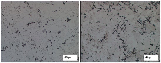
Figure 2.
Optical micrographs showing the particle distribution in different castings.
After selecting the best process parameters, samples of the alloy were cast and analysed. SEM micrographs in Figure 3 and Figure 4 show that the alloy microstructure is constituted by γ phase grains and lamellar grains of alternated γ and α2 phases.
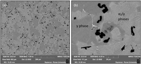
Figure 3.
SEM micrograph showing microstructure of the alloy and dispersion of aggregated microparticles of alumina (a) and a detail of aggregated microparticles (b).
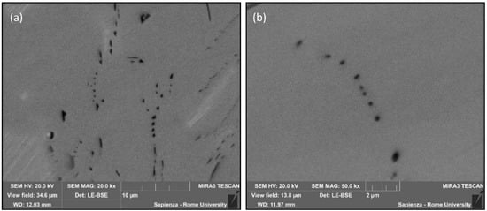
Figure 4.
SEM micrograph showing the dispersion of nanoparticles in the alloy at lower (20,000×) (a) and higher (50,000×) (b) magnification.
The size of the alumina used in the tests was of 0.04 µm, but the microstructural analysis highlights that the particles are partially dispersed as microparticles after agglomeration (Figure 3) and partially dispersed as nanoparticles (Figure 4). The alumina dispersoids are well visible in the SEM micrographs as black particles. EDS analyses carried out on these particles (Figure 5) allowed to identify them. It can be seen that the alumina particles are dispersed both inside γ grains and inside lamellar colonies among the lamellae. Overall, there is a good homogeneity of the alumina particles in the intermetallic matrix. Observing Figure 3, it is apparent that nanoparticles seem to be aligned due to the molten metal flow during centrifugal casting. This confirms that the use of centrifugal casting affects particle distribution and improves the distribution homogeneity of dispersoids. Among different types of dispersoids alumina was selected because its density is quite close to the one of the produced alloys. This is important to avoid particle concentration in one side of the casting. Image analysis carried out on some alloy sections highlighted that as far as the agglomerated particles are concerned, about 65% of them have a size lower than 25 µm2 (Figure 6) and that alumina particle surface is about 2.2% of the surface cover. Figure 3 shows also the presence of a small quantity (about 0.5%) of β phase that appears white in the micrographs.
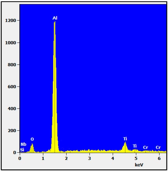
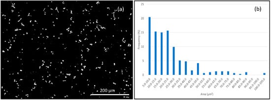
Figure 6.
Image analysis of Al2O3 particles (a), showing particle size distribution throughout the specimens (b).
In order to characterize the alloy microstructure, X-ray diffraction of the samples was carried out in order to identify the different phases in the alloy. The pattern in Figure 7 shows the presence of γ-TiAl and α2-Ti3Al. Moreover, by analysing the pattern the Al2O3 peaks are also visible.
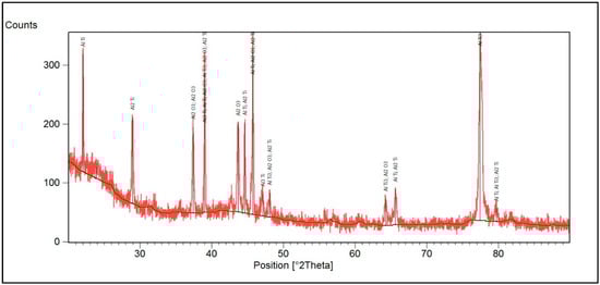
Figure 7.
X ray diffraction pattern of a TiAl sample reinforced by means of alumina particles.
After verifying the composition, the uniform dispersion of alumina and the soundness of the alloy, samples were prepared and subjected to bending tests. Considering that the most interesting applications for TiAl intermetallic alloys are the production of mechanical components working at high temperature, mechanical tests have been performed at room temperature and over the temperature range 700–900 °C. These tests were important for analysing the effect at different temperatures of dispersion strengthening on Young’s modulus and yield stress of the as-cast alloys. Stress-strain curves reported in Figure 8 show the effect of alumina dispersion on the mechanical behaviour of the studied alloy over the temperature range 800–900 °C. Dispersion strengthening is the typical mechanism used for increasing elastic limit, hardness, and creep resistance. In fact, the use of non-shearable particles impedes plastic deformation of the intermetallic matrix. Dispersion strengthening is particularly effective in increasing strength and creep resistance at high homologous temperatures, where other strengthening mechanisms lose their effectiveness. For this reason, in this work it has been analysed to improve the mechanical behaviour of TiAl alloys in extreme conditions for example for gas-turbine application. The curves reported in Figure 8 highlight that alumina dispersion in the intermetallic matrix allows to increase the yield stress and the Young’s modulus of the analysed TiAl alloy in the highest considered temperature range. Figure 9 shows in detail the effect of dispersion strengthening on Young’s modulus: it can be noticed that alumina dispersion increases the Young’s modulus at every considered temperature. This increase that is about 30% in the lower temperature range, reaches about 4% at 900 °C. Thus, the effect of particle dispersion on the Young’s modulus becomes less relevant as far as the temperature increases.
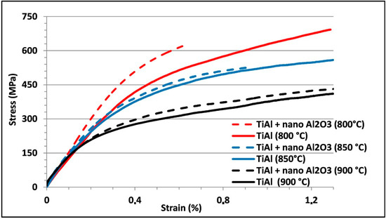
Figure 8.
Stress vs. strain curves obtained from four-point bending tests carried out at different temperatures on specimens with and without alumina dispersoids.
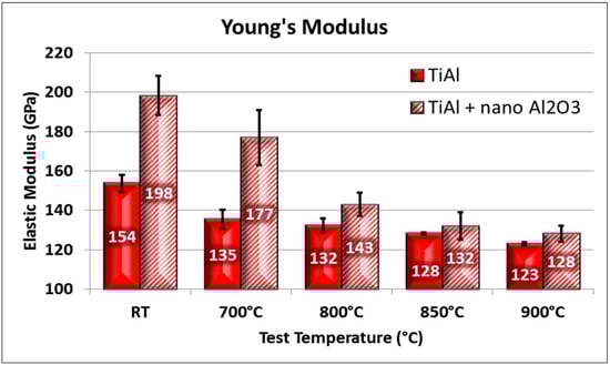
Figure 9.
Elastic modulus vs. temperature gained from four-point bending tests carried out on standard and dispersion strengthened TiAl alloy.
Figure 10 shows the Rp0.1 yield stress as a function of test temperature for both the strengthened and the reference alloy. By analysing the effect of alumina dispersion on the yield stress (Figure 10) it is apparent that the interaction of dislocations with finely dispersed, non shearable and hard oxides produces an increase of the material yield stress at high temperatures. The oxide particles dispersed in the matrix have both nanometric and micrometric size. The reinforcement effects depend on the opposition to the climb mechanism and on the Orowan mechanism. Oxide particles produce a threshold stress that must be overcome to produce dislocation movement. The yield stress increase is about 20% at 800 °C and again becomes less relevant by increasing the temperature. As far as the high-temperature tests are concerned, reference specimens tested at 850 and 900 °C bend during the four-point bending test without reaching the final fracture, while dispersion strengthened alloys reached the final fracture at 850 °C and bend, without fracture, at 900 °C (Figure 11).
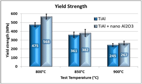
Figure 10.
Yield stress vs. temperature gained from four-point bending tests carried out on standard and dispersion strengthened TiAl alloy.
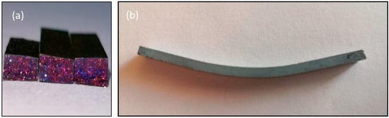
Figure 11.
Macrograph showing the fracture surfaces at 850 °C (a) and the plastic deformation at 900 °C (b) of specimens tested by the four-point bending test.
Plastic deformation of the studied alloy at high temperature is enhanced by the presence of glide and twinning systems in γ phase grains. Despite that, the presence of dispersoids, which hinders dislocation movement, decreases the alloy plasticity even at 850 °C. SEM analyses carried out on fracture surfaces showed that the fracture propagates following a transgranular path at all the tested temperatures. It can also be stressed that inside the lamellar colonies the fracture propagates with a mixed mechanism that produces both translamellar and interlamellar fracture. A careful observation of micrographs in Figure 12 reveals that fracture is very brittle with translamellar (Figure 12a) and interlamellar (Figure 12b) propagation areas. Figure 13a shows a typical interlamellar fracture at 700 °C, while at 800 °C a slightly more plastic behaviour can be noticed (Figure 13b). At 850 °C the brittle fracture surface shows blunt edges and small areas characterised by plastic deformation (Figure 14). Fracture surface observation did not highlight a relevant effect of alumina particles on the fracture path. As described in a previous paper, the selected reference alloy is characterized by a relatively high fracture toughness: Its value has been found to be 22 MPa√m [14]. Both reference and strengthened alloys increase their plasticity by increasing the temperature, but in the lower temperature range they have a very brittle behaviour and thus they are very susceptible to fracture in the presence of discontinuities such as microshrinkage cavities. Specimens used for bending tests have been produced directly by centrifugal casting and, considering that they have high surface/volume ratio, several process parameters have been modified in order to reduce their tendency to form shrinkage defects and to obtain defect-free samples. Despite that, by observing the fracture surfaces it is possible to find on some of them shrinkage defects that are well visible in Figure 15a. It is interesting to observe that dendrites grown inside shrinkage cavities have a lamellar structure (Figure 15b).
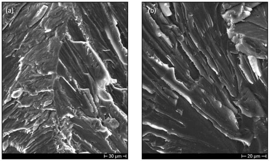
Figure 12.
SEM micrographs showing the fracture surfaces of samples tested at room temperature. Translamellar (a) and interlamellar (b) fracture propagation can be noticed.
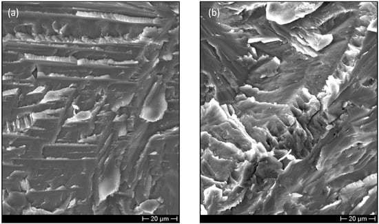
Figure 13.
SEM micrographs showing the fracture surface at 700 °C (a) and at 800 °C (b).
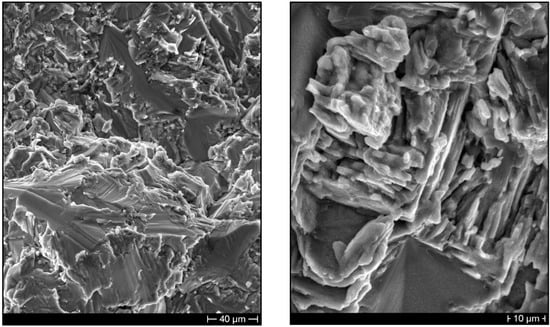
Figure 14.
SEM micrographs showing the fracture surface at 850 °C.
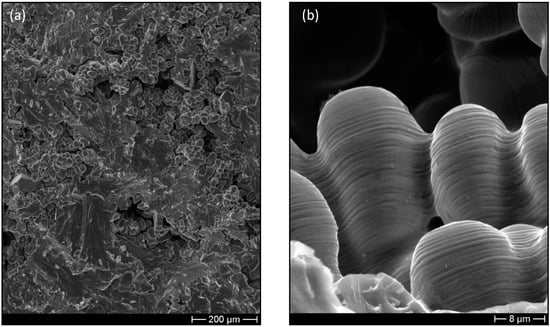
Figure 15.
SEM micrograph showing shrinkage cavities on the fracture surface of a sample tested at room temperature (a) and lamellar structure of dendrites in the shrinkage cavity (b).
4. Conclusions
The research carried out in this paper showed that it is possible to obtain a homogeneous dispersion of nanoparticles of Al2O3 in a γTiAl intermetallic alloy directly by centrifugal casting.
The mechanical tests highlighted that the dispersion of Al2O3 particles improves the mechanical properties of the selected alloy at each considered temperature. In particular, this allows to considerably increase the Young’s modulus that in the lower temperature range is 30% higher than that of the reference alloy. The analysis of the yield stress over the temperature range 800–900 °C pointed out that dispersion strengthening affects the yield stress by increasing its value of about 20% even at 800 °C. The obtained results showed that Al2O3 dispersion strengthening of TiAl intermetallic alloys by using centrifugal casting allows to further increase their specific mechanical properties at high temperature, thus further widening their application fields.
Author Contributions
D.P. and F.F. designed the study. A.B. and A.M. performed the castings and the specimen analyses. G.P., F.M. and L.P. performed mechanical tests and elaborated the obtained data. A.M. carried out image analysis on several micrographs of the alloys. D.P. and F.F. wrote the paper and revised the manuscript during the revision process. All authors have read and agreed to the published version of the manuscript.
Funding
This research received no external funding.
Conflicts of Interest
The authors declare no conflict of interest.
References
- Clemens, H.; Smarsly, W. Light-weight intermetallic titanium aluminides—Status of research and development. Adv. Mater. Res. 2011, 278, 551–556. [Google Scholar] [CrossRef]
- Kim, Y.W. Gamma titanium aluminides: Their status and future. JOM 1995, 47, 39–42. [Google Scholar] [CrossRef]
- Appel, F.; Brossmann, U.; Christoph, U.; Eggert, S.; Janschek, P.; Lorenz, U.; Müllauer, J.; Oehring, M.; Paul, J.D.H. Recent progress in the development of gamma titanium aluminide alloys. Adv. Eng. Mater. 2000, 2, 699–720. [Google Scholar] [CrossRef]
- Clemens, H.; Mayer, S. Intermetallic titanium aluminides in aerospace applications—Processing, microstructure and properties. Mater. High Temp. 2016, 33, 560–570. [Google Scholar] [CrossRef]
- Bewlay, B.P.; Nag, S.; Suzuki, A.; Weimer, M.J. TiAl alloys in commercial aircraft engines. Mater. High Temp. 2016, 33, 549–559. [Google Scholar] [CrossRef]
- Tetsui, T. Development of a second generation TiAl turbocharger. Mater. Sci. Forum 2007, 561–565, 379–382. [Google Scholar] [CrossRef]
- Noda, T. Application of cast gamma TiAl for automobiles. Intermetallics 1998, 6, 709–713. [Google Scholar] [CrossRef]
- Keller, M.M.; Jones, P.E.; Porter, W.J.; Eylon, D. The development of low-cost TiAl automotive valves. JOM 1997, 49, 42–44. [Google Scholar] [CrossRef]
- Liu, K.; Ma, Y.C.; Gao, M.; Rao, G.B.; Li, Y.Y.; Wei, K.; Wu, X.; Loretto, M.H. Single step centrifugal casting TiAl automotive valves. Intermetallics 2005, 13, 925–928. [Google Scholar] [CrossRef]
- Kothari, K.; Radhakrishnan, R.; Wereley, N.M. Advances in gamma titanium aluminides and their manufacturing techniques. Prog. Aerosp. Sci. 2012, 55, 1–16. [Google Scholar] [CrossRef]
- Sauthoff, G. Intermetallics; VCH (Ed.): Weinheim, Germany, 1995. [Google Scholar]
- Brotzu, A.; Felli, F.; Pilone, D. Fracture toughness of TiAl-Cr-Nb-Mo alloys produced via centrifugal casting. Frat. Integrita Strutt. 2012, 22, 20–25. [Google Scholar] [CrossRef]
- Brotzu, A.; Felli, F.; Marra, F.; Pilone, D.; Pulci, G. Mechanical properties of a TiAl-based alloy at room and high temperatures. Mater. Sci. Technol. 2018, 34, 1847–1853. [Google Scholar] [CrossRef]
- Brotzu, A.; Felli, F.; Pilone, D. Effect of alloying elements on the behaviour of TiAl-based alloys. Intermetallics 2014, 54, 176–180. [Google Scholar] [CrossRef]
- Brotzu, A.; Felli, F.; Pilone, D. Effects of the manufacturing process on fracture behaviour of cast TiAl intermetallic alloys. Frat. Integrita Strutt. 2014, 8, 66–73. [Google Scholar] [CrossRef]
- Kubena, I.; Fournier, B.; Kruml, T. Effect of microstructure on low cycle fatigue properties of ODS steels. J. Nucl. Mater. 2012, 424, 101–108. [Google Scholar] [CrossRef]
- Wang, J.; Yuan, W.; Mishra, R.S.; Charit, I. Microstructure and mechanical properties of friction stir welded oxide dispersion strengthened alloy. J. Nucl. Mater. 2013, 432, 274–280. [Google Scholar] [CrossRef]
- Koch, C.C.; Whittenberger, J.D. Mechanical milling/alloying of intermetallics. Intermetallics 1996, 4, 339–355. [Google Scholar] [CrossRef]
- Benjamin, J.S. Dispersion strengthened superalloys by mechanical alloying. Metall. Trans. 1970, 1, 2943–2951. [Google Scholar] [CrossRef]
- Rittinghaus, S.-K.; Wilms, M.B. Oxide dispersion strengthening of gamma TiAl by laser additive manufacturing. J. Alloys Compd. 2019, 804, 4. [Google Scholar] [CrossRef]
- Ai, T. Microstructure and mechanical properties of in-situ synthesized Al 2O3/TiAl composites. Chin. J. Aeronaut. 2008. [Google Scholar] [CrossRef]
- Lu, X.; Li, J.; Chen, X.; Qiu, J.; Wang, Y.; Liu, B.; Liu, Y.; Rashad, M.; Pan, F. Mechanical, tribological and electrochemical corrosion properties of in-situ synthesized Al2O3/TiAl composites. Intermetallics 2020, 120, 106758. [Google Scholar] [CrossRef]
- Kenel, C.; Lis, A.; Dawson, K.; Stiefel, M.; Pecnik, C.; Barras, J.; Colella, A.; Hauser, C.; Tatlock, G.J.; Leinenbach, C.; et al. Mechanical performance and oxidation resistance of an ODS γ-TiAl alloy processed by spark plasma sintering and laser additive manufacturing. Intermetallics 2017, 91, 169–180. [Google Scholar] [CrossRef]
- ASTM C1161-13. Standard Test Method for Flexural Strength of Advanced Ceramics at Ambient Temperatures; ASTM International: West Conshohocken, PA, USA, 2013. [Google Scholar]
- ASTM C1211-13. Standard Test Method for Flexural Strength of Advanced Ceramics at Elevated Temperatures; ASTM International: West Conshohocken, PA, USA, 2013. [Google Scholar]
- Pulci, G.; Tului, M.; Tirillò, J.; Marra, F.; Lionetti, S.; Valente, T. High temperature mechanical behavior of UHTC coatings for thermal protection of re-entry vehicles. J. Therm. Spray Technol. 2011, 20, 139–144. [Google Scholar] [CrossRef]
- Baiamonte, L.; Marra, F.; Pulci, G.; Tirillò, J.; Sarasini, F.; Bartuli, C.; Valente, T. High temperature mechanical characterization of plasma-sprayed zirconia-yttria from conventional and nanostructured powders. Surf. Coat. Technol. 2015, 277, 289–298. [Google Scholar] [CrossRef]
- Di Girolamo, G.; Marra, F.; Blasi, C.; Schioppa, M.; Pulci, G.; Serra, E.; Valente, T. High-temperature mechanical behavior of plasma sprayed lanthanum zirconate coatings. Ceram. Int. 2014. [Google Scholar] [CrossRef]
Publisher’s Note: MDPI stays neutral with regard to jurisdictional claims in published maps and institutional affiliations. |
© 2020 by the authors. Licensee MDPI, Basel, Switzerland. This article is an open access article distributed under the terms and conditions of the Creative Commons Attribution (CC BY) license (http://creativecommons.org/licenses/by/4.0/).