Article

Numerical and Experimental Investigation of Controlled Weld Pool Displacement by Electromagnetic Forces for Joining Dissimilar Materials

by
Jennifer Heßmann
1,2,*,
Marcel Bachmann
1 and
Kai Hilgenberg
1,2
1
Bundesanstalt für Materialforschung und-prüfung (BAM), Unter den Eichen 87, 12205 Berlin, Germany
2
Institute of Machine Tools and Factory Management, Technical University Berlin, Pascalstraße 8-9, 10587 Berlin, Germany
*
Author to whom correspondence should be addressed.
Metals 2020, 10(11), 1447; https://doi.org/10.3390/met10111447
Submission received: 25 September 2020 / Revised: 21 October 2020 / Accepted: 27 October 2020 / Published: 29 October 2020
(This article belongs to the Special Issue Dissimilar Material Welding and Joining)

Abstract

:
In order to reduce CO2 emissions, an increasing interest in lightweight construction exists in the automotive industry, especially the multi-material-design approach. The main construction materials here are steels and aluminium alloys. Due to their different physical material properties and limited mutual solubility, these two materials cannot be joined thermally without difficulty. This paper presents a new joining approach for dissimilar materials. It uses electromagnetic displacement of a laser-generated melt pool to produce overlap joints between 1 mm steel (1.0330) and 2 mm aluminium alloy (EN AW 5754). Contactless induced Lorentz forces are generated by an alternating current (AC) magnet system. The controlled displacement of the aluminium alloy melt into the hole of the overlying steel sheet is investigated through numerical and experimental studies. The numerical results are compared with cross sections and thermocouple measurements. For the first time, it is possible to achieve a reproducible controlled melt pool displacement on thin sheets to produce overlap joints between dissimilar materials.

1. Introduction

In the last few years, the use of lightweight materials, such as aluminium, has increased continuously in the automotive industry [1]. This has resulted from strict emission regulations to reduce CO2 emissions. A possible solution for this challenge is to reduce the weight of the car, which has resulted in a growing interest in lightweight construction. In the overview work of Hirsch [2], it becomes clear that a multimaterial design that combines different materials to create function- and weight-optimized structures is being used more and more for automotive applications. Laser beam welding is being established in a wide range of applications. In addition to the automotive industry, laser beam welding is also applied for joining different aluminium alloys for the manufacture of airframes [3]. Through laser beam modifications, laser beam welding allows further production possibilities. By using an interlayer and a pulsed laser beam, different combinations of dissimilar materials, such as titanium and steel [4], can be joined as butt joints [5]. A comparison between steel and aluminium alloy applications in the automotive industry is given in [6]. They point out that to produce lightweight car bodies, the most important construction materials are high strength-steels and high-strength aluminium alloys. An overview of laser welding between aluminium alloys and steels is given in [7]. The authors show that the development of durable joints between dissimilar materials is still a challenge to overcome. For thermal joining processes, problems are caused by the different electrical, thermal, and mechanical properties of these materials. In addition, steel and aluminium alloys are not dissolvable in the solid state. This leads to the formation of brittle intermetallic phases. Therefore, joining processes without melting both materials are currently used in industrial applications. These include adhesive bonding, mechanical joining and their combinations, and resistance element welding. Adhesive joints reach an adequate strength only with large joining surfaces. The surfaces to be joined have to be carefully prepared, and the workpieces cannot be further processed while the adhesive is hardening [8]. One of the mechanical joining processes is riveting. Additional auxiliary joining elements are needed, which have to be inserted into the components to be joined by deformation forces. This can lead to a decrease in strength, since the deformation process could damage the surrounding material [9]. The additional auxiliary joining elements are expensive, and the additional weight due to the high number of necessary connection points in automobile construction affects the lightweight construction balance. Resistance element welding also requires auxiliary joining elements so that the same disadvantages occur as in riveting. Therefore, the development of new joining techniques for lightweight construction is essential.
It would be advantageous to develop a thermal joining technology that does not require any auxiliary joining elements or filler materials, whereby only one joining partner is melted to limit the formation of intermetallic phases. To realize a joint, this generated melt has to be moved in a controlled way by forces into a hole or longitudinal groove of the second joining partner. Metallic melts can be influenced by Lorentz forces. The influence of the melt by electromagnetic forces has already been demonstrated for various possible applications. Among other things, the generation of electromagnetic forces by an oscillating magnetic field in the weld pool improves the degassing process when welding 6 mm thick aluminium die castings (AC-AlSi9MnMg). The porosity could be reduced by up to 75% [10]. Since the influence of electromagnetic forces in the melt pool is difficult to observe, FE simulations provide a better understanding of the electromagnetic force effects. Numerical analyses already exist for thick sheets. The effect of electromagnetic forces as melt pool support during the welding of 20 mm thick AlMg3 alloy sheets was analyzed using a three-dimensional laminar and stationary numerical model [11]. The simulation results were compared with welding experiments. The dropout could be successfully reduced by using an AC magnetic system below the weld seam. The generation of electromagnetic forces into the weld seam helps to compensate the hydrostatic pressure in the melt pool. The electromagnetic forces are directed against the hydrostatic pressure. The application of electromagnetic forces as melt pool support when welding 20 mm thick AISI 304 stainless steel sheets using a three-dimensional turbulent stationary numerical model is demonstrated in [12]. The simulation results were also compared with those of welding experiments. It could be shown that even when welding paramagnetic stainless steel, the generation of electromagnetic forces by an alternating current magnetic field reduces the dropout during welding. These findings demonstrate possible applications of electromagnetic forces in thick sheet welding. So far, no investigations of electromagnetic forces on thin sheets to join dissimilar materials have been carried out.
This paper presents a new joining technology for dissimilar metal materials based on a melt pool displacement by electromagnetic forces and resulting firmly bonded joint in an overlap arrangement. The melt pool displacement is generated by contactless induced Lorentz forces by an AC magnet system. The aim of this paper is to demonstrate a controlled displacement of the melt at thin sheets for spot joints. The focus lies on verifying whether this controlled displacement is possible to fill up a hole in a layer of sheet metal and how long such a displacement would take. The necessary process time is highly relevant for a possible industrial application. Therefore, numerical and experimental studies are performed to identify the process parameters that influence the displacement. In addition, this study will verify whether the displacement process is stable and reproducible. The numerical analyses are compared with those of weld experiments and thermocouple measurements to verify the numerical temperature profile in the steel sheet. Cross sections of the welding samples are used to compare the numerical melt pool contours.

2. Theoretical Background

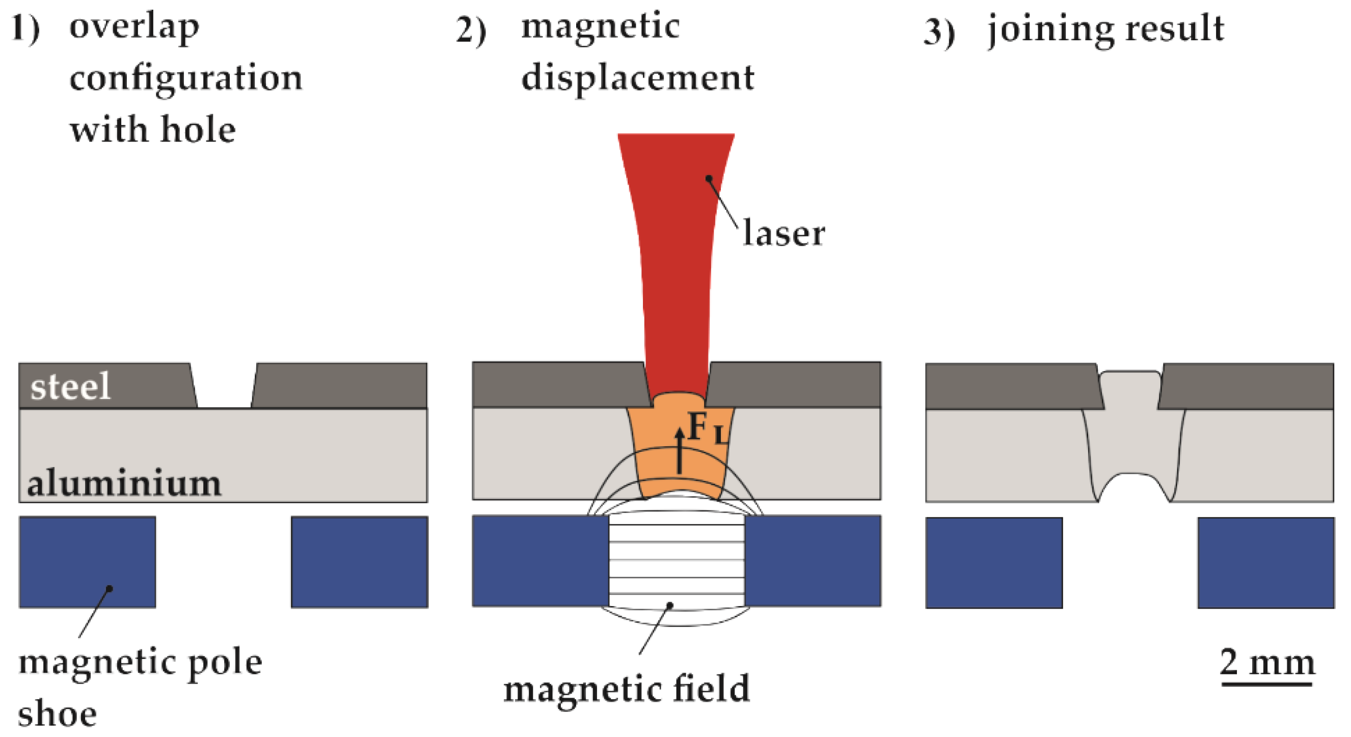
2.1. Concept of a Novel Joining Technology

The combination of laser beam-induced melt pool and electromagnetic forces can be used to produce a form and firmly bonded joint between dissimilar materials. This joining method is usable for overlap joints, spot and line joints. This novel joining technology needs no auxiliary elements or filler materials and works without contact. The individual process steps of this joining technology are explained below and illustrated in Figure 1.
In an overlap joint between dissimilar materials, the upper joining partner must have a higher melting temperature and the lower joining partner a lower melting temperature. A hole or longitudinal groove is drilled or stamped in the upper joining partner (1) so that the laser beam can melt the joining partner underneath through the hole or longitudinal groove (2). The melting of the upper joining partner has to be avoided so that the formation of intermetallic phases is reduced. The Lorentz forces are induced into the melt pool without contact and displace the melt upwards while the laser is still on power. The displaced melt solidifies in the hole, resulting in a form and material bonded joint (3). The contraction stresses resulting from cooling down could cause an additional compression of the joining partners.

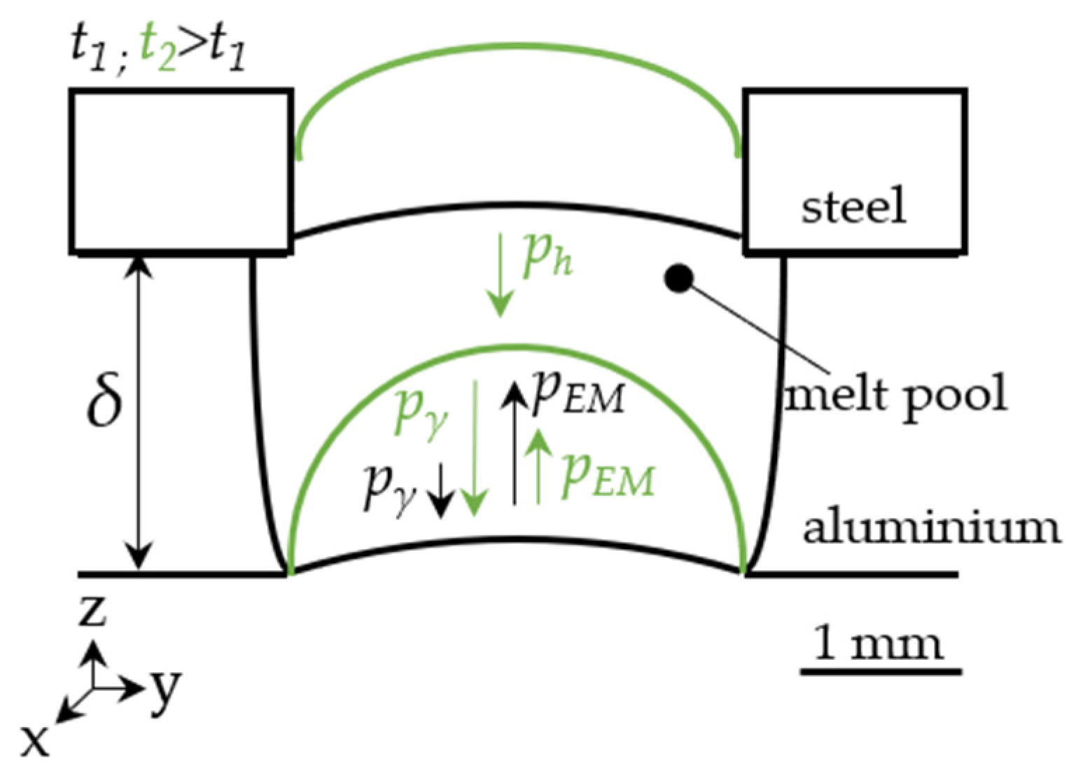
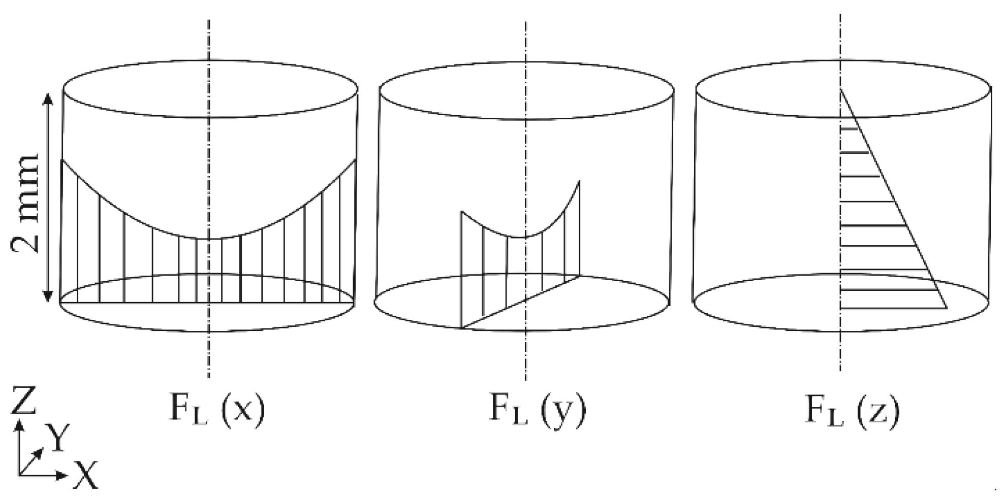
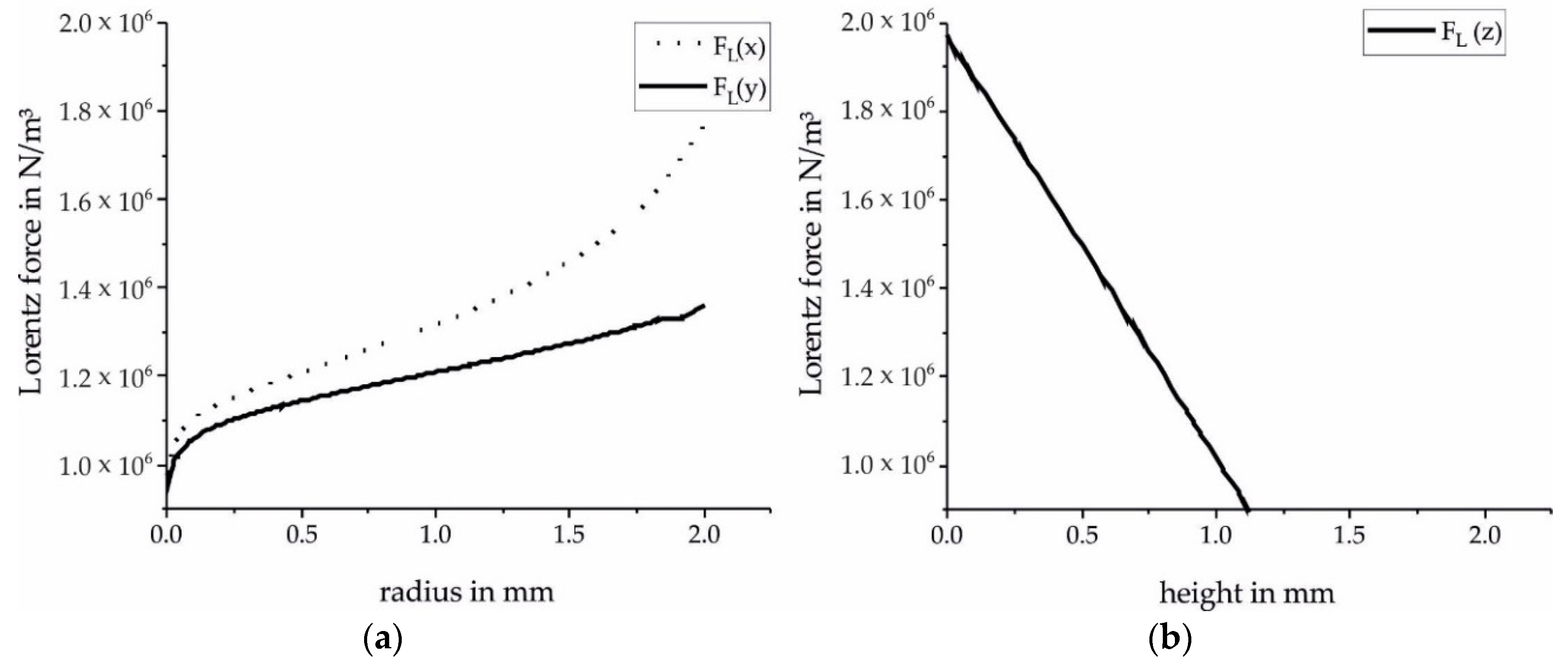
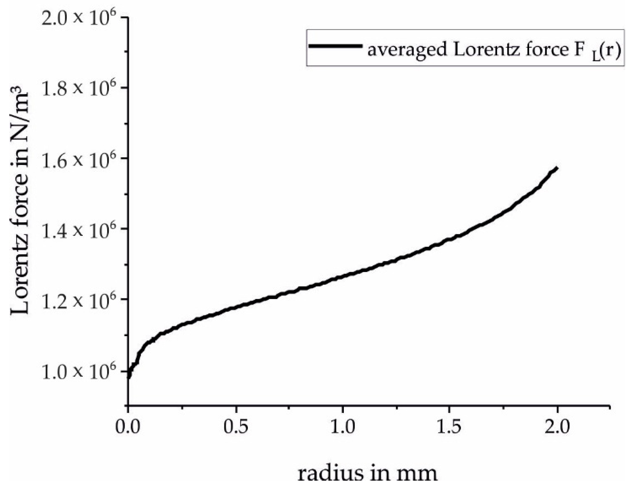
2.2. The Generation and Development of Electromagnetic Forces for the Displacement of the Melt

The controlled displacement of the melt is shown schematically in Figure 2. For the generation of electromagnetic forces, an oscillating magnet system is placed below the overlap configuration of thin steel and aluminium alloy sheets. The magnetic pole (MP) shoes are placed next to the melt pool on the left and right sides. Between the magnetic pole shoes, a magnetic field B oscillates and induces an eddy current j vertically orientated to the oscillating magnetic field. Lorentz forces FL are generated by the cross product of the magnetic field and the eddy current:
F L   =   j   ×   B
Without contact, the Lorentz forces are induced into the aluminium alloy sheet and generate an electromagnetic pressure pEM, which is oriented against gravity. The electromagnetic pressure can be described with µ0 as the magnetic field constant (4π × 10−7 H m −1):
p E M =   B 2 2 μ 0
The effective range of the electromagnetic forces is determined by the frequency. It is characterized by the thickness of the skin layer δ with σ as the electrical conductivity of the aluminium alloy melt:
δ = ( π f σ μ 0 )   1 / 2
The skin layer thickness is inversely proportional to the alternating frequency f of the magnetic field. Therefore, the electromagnetic pressure can be limited to the aluminium alloy sheet.
Different pressures exist in the melt pool, the hydrostatic pressure ph, the electromagnetic pressure pEM, the Laplace pressure pγ, the hydrodynamic pressure pd, and the ablation pressure pr. During the displacement process, the pressure conditions in the melt pool change. For simplification, ablation pressure and hydrodynamic pressure are not considered and are only listed for completeness. The hydrostatic pressure stays constant since the height of the molten pool column does not change during the displacement. The hydrostatic pressure acts downwards to the bottom of the melt pool. During the displacement, the melt leaves the effective range of the electromagnetic field, and so the electromagnetic pressure decreases during the displacement process. The Laplace pressure grows with increasing curvature of the displaced melt pool surface. The Laplace pressure acts as the hydrostatic pressure downwards to the bottom of the melt pool, while the electromagnetic pressure acts upwards. The development of the different pressures during the displacement is illustrated schematically in Figure 3 at two points in time.

3. Materials and Setups

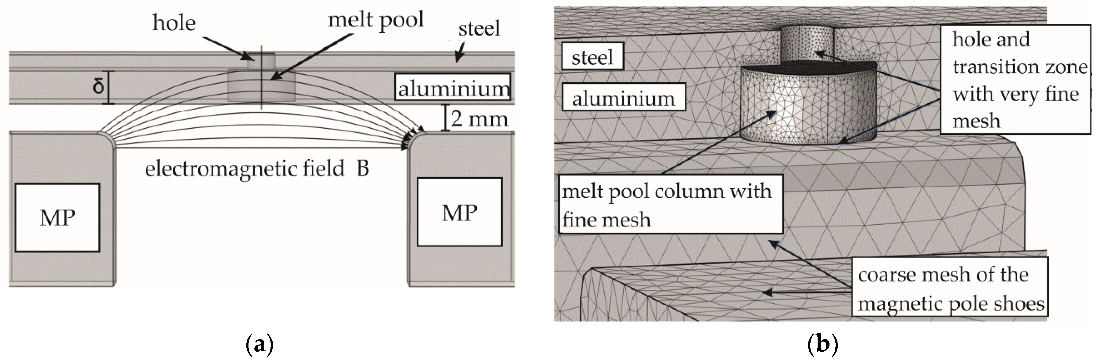
3.1. Numerical Setup

A finite element solver by COMSOL Multiphysics GmbH, Berlin, Germany (versions 4.3 and 5.4) was used to perform the numerical investigation. For the simulation, an overlap joint of a steel sheet with a thickness of 1 mm and an aluminium wrought alloy with a thickness of 2 mm for spot joint was modelled. A hole with a diameter of 1.6 mm was provided in the steel sheet. The dimensions of the hole were generated on the basis of pretests for melt pool generation. The hole was selected in such a way that one-third of the melt pool volume generated by the laser beam was sufficient to fill the hole.
Two independent models were designed: a three-dimensional model for generating the Lorentz force distribution in the melt pool and a two-dimensional rotationally symmetric model for the displacement process and the temperature distribution in the joining partners. The qualitative three-dimensional distribution of the Lorentz forces in a 2 mm aluminium alloy sheet is shown schematically in Figure 4.
Furthermore, the effective range of the Lorentz forces in all numerical experiments is limited to the thickness of the aluminium sheet. This requires a high frequency of 3750 Hz, according to the definition of skin thickness. This high frequency would significantly increase the computing time of a process simulation. For this reason, the resulting mean Lorentz force was used in the two-dimensional process simulation. The magnetic pole shoes are located below the overlap joint at a distance of 2 mm. The magnetic pole shoes are 17.5 mm apart and have a cross section of 19 mm × 19 mm. The three-dimensional model is shown in Figure 5a. The transient melt pool development and transient temperature development between the metal sheets are not considered in the three-dimensional model. The focus lies on the generation of the distribution of the Lorentz forces. A defined melt pool column is modelled in the aluminium alloy sheet in which the current density of the oscillating magnet system is induced. The diameter of the melt pool column is 4 mm and originates from preliminary tests concerning melt pool generation. The edge of the melt pool column was set to the melting temperature of the aluminium alloy. In the middle of the melt pool column, the evaporation temperature of the aluminium alloy is implemented for simplification as this is the area where a keyhole would occur. The domains of the melt pool column, the hole, and the surrounding region were meshed with varying degrees of element sizes. In the region of the melt pool column, the mesh has a maximum element size of 0.09 mm and total of 73,766 elements. The large meshed area has a maximum element size of 1.2 mm and 123,323 elements. The Lorentz forces were simulated for five different magnetic field strengths at a constant frequency of 3750 Hz. The different meshed regions of the three-dimensional model are given in Figure 5b.
In the rotationally symmetric second numerical model, the fluid dynamics and the heat transfer between the different metal sheets and air are considered. This model has a similar structure as the three-dimensional model, but in contrast, the material properties depend on the temperature. The phase-field method was used for the transition between liquid aluminium alloy and air. The transition from fine-meshed regions to coarse-meshed regions is continuous. The smallest element size is 0.006 mm in the area of the hole and the aluminium alloy melt pool as well as at the boundary layer between the steel and aluminium alloy sheet. This results in a total of 331,070 elements.
For the two independent simulation models, material models were selected that came closest to the metal materials used in the experiments. The thermophysical properties of the metal materials up to evaporation temperature were taken from the literature. Table 1 and Figure 6 give an overview of the material properties used in this study. The flow in the air is not important for this work and has no influence on the results of the investigation. Therefore, the air is modelled in a simplified way as a laminar and incompressible fluid according to the work of Bruyere et al. [13]. For this, the air density was divided by the factor 10, and the dynamic viscosity was multiplied by the factor 50. This procedure has no influence on the physical effects on the aluminium alloy melt pool. The properties of air at room temperature are listed in Table 2.
Volume heat sources are used for deep-penetration welding. The heat source used in this study was modified based on the heat source from the work of Lu et al. for our case as follows [18]:
Q =   9 P π R 0 2 H   ( 1 e p s 3 ) exp [ 9 r 2 R 0 2 log ( H z ) ]   ·   R L ( t )
The first term describes the laser energy density depending on the laser power P with a beam radius R0 and a heat source depth H. The constant eps is an internal COMSOL constant that is a very small number in the order of 10−15 to avoid division by zero. The second term defines the intensity distribution depending on the coordinates r and z. The Gaussian intensity distribution is defined at any z coordinate. The intensity distribution is limited by the exponential function. The heat source model is shown schematically in Figure 7. The absorption coefficient was set to 100%. The laser beam radius R0 was taken from a previously performed caustic measurement. The depth H was calibrated in pretests for melt pool generation on aluminium alloy sheets. This resulted in a value of 8 mm for H. The laser shape function is RL(t). It defines the beam duration and the switch-off behavior of the laser. At 0 ms, the laser is already at 100% power. The beam duration at 100% was 200 ms. After 200 ms, the laser was ramped down in 30 ms. During the displacement process, the upper and lower sides of the aluminium melt pool move in the z-direction upwards. The heat source is coupled to the top and bottom of the melt pool and moves synchronously with the z-direction upwards.
For fluid dynamic observations, the Navier–Stokes equations for laminar and incompressible flows are used. The momentum equation is
ϱ   δ u δ t   +   ϱ   ( u · u ) =   · p I +   μ   ( u + ( u ) T ) +   ϱ g + F
with the density ρ, flow velocity u, physical pressure p, viscosity μ, and source term F. For the source term, the electromagnetic volume forces are used since no other forces are considered.
The following formula applies to mass preservation:
·   ϱ u =   0
For the conservation of energy:
ϱ   C p   δ T δ t +   ϱ   C p     u   ·   T =     · ( k T ) + Q
with Cp as the specific heat capacity, k the thermal conductivity, and Q the source term. In this case, the source term describes the energy supplied by the laser beam according to Formula (4). The used process parameters of the two-dimensional model are listed in Table 3.
The simulations of the second model are limited by the following assumptions and boundary conditions:
  • The flows in the aluminium alloy melt and in the air are assumed to be laminar and incompressible Newtonian flows.
  • The formation of a keyhole is not considered.
  • In this analysis, spot welds are performed so that a flow around the capillary due to a welding speed is not present. Thus, the simulation of the displacement process can be carried out two-dimensionally and rotationally symmetrically.
  • The flows in the aluminium alloy melt pool are only initiated by the Lorentz forces introduced. No Marangoni convection, free convection, vapor friction, and recoil forces of the keyhole are considered.
  • Based on thermocouple measurements, it is known that a magnet power of 2.8 kW results in a maximum inductive heating of 35 °C after 10 s. This low inductive heating is not included in the simulations.
  • In reality, there is no ideal contact surface between steel and aluminium alloy sheets due to surface roughness. An air gap of 0.5 mm between the sheets is modelled to take this physical effect into account.
  • The Lorentz forces are constantly induced into the melt pool. They are not formed or switched off by a function in time dependence FL = FL (melt).
  • The laser power is controlled by a time function. The laser has 100% power at the beginning of the simulation and is shut down after 200 ms with a linear ramp with 30 ms length.
  • A fixed temperature of 273 K was defined on the outer edge of the aluminium alloy sheet.
  • The metal material properties are temperature dependent up to the evaporation temperature.
  • When the melt is displaced into the hole, the contact angle between the hole wall and the melt pool surface changes depending on the curvature of the melt pool surface. This effect is considered.

3.2. Experimental Setup

The self-constructed AC magnet system is placed 2 mm below the overlap joint. It consists of two primary coils, four secondary coils, a capacitor, a double-U-shaped iron core, and two magnetic pole shoes. The secondary coils close to the magnetic pole shoes are connected in series and consist of 20 copper tape turns. The primary coils consist of copper wire with a total of 17 turns. The integrated capacitator and the secondary coils form an LC resonant circuit. The dimensions of the magnetic pole shoes and the distance between the magnetic pole shoes are the same as in the numerical model. This oscillation circuit is calibrated at room temperature as in the study of Fritzsche et al. [19]. The design of the AC magnet system is shown schematically in Figure 8. The oscillating circuit has to be operated at a resonant frequency for optimum efficiency. Then there is no phase shift between voltage and current, and the resistances of capacitance and inductance are neutralized. The resonant frequency of the magnet system used was 3750 Hz. The resonance frequency also determines the penetration depth of the magnetic field already described. At this frequency, the penetration depth of the magnetic field was 4 mm.
A solid-state laser from IPG Laser GmbH, Burbach, Germany (type 20 kW ytterbium fiber laser) was used for the welding experiments. The laser beam was not tilted towards the sample surface and was focused on the surface of the lower joining partner. An inert gas nozzle was placed at an angle of 60° next to the laser beam to protect the weld pool from the atmosphere. Argon with 20 l min−1 was used as inert gas. An optimization of the melt pool expansion by using a different inert gas was not found. The shielding gas flow rate was chosen to ensure that enough shielding gas was available to protect the melt pool. A higher protective gas flow rate would influence the displacement process. The AC magnet system and the laser are stationary.
The lower joining partner is a 2 mm thick aluminium wrought alloy (EN AW 5754), and the upper joining partner is a 1 mm thick steel (1.0330). The hole in the steel sheet has a diameter of 1.6 mm. The experimental setup is shown schematically in Figure 9. The surfaces are cleaned with ethanol before welding. The spot joints were performed at 2.5 kW, 200 ms, and different magnetic field powers from 73 to 1936 W. The magnetic field power was the only process parameter that was varied. The welding parameters are listed in Table 4. Each parameter set was repeated four times. Therefore, a total of 25 spot joints were carried out. A waiting time was used after each parameter set in order to reduce the heating of the plates. This ensured a similar starting situation for each parameter set. Five additional spot joints were carried out without the magnet system to evaluate the influence of the magnet system.
The joining process was monitored with a high-speed camera of Fastcam Inc., Chicago, IL, USA (type SA4) and three thermocouples for each spot joint. The thermocouples (type K) were fixed manually at a distance of 50 µm to the edge of the hole on the top side of the steel sheet. The distance of the thermocouples to the edge of the hole was measured with a stereo microscope. The recording rate was 600 Hz. The experimental thermocouple measurements were compared with the numerical temperature profile in the steel sheet corresponding to the measuring location in the experiment. The analysis of the melt pool contours was carried out in cross sections (etching: 2% nital and 2% NaOH). The cross sections were placed in the middle of the spot joint. To check the size of the intermetallic phases, an etched sample was exemplarily analyzed by scanning electron microscopy of Thermo Fisher Scientific, Berlin, Germany (type Phenom XL).

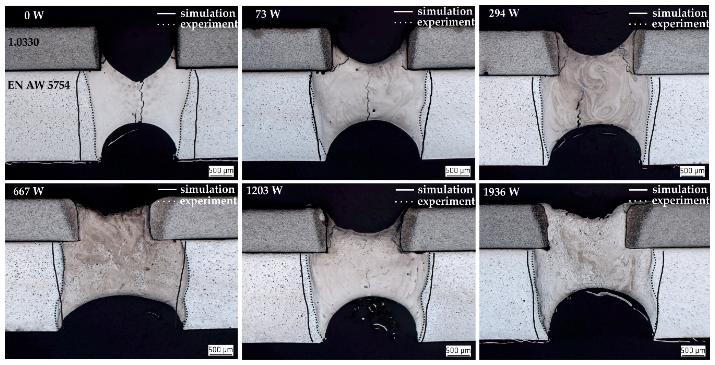
4. Results and Discussion

The numerical results for the three-dimensional distribution of the Lorentz forces are shown to be exemplary for 1936 W in Figure 10. The distribution of the Lorentz forces from the simulation model corresponds to the estimated distribution in Section 3.1.
The Lorentz forces in the x- and y-directions in Figure 10a differ by less than 10% from 0 mm up to 0.8 mm, which is the area where a displacement of melt takes place. This allows for generating an averaged Lorentz force distribution from the x- and y-directions as a simplification for the second two-dimensional model, and for applying it rotationally symmetrically. The generation of the averaged Lorentz force FL(r) is shown as an example of the strongest magnetic field (1936 W) in Figure 11. The Lorentz forces in the z-direction in Figure 10b reach their maximum at the bottom of the aluminium alloy sheet. The Lorentz forces decrease with increasing height (z-axis) due to the skin effect.
Figure 12 shows the numerical results of melt pool development at magnetic field powers from 0 to 1936 W for the time steps 100 ms Figure 12a and 200 ms Figure 12b. The reference case without the influence of the electromagnetic forces (0 W) is also shown. A uniformly shaped melt pool is created without upward displacement in the reference case. Without electromagnetic forces, the lower edges of the holes in the steel sheet reach a temperature of about 1000 K. With increasing electromagnetic power (73 to 1936 W), the molten aluminium alloy is increasingly and rapidly displaced into the hole in the steel sheet. At low electromagnetic powers, only the lower inner edge of the hole heats up at first. Due to the higher electromagnetic power and the rapid displacement of the molten aluminium in the hole, the inner edge of the hole heats up more intensely, as well as over the whole thickness of the steel sheet. With increasing electromagnetic power, the aluminium alloy melt is displaced faster and remains in the hole for a longer time until solidification. This increases the heat-affected area in the steel layer at the inner hole edge.
The height of the displacement of the aluminium alloy melt is limited. The numerical results show that a reproducible equilibrium state is reached in the melt pool between the applied forces. The displacement process is completed earlier with increasing electromagnetic power. Compared with 73 W, where the magnetic field power is not strong enough for complete displacement up to 200 ms, the displacement process is completed after 100 ms for 1936 W.
The shape of the melts changes due to the influence of the electromagnetic forces. The melt pool becomes wider on the top side of the aluminium alloy sheet. The development of the melt pool flows induced by the Lorentz forces for 1936 W from 50 to 200 ms is exemplarily shown in Figure 13.
The wide melt pool top side results from the changing convective heat transfer during the displacement process. Within the hole, the heat dissipation is reduced because steel has a lower thermal conductivity than aluminium (Table 1). As a result, the thermal energy introduced by the laser beam is conducted less effectively to the surrounding material. This leads to increasing temperature distributions in the melt pool and in the edges of the hole in the steel sheet. The middle area of the melt in the hole heats up to more than 2000 K.
The increased heating of the melt and the inner hole edge of the steel layer is shown in Figure 14 for a low electromagnetic power Figure 14a and a high electromagnetic power Figure 14b over the whole process time of 200 ms.
The validation of the calculated melt pool contours at 200 ms in Figure 12 is performed by cross sections and is shown in Figure 15. The contours of the calculated aluminium melt fit well with the contours of the melt pools of the welding experiments. It can be assumed that the differences result from the simplification of the numerical model. Nevertheless, the numerical model has a good qualitative significance and illustrates the displacement process well. The welding experiments confirm that a magnetic field power of 73 W is not enough for a complete displacement up to 200 ms. Already at 294 W magnet power, the melt is completely displaced into the steel sheet after 200 ms. This is also confirmed by the experiments. Due to the strong weld pool dynamics in the melt, which is known from deep penetration welding, the welding experiments showed an inhomogeneous distribution of the melt in the hole. Therefore, the melt is not displaced up to the upper edge of the steel sheet like in numerical results. In addition, the melt pool dynamics during welding causes melt pool ejections, as the vapor capillary collapses temporarily and then opens again explosively. This can be observed in the high-speed camera recordings exemplarily shown for 1936 W in Figure 16. The rounded edges of the hole on top of the steel layer in cross sections are the result of the displacement process. The heat influence on the steel layer is so high that the material is partly melted. The reason for this is the heat conduction of the aluminium alloy melt and the scattering of the laser beam. At a magnetic field power of 0 W, a heat-affected zone can be detected over the entire edge of the hole in the welding experiments, whereby the numerical results show only a heating of the lower edges of the hole. This is due to the melt pool dynamics during welding. Without a magnetic field, the generation of the melt pool is not uniform. High mass losses are caused by melt ejections, which result in a different heat distribution and thus a different energy coupling behavior of the laser beam compared with the welding with magnetic field. This leads to narrower melt pools.
Figure 17 shows the resulting intermetallic phase seam in the interface between steel and aluminium of the reference case. The width of the intermetallic phase seam is about 10 µm. Further intermetallic phase components grow into the aluminium weld pool. A detailed investigation of the chemical composition and distribution of the intermetallic phases in the joint will be carried out in future studies.
The numerical temperature profiles in the steel sheet are compared with thermocouple measurements during the welding experiments and can be seen exemplarily for 0 and 1936 W in Figure 18. The numerical and experimental results fit well. Without magnetic field, the steel sheet heats up to 800 K. In comparison, the steel sheet heats up to 1700 K at a maximum magnetic field power of 1936 W during the displacement process. The displaced aluminium melt conducts the heat input of the laser beam into the steel sheet until it solidifies. The differences between the numerical and experimental temperature profile are caused by the melt pool dynamics. These cause a noncontinuous heating of the steel sheet. This can be seen in the irregular thermocouple measurement curve. Despite all the simplification and the high process dynamics, the model still shows qualitatively matching temperature curves.
The numerical model is used to qualitatively evaluate the magnetic field power required for complete displacement, the development of the temperature distribution on the aluminium alloy melt, and the temperature profile of the steel sheet.
The numerical results show that the displacement process is completed after 100 ms at a magnetic field power of 1936 W. This result can be reproduced by experiments. Figure 19 shows the comparison of the results of the displacement process at 1936 W between 100 ms Figure 19a and 200 ms Figure 19b. Compared with the displacement process after 200 ms, the melt pool is narrower after 100 ms. Due to the shorter interaction time with the laser beam, the width of the aluminium alloy melt pool directly below the steel sheet is reduced from 2.5 to 2.1 mm. The heat-affected zone of the steel sheet in the area of the hole after 100 ms is smaller than that after 200 ms. The width of the heat-affected zone at the upper edge of the steel sheet is reduced from 0.5 to 0.2 mm.
The investigation shows that high electromagnetic forces are required for a rapid displacement process. In contrast, the displacement of the aluminium alloy melt requires more time at low electromagnetic forces. For the first time, it was possible to achieve a controlled reproducible displacement of a melt on thin sheets to produce an overlap joint between dissimilar materials.
These novel results pave the way for further development of the process into an alternative joining technique for dissimilar materials. In future investigations, the upper edge of the hole in the steel sheet will be mechanically chamfered to create a conical hole. This design will improve the form closure and cause an undercut of the melt on the upper side of the steel sheet. In further analyses, mechanical strength tests of the joint will be carried out.

5. Conclusions

Melt pool displacements by contactless induced Lorentz forces in a 2 mm thin EN AW 5754 aluminium sheet were carried out to produce an overlap joint with a 1 mm thin 1.0330 steel sheet. With the help of a three-dimensional FE simulation, the distribution of the Lorentz forces in the aluminium alloy melt pool could be analyzed. An averaged Lorentz force could be used for a two-dimensional rotationally symmetric simulation model to understand the process of melt pool displacement. The numerical results improve the understanding of the influence and effects of electromagnetic forces on the melt pool of the aluminium alloy and the temperature profiles in steel and aluminium sheets. The FE model was compared with cross sections and thermocouple measurements from experimental welding tests. The melted aluminium alloy could be successfully and reproducibly displaced into the hole in the steel sheet by a magnetic field power of 294 W up to 1936 W. The height of the displacement is self-limited. This means that an equilibrium state is achieved in the melt pool between the acting forces. With higher electromagnetic forces, the displacement process is completed in a shorter time. In contrast, lower electromagnetic forces require longer process times to displace the molten aluminium alloy completely into the hole in the steel layer.

6. Patents

The concept of the new joining technology is patented: DE 102015121064.9.

Author Contributions

The experiments were conducted by J.H. Discussion and conclusions were written with the contribution of all authors. All authors have read and agreed to the published version of the manuscript.

Funding

This research was funded by the Deutsche Forschungsgemeinschaft (DFG, German Research Foundation), grant number HI 1919/2-1; 646941. Financial funding is gratefully acknowledged.

Conflicts of Interest

The authors declare no conflict of interest. The funders had no role in the design of the study; in the collection, analyses, or interpretation of data; in the writing of the manuscript; or in the decision to publish the results.

References

  1. Kurochkina, V. Riding the wave of global automotive market growth. Alum. Int. Today 2015, 27, 11. [Google Scholar]
  2. Hirsch, J. Recent development in aluminium for automotive applications. Trans. Nonferr. Met. Soc. China 2014, 24, 1995–2002. [Google Scholar] [CrossRef]
  3. Kashaev, N.; Ventzke, V.; Cam, G. Prospects of laser beam welding and friction stir welding processes for aluminum airframe structural applications. J. Manuf. Process. 2018, 36, 571–600. [Google Scholar] [CrossRef]
  4. Zhang, Y.; Sun, D.Q.; Gu, X.Y.; Li, H.M. Nd:YAG pulsed laser welding of dissimilar metals of titanium alloy to stainless steel. Int. J. Adv. Manuf. Technol. 2018, 94, 1073–1085. [Google Scholar] [CrossRef]
  5. Fang, Y.; Jiang, X.; Mo, D.; Zhu, D.; Luo, Z. A review on dissimilar metals’ welding methods and mechanisms with interlayer. Int. J. Adv. Manuf. Technol. 2019, 102, 2845–2863. [Google Scholar] [CrossRef]
  6. Tisza, M.; Czinege, I. Comparative study of the application of steels and aluminium in lightweight production of automotive parts. Int. J. Lightweight Mater. Manuf. 2018, 1, 229–238. [Google Scholar] [CrossRef]
  7. Wang, P.; Chen, X.; Pan, Q.; Madigan, B.; Long, J. Laser welding dissimilar materials of aluminum to steel: An overview. Int. J. Adv. Manuf. Technol. 2016, 87, 3081–3090. [Google Scholar] [CrossRef]
  8. De Wit, F.M.; Poulis, J.A. Joining technologies for automotive components. In Advanced Materials in Automotive Engineering; Woodhead Publishing: Cambridge, UK, 2012; pp. 315–329. [Google Scholar]
  9. Chastel, Y.; Passemard, L. Joining technologies for future automobile multi-material modules. Procedia Eng. 2014, 81, 2104–2110. [Google Scholar] [CrossRef] [Green Version]
  10. Fritzsche, A.; Hilgenberg, K.; Teichmann, F.; Pries, H.; Dilger, K.; Rethmeier, M. Improved degassing in laser beam welding of aluminium die casting by an electromagnetic field. J. Mater. Process. Technol. 2018, 253, 51–56. [Google Scholar] [CrossRef]
  11. Bachmann, M.; Avilov, V.; Gumenyuk, A.; Rethmeier, M. Numerical simulation of full-penetration laser beam welding of thick aluminium plates with inductive support. J. Phys. D Appl. Phys. 2012, 45, 1–13. [Google Scholar] [CrossRef]
  12. Bachmann, M.; Avilov, V.; Gumenyuk, A.; Rethmeier, M. Experimental and numerical investigation of an electromagnetic weld pool support system for high power laser beam welding of austenitic stainless steel. J. Mater. Process. Technol. 2014, 214, 578–591. [Google Scholar] [CrossRef]
  13. Bruyere, V.; Touvrey, C.; Namy, P. Comparison between Phase Field and ALE Methods to model the Keyhole Digging during Spot Laser Welding. In Proceedings of the 2013 COMSOL Conference, Rotterdam, The Netherlands, 23–25 October 2013; pp. 1–7. [Google Scholar]
  14. MatWeb Overview of Materials for 6000 Series Aluminium Alloy. Available online: http://www.matweb.com/ (accessed on 22 July 2020).
  15. Verein Deutscher Ingenieure. VDI-Wärmeatlas, 11th ed.; VDI e.V.: Düsseldorf, Germany, 2013; pp. 3–1737. [Google Scholar]
  16. Schwenk, C. FE-Simulation des Schweißverzugs Laserstrahlgeschweißter Dünner Bleche. Ph.D. Thesis, Degree-Granting Technical University, Berlin, Germany, 17 April 2007. [Google Scholar]
  17. Mills, K.C. Recommended Values of Thermophysical Properties for Selected Commercial Alloys; Woodhead Publishing Ltd.: Cambridge, UK, 2002; pp. 9–71, 127–135. [Google Scholar]
  18. Lu, F.; Li, X.; Tang, X.; Cui, H. Formation and influence mechanism of keyhole-induced porosity in deep-penetration laser welding based on 3D transient modeling. Int. J. Heat Mass Transf. 2015, 90, 1143–1152. [Google Scholar] [CrossRef]
  19. Fritzsche, A.; Avilov, V.; Gumenyuk, A.; Hilgenberg, K.; Rethmeier, M. High power laser beam welding of thick-walled ferromagnetic steels with electromagnetic weld pool support. Phys. Procedia 2016, 83, 362–372. [Google Scholar] [CrossRef] [Green Version]
Figure 1. Schematic illustration of the individual process steps of the new joining technology.
Metals 10 01447 g001
Figure 2. The controlled displacement of the laser beam-induced melt.
Metals 10 01447 g002
Figure 3. The development of the pressures at the aluminium alloy melt pool during displacement.
Metals 10 01447 g003
Figure 4. Qualitative three-dimensional distribution of the Lorentz forces in x-, y-, and z-directions of a 2 mm aluminium alloy sheet.
Metals 10 01447 g004
Figure 5. Three-dimensional model (a), different meshed regions of the three-dimensional model (b).
Metals 10 01447 g005
Figure 6. Normalized thermophysical properties of aluminium alloy (EN AW-6181) (a) and steel (1.0034) (b).
Metals 10 01447 g006
Figure 7. The modified heat source model applied to an aluminium alloy sheet.
Metals 10 01447 g007
Figure 8. Schematic design of the AC magnet system.
Metals 10 01447 g008
Figure 9. Schematic illustration of the experimental setup.
Metals 10 01447 g009
Figure 10. The numerical Lorentz forces in x- and y-directions (a) and z-direction (b).
Metals 10 01447 g010
Figure 11. The averaged Lorentz forces from the three-dimensional model.
Metals 10 01447 g011
Figure 12. The numerical results of melt pool development at magnetic field powers from 0 to 1936 W and the melting isotherm (white solid line) in the symmetry plane at 100 ms (a) and 200 ms (b).
Metals 10 01447 g012
Figure 13. The development of the melt pool flows induced by the Lorentz forces for 1936 W shown with velocity vectors and the melting isotherm in the symmetry plane.
Metals 10 01447 g013
Figure 14. The increased heating of the aluminium alloy melt and the inner hole edge of the steel layer for a lower magnetic field power of 73 W (a) and a higher magnetic field power of 1936 W (b).
Metals 10 01447 g014
Figure 15. Comparison of numerical and experimental results of the melt pool contours of 0 W up to 1936 W magnet power.
Metals 10 01447 g015
Figure 16. The melt pool dynamics and metal ejections for 1936 W magnet power.
Metals 10 01447 g016
Figure 17. Scanning electron microscope image of the intermetallic phases.
Metals 10 01447 g017
Figure 18. Comparison of numerical and experimental results of the temperature distribution in steel sheet of 0 W and 1936 W magnet power.
Metals 10 01447 g018
Figure 19. Comparison between the results of the displacement process at 1936 W magnet power after 100 ms (a) and 200 ms (b).
Metals 10 01447 g019
Table 1. Material properties of steel [14,15] and aluminium alloy [16,17] at melt temperature.
Material PropertiesSymbolAluminium Alloy
(EN AW-6181)
Steel
(1.0034)
Unit
melting rangeTm ± δT911 ± 18.51699K
evaporation temperatureTevap27203135K
mass densityρ24507850kg m−3
heat capacitycp1165846J kg −1 K−1
thermal conductivityλ10027.3W m−1 K−1
dynamic viscosityη1.1 × 10⁻³Pa s
surface tensionϒ0.871N m−1
electrical resistivityρel = σ−124.77 × 10−81.22 × 10−6Ω m
Table 2. Material properties of air at room temperature based on [15].
Material PropertiesSymbolAirUnit
mass densityρ1.1890kg m −3
thermal conductivityλ0.02587W m −1 K −1
heat capacitycp1006J kg −1 K −1
dynamic viscosityη1.82 × 10⁻⁵Pa s
Table 3. The used process parameters of the two-dimensional model.
ParametersSymbolValueUnit
laser powerP2.5kW
laser beam radiusR00.285mm
heat source heightH8mm
beam durationtLaser200ms
magnetic flux densityB27–136mT
frequencyf03750Hz
Table 4. The used experimental process parameters and optical components.
ParametersValueUnit
max. laser beam power20kW
wavelength1070nm
laser fiber diameter200µm
beam parameter product11mm·mrad
focal length350mm
used laser power2.5kW
laser beam radius0.285mm
beam duration200ms
focus position0mm
magnetic flux density27–136mT
magnetic field power73–1936W
frequency3750Hz
inert gas argon20l min −1
Publisher’s Note: MDPI stays neutral with regard to jurisdictional claims in published maps and institutional affiliations.

