Article

The Effect of Process Parameters on the Microstructure and Mechanical Properties of AW5083 Aluminum Laser Weld Joints

1
Advanced Technologies Research Institute, Faculty of Materials Science and Technology in Trnava, Slovak University of Technology in Bratislava, J. Bottu 25, 91724 Trnava, Slovakia
2
Department of Welding and Joining of Materials, Institute of Production Technologies, Faculty of Materials Science and Technology in Trnava, Slovak University of Technology in Bratislava, J. Bottu 25, 91724 Trnava, Slovakia
3
Institute of Materials Science, Faculty of Materials Science and Technology in Trnava, Slovak University of Technology in Bratislava, J. Bottu 25, 91724 Trnava, Slovakia
*
Author to whom correspondence should be addressed.
Metals 2020, 10(11), 1443; https://doi.org/10.3390/met10111443
Submission received: 11 September 2020 / Revised: 24 October 2020 / Accepted: 27 October 2020 / Published: 29 October 2020

Abstract

:
In this article, the effect of process parameters on the microstructure and mechanical properties of AW5083 aluminum alloy weld joints welded by a disk laser were studied. Butt welds were produced using 5087 (AlMg4.5MnZr) filler wire, with a diameter of 1.2 mm, and were protected from the ambient atmosphere by a mixture of argon and 30 vol.% of helium (Aluline He30). The widest weld joint (4.69 mm) and the highest tensile strength (309 MPa) were observed when a 30 L/min shielding gas flow rate was used. Conversely, the narrowest weld joint (4.15 mm) and the lowest tensile strength (160 MPa) were found when no shielding gas was used. The lowest average microhardness (55.4 HV0.1) was recorded when a 30 L/min shielding gas flow rate was used. The highest average microhardness (63.9 HV0.1) was observed when no shielding gas was used. In addition to the intermetallic compounds, β-Al3Mg2 and γ-Al12Mg17, in the inter-dendritic areas of the fusion zone (FZ), Al49Mg32, which has an irregular shape, was recorded. The application of the filler wire, which contains zirconium, resulted in grain refinement in the fusion zone. The protected weld joint was characterized by a ductile fracture in the base material (BM). A brittle fracture of the unshielded weld joint was caused by the presence of Al2O3 particles. The research results show that we achieved the optimal welding parameters, because no cracks and pores were present in the shielded weld metal (WM).

1. Introduction

Various welding techniques can be used to weld Al alloy. The electron beam welding [1], friction stir welding [2], laser-gas metal arc welding (laser-GMAW) hybrid welding [3], or laser welding [4] are typical examples. The welding using a laser beam utilizes heat from the laser’s high energy to melt the welding materials and to fuse them together [5]. Compared to other welding techniques, laser welding has various benefits such as deep penetration, lower heat input, and a smaller heat-affected zone (HAZ), all of which increase efficiency and yield economic benefits. Because of this, laser welding is widely used in modern industry [6,7,8,9,10]. The keyhole created and maintained during laser (keyhole) welding can penetrate very deeply into metallic materials, providing high-intensity welding with a single-mode and very small spot size. [11,12,13]. In laser welding, the protective atmosphere has a significant effect on decrease the porosity in the weld joints and increasing the depth of penetration. The two-component shielding mixtures of argon and helium are the best alternatives for protecting weld metal. They allow for the least possible defocusing of the incident laser light. The combinations with small amounts of argon seem to be almost as effective as pure helium not only because they do not greatly increase the degree of defocusing, but also because they have the further advantage of economical helium consumption, thus decreasing the production costs [10]. Argon has low ionization energy (15.8 eV) in comparison with He (24.8 eV), and it makes it easier for argon to ignite into the plasma on its own, which is undesirable for laser welding. Kuo et al. used a Nd: YAG laser in continuous wave CW mode to join A5754-O aluminum sheets. They observed that the plasma cloud was visible during the whole welding process. Plasma cloud is partially forced out of the keyhole. The higher amount of metal vapour prevents the keyhole from its collapse. Formation of plasma is considered to be a sign of keyhole welding. They also found that the geometry of the weld bead depends on the gas flow rate value. The weld bead had a concave character when 5 L/min gas flow rate was used. On the other hand, weld concavity was found at the flow rate lower than 20 L/min [14]. Katayama et al. found that defocusing of the laser beam by plasma above the metal surface produces shallow weld beads. Because helium does not create plasma above the metal surface, an Aluline He30 gas mixture was used for their research [15]. The lower heat input typical for laser welding results in a minimal distortion of the welded parts as compared to other joining techniques [16]. Also, laser welding produces much smaller width of HAZs compared with conventional welding technologies. Thus, laser welding has a lesser effect on the base material’s microstructure and properties [17,18]. Aluminum alloys are excellent construction materials, with a high strength-to-weight ratio, good corrosion resistance and workability. Cold drawing tubes (where high-quality welding is needed) are typical examples [19,20,21,22]. As a result, laser beam-welded aluminum structures are increasingly being used for their light weight and high performance [23,24,25,26]. Because of the high reflectivity of the laser beam on the surface of aluminum, a high beam quality is particularly advantageous for laser welding of these materials. According to Beiranvand [27], the concentration of volatile alloying elements is one of the key factors affecting the effective absorption coefficient of laser energy during welding. Also, shorter wavelength (1.03 μm for TruDisk 4002, for instance) of a laser beam decreases the reflectivity of the metal surface in comparison with a CO2 laser (10.6 μm). Many researchers used Al–Mg alloy because it is especially advantageous [28,29]. For example, 5xxx Al alloys are utilized for manufacturing of marine vessels because of their good weldability, formability, and corrosion resistance [30]. Mg is added to non-heat-treatable wrought alloys due to its solid-solution strengthening effect. The Mg addition raises the strength and increases the corrosion resistance of the alloys, but decreases their workability. Huang et al. [31] pointed out that the boiling point of Mg (1360 K) is higher than the melting point of Al (933 K), but it is much lower than the boiling point of Al (2723 K); therefore, more of the Mg evaporates and escapes from the weld pool in aluminum alloy laser welding. Bunaziv et al. [32] found that increasing the laser power causes a large vaporization of Mg and Mn, which reduces the mechanical properties of materials. Katsua [33] demonstrated that the tendency of metal to become porous is greatly influenced by the vaporization and segregation behavior of magnesium, as well as the amount of hydrogen dissolved in the molten metal. As a result of their research into the correlations of the factors relating to the formation of pores, it was, found that formation of pores is not only caused by hydrogen and magnesium metal vapor, but is also associated with the segregation of magnesium into the solute band. Huang et al. [34] found that the interaction between the vapor plume and the keyhole is considered to induce the oscillation of keyhole and vapor plume. Depending on the alloying elements, the 5xxx series alloys can form different phases [35,36]. If the magnesium content is higher than 3.5 wt.% in Al alloy then precipitates of β-phase (Mg2Al3) can be formed [37]. Li et al. [38] found that magnesium is mainly present in the form of the β(Mg2Al3) phase. They also found that the uniform distribution of the β(Mg2Al3) phase had a strengthening effect on the material. If the Mg content exceeds the solid solubility lomit in Al then Al8Mg5 is formed at the grain boundaries [39]. The Al–Mg system equilibrium phase diagram is represented by two intermediate phases, namely β-phase Al3Mg2 and γ-phase Al12Mg17 [40]. In a study by Njiokep et al., researchers found that the Al12Mg17 phase has slower growth than the Al3Mg2 phase. They also observed that both phases grow parabolically for all temperatures [41]. The Al-Mg phase diagram consists of a β-solid solution, with a hexagonal crystal structure, a liquid phase region, a γ-solid solution with an α-Mn structure type, R phase with a rhombohedral structure at 42% Mg, an Al solid solution with a maximum solubility of 18.9 at.% Mg at 723 K, and an Mg solid solution with a maximum solubility of 11.8 at.% Al at 710 K [42,43]. The initial microstructure of these materials exhibits a high solid solution supersaturation and can suffer from macro-segregation in the form of central eutectic segregates and of micro-segregation, which scales with the arm spacing of dendrites [44]. The formation of precipitation and its structure is related to both the hardness and microstructure [45]. The nucleation of precipitates occurs homogeneously as well as heterogeneously in specific places, such as grain boundaries, dislocations, and vacancies. Geng et al. [46] found that the mechanical properties of laser weld joints are directly dependent on the solidification microstructures that are associated with the grain structures and the sub-grain structures (grains in the dendritic structures). The process of solidification includes intricate interactions between the interface dynamics and the heat and mass transfer processes, which can lead to a complex solid and liquid interface morphology. The morphology, size, and distribution of precipitates may result in enhancements of the mechanical properties. The quantification of precipitated particles in metallic alloys was achieved using a sequence of characterization methods, particularly transmission and scanning electron microscopy (TEM and SEM). The procedure that is utilized most frequently to describe nanometric precipitates is TEM [47].
In our recent work, we analyzed the effect of shielding gas composition on the quality, microstructure and mechanical properties of laser welded AW5083 alloy. It has been found that the lowest internal porosity and the best mechanical properties (combination of strength and ductility) was achieved by using of Ar + 30He (Aluline 30) shielding gas. However, the flow rate of the shielding gases was kept constant in the mentioned investigations. Based on these results the main goal of the current investigations was to analyze and determine the effect of different gas flow rates on the microstructure and mechanical properties of laser welded AW5083 alloy while the optimal shielding gas composition (Ar + 30He) was kept constant. The investigations are supplemented with in-depth study by using transmission electron microscopy, in order to better understand the effects of material sub-structure on the mechanical properties of the welded material.

2. Experimental

2.1. Material Characterization

A 2 mm thick AlMg4.5Mn aluminum alloy sheet with dimensions of 30 mm × 100 mm with was used in the current work. The microstructure of AW5083 aluminum alloy consists of grains with a directional orientation. Along the grain boundaries is usually a fine grid of Mg2Al3 precipitates. Mg2Si and (Fe, Mn)Al6 can also be present in the microstructure, which are mostly larger and darker components [48]. She et al. in their study observed intermetallic phases Al6(Fe, Mn) and Mg2Si by X-ray diffraction (XRD) analysis [49]. In our case, cold-worked alloy is welded, which means recrystallization and grain growth arise in the heat-affected zone. The hardness and strength properties of a recrystallized heat-affected zone lose the benefits derived from cold working, and the strength of the weld approaches that of an annealed alloy. It can be seen from the microstructures that directional, as-rolled grains disappeared in the heat-affected zone due to the aforementioned recrystallization and grain growth processes [50].
The mechanical properties of AW5083 are given in Table 1. The alloying elements of AW5083 (in wt.%) are given in Table 2. The alloying elements of 5087 filler wire with a diameter 1.2 mm (in wt.%) are given in Table 3.

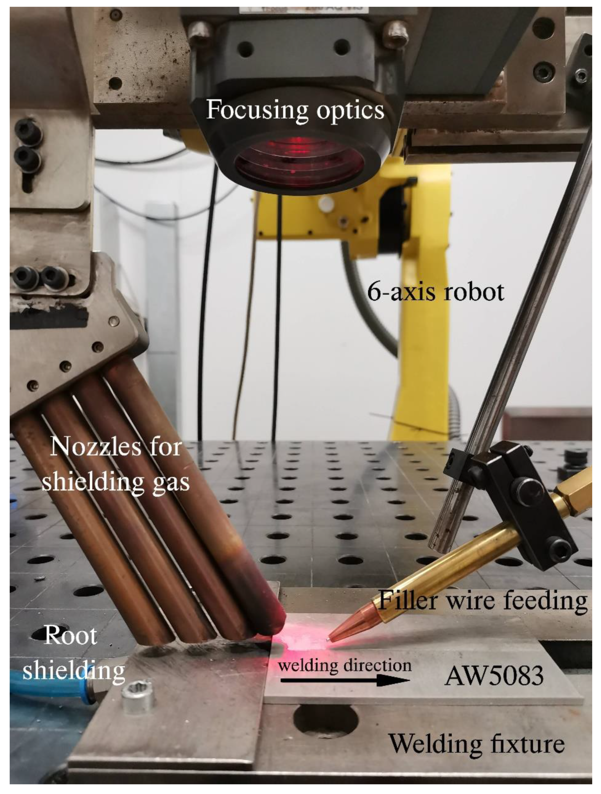
2.2. Laser Equipment and Welding Parameters

A TruDisk 4002 disk laser (Trumpf, Farmington, CT, USA) was selected for the welding in this experiment. The maximum power of the device is 2000 W. The quality of the laser beam was 8 mm.mrad, and the wavelength of the laser radiation was 1.03 μm. A BEO D70 focusing optic (Trumpf, Farmington, CT, USA) was used to transport the laser beam via a laser light cable with a radius of 200 μm. The focal length was 200 mm. Aluline He30 (Ar + 30 vol.% He) was used as a shielding gas under a variable flow rate. During the laser beam welding, the weld beads and weld root were protected from the ambient atmosphere. For each weld joint, 2/3 of the shielding gas volume was applied to the weld surface and the rest to the weld root. The gas flow rate at the output of the nozzle was measured by the flowmeter. The shielding gas flow rates were 12, 18, 24 or 30 L/min for the first four welds. The weld no. 5 was produced without shielding gas. The remaining welding parameters were kept constant, i.e., a 1.9 kW laser power, welding speed of 20 mm/s, and 0 mm focal position. A continuous-wave mode was used for the welds production. The diameter of the nozzle used for delivering shielding was 10 mm. During laser welding, the shielding gas flowed on the surface of the material through two nozzles out of four. The position of the nozzle was placed 5 mm above the surface of the base material. Shielding gas was delivered through tube connected to the side face of the fixture. The scheme of the experimental procedure is shown in Figure 1. The welding parameter values are given in Table 4.

2.3. Preparation of Welds

After the metallographic preparation of weld cross-sections, Barker reagent (5 mL HBF4 + 200 mL H2O) was used for the electrolytical etching of samples. The etching time was 90 s, at the voltage of 23.7 V. The light microscope NEOPHOT 32 (Carl Zeiss Microscopy GmbH, Jena, Germany) was employed to analyze the micro- and macrostructures. For more detailed study of the heat-affected zone, scanning electron microscope (SEM) JOEL 7600F (JEOL Ltd., Tokyo, Japan) was used. Sub-microstructure in both the base material and weld joint was analysed by a transmission electron microscope (JEOL USA, Inc. Peabody, MA, USA). For the TEM investigations, thin foils were mechanically cut from the characteristic area of the weld joints and ground to a thickness of about 80 μm. A TENUPOL 5 twin-jet electropolisher (Struers Inc., Cleveland, OH, USA) was used for polishing thin disks with a radius of 1.5 mm in 70% methanol and 30% nitric acid electrolyte at −30 °C and 19 V. The TEM analysis was carried out with a JEOL 200CX operating at 200 kV. The TEM analysis was coupled with electron diffraction, in order to identify the nature of minor phases. The fracture surfaces, after tensile testing, were observed by SEM. A Beuhler IndentaMet 1100 microhardness tester (Buehler, Lake Bluff, IL, USA) was used to determine the Vickers microhardness. The conditions of the measurement were as follows: time: 10 s; and load: 0.1 kg. In the HAZ, the indents were spaced at a distance of 200 μm. A LabTest E.3 machine (LABORTECH s.r.o., Opava, Czech Republic) for recording the tensile strength was used.

3. Results and Discussion

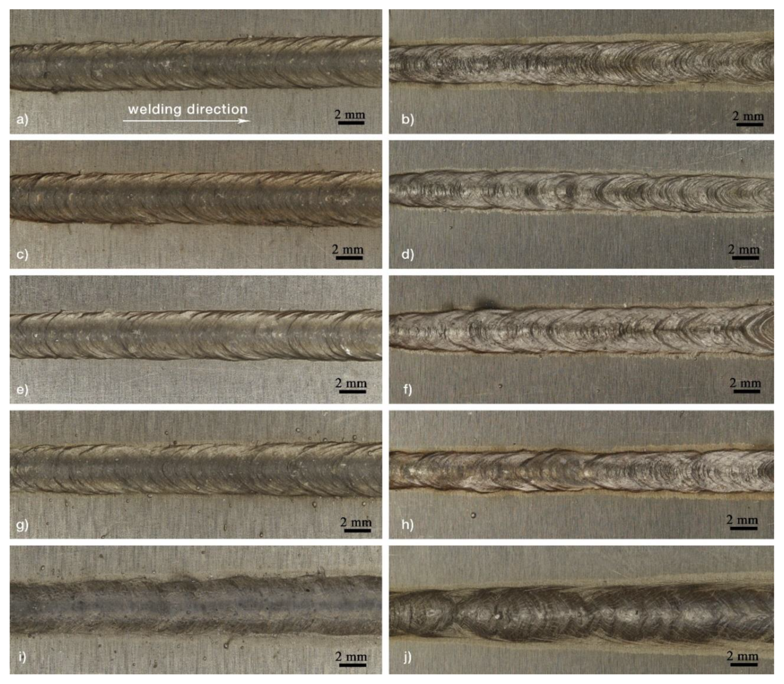
3.1. Appearance of Laser Welds

The weld beads and weld roots of the AW5083 welds created under a 30–0 L/min shielding gas flow rate are shown in Figure 2a–j. The change in weld beads width was caused by decrease in shielding gas flow. From the aforementioned results it follows that the decrease of shielding gas flow rate had an effect on the width of the weld beads. It is probable that it was caused by the distribution of heat input to the material. Figure 2a,b show the weld joint bead and weld joint root created using a laser beam with a power of 1900 W, and the wire feed rate was 1.1 m/min, the welding speed was 20 mm/s, and the focal position was 0 mm. Aluline He30 was used as a shielding gas, with a 30 L/min flow rate. The weld bead and root are smooth and regular. No spatter was present in the weld bead and weld root, and their widths were regular. Additional weld joints were produced with different gas flow rates. The laser weld joint shown in Figure 2c,d were created with the gas flow rate of 24 L/min. The width of the weld bead and its root are similar to that of the Figure 2a,b weld joint. Again, no spatter was observed, and the weld joint width and root widths were regular. The weld joint created under a gas flow rate of 18 L/min is depicted in Figure 2e,f. The weld joint width is the same as the weld joints observed previously, and its bead and root are smooth and regular. Welding without a shielding gas flow rate resulted in the creation of a narrower weld joint. Figure 2g,h show the weld bead and weld root produced under a shielding gas flow rate of 12 L/min. Spattering is present on the surface of the weld bead. This was caused by the lower shielding gas flow rate. The oxidized metal surface was caused because only 2/3 of the shielding gas flowed through the nozzle onto the surface of the weld joint. The width of the weld bead is regular, while the weld root is irregular. The weld that was created without a protective gas is shown in Figure 2i,j. It is evident that the weld joint is oxidized (gray colour). In this case, weld sagging, porosity, and spatter were observed. Wu et al. [51] found that the surface tension of the molten metal and the recoil pressure caused by evaporation were responsible for the spatter formation. The oxide layer formation on the surface of the molten metal is associated with the high affinity of Al to O2, which can prevent the escape of bubbles from the weld metal [52,53].
Cross-sections of the butt laser weld joints created by using different shielding gas flow rates are depicted in Figure 3. The geometry of the welds mainly depends on the welding parameters and also on the flow rate of shielding gas. In addition to the welding parameters, the use of different shielding gases and gas flow rates affects the geometry of the weld [54]. Tadamalle et al. [55] studied the influence of the laser welding parameters on the weld pool geometry. They found that the weld bead dimensions are more sensitive to the peak power input up to 1.7 kW and less sensitive beyond 1.7 kW. El-Batahgy et al. [56] found that the most pronounced effect on the weld profile is from the laser beam power, welding speed and focal distance. According to Matsuoka et al. [57] the weld bead geometry is determined by laser power, scanning velocity and beam spot diameter. The weld joint created under a 30 L/min shielding gas flow rate (Figure 3a) is concave (0.23 mm), and its root is excessively penetrated (0.37 mm). The width of the weld is 4.69 mm, and the width of the weld root is 4.17 mm. In this case, from the measured values it follows that the gas flow of a 20 L/min was applied to the surface of the material and the weld root was protected with a gas flow rate of a 10 L/min. The application of a 24 L/min shielding gas flow rate (Figure 3b) resulted in a decrease in the width of the weld. The recorded width of the weld was 4.54 mm, and the width of the weld root was 3.73 mm. The weld is smooth, and excessive penetration of 0.2 mm was observed. It was found that the weld joint was slightly concave (0.27 mm). The weld bead of the weld joint created under a 18 L/min shielding gas flow rate is similar to that of the previous weld joint (Figure 3c). Excessive penetration was also observed (0.24 mm), and the surface of the weld bead was concave (0.25 mm). The width of the weld dropped by a small amount in comparison to the previous case, from 4.54 to 4.47 mm, and the width of the weld root dropped to 3.37 mm. The application of a 12 L/min shielding gas flow rate (Figure 3d) resulted in a decrease in the width of the weld. The weld width was 4.31 mm, and its root width was 3.42 mm. Additionally, a concave weld bead (0.25 mm) and excessive penetration (0.2 mm) were observed. Sagging was detected in the weld joint created without the use of a shielding atmosphere (Figure 3e). Kuo et al. observed that a weld with a concave shape is a result of a larger gas pressure in the downward direction [14]. In this case, no protective gas was utilized. The concave shape of the weld joint (1.68 mm) and excessive penetration of 0.87 mm were a result of pressure caused by gravity on the molten pool. The width of the weld joint was 4.15 mm, and the width of its root was 4.68 mm. In this case, porosity was recorded in the WM. The radius of the biggest pore was 0.42 mm. The porosity and cracking of weld joints are the main problems in aluminum welding due to the high thermal expansion coefficient of Al, the large change in the volume upon solidification, and the wide solidification temperature range [58,59,60,61]. In the weld joints created under variable shielding gas flow rates, hot cracking was not detected. The laser weld joints became porous as a consequence of the Mg content and its evaporation, which caused the formation of gas bubbles and instability of the keyhole. Surface preparation decreases the hydrogen source, which causes porosity [62]. Xu et al. observed that with the increase in shielding gas flow rate, the electron temperature of plasma plume increases in the maintenance phase. With the increase of the shielding gas flow rate, the decrease in electron temperature was observed [63]. The aforementioned results could be associated with our results as it is obvious from Figure 3, the weld width slightly decreases with the lowering gas flow. When applying the higher gas flow rate, the temperature of electron is going to be lower indicating that a lower number of electrons could be transferred to plasma state. As it is known, plasma formation leads to the absorption of laser energy. From above-mentioned facts, it could be supposed that when higher gas flow rates resulted in smaller energy absorption by plasma plume resulting in higher utilization of laser energy to melt the base materials. Thus, the weld metal width for higher gas flow rate was reached.
Figure 4 depicts the relationship between the shielding gas flow rate and the weld width. The largest weld was created when a 30 L/min (a) shielding gas flow rate was used. Alternatively, the narrowest weld joint was created when no shielding gas was used (e). The lower the gas flow rate, the narrower the width of the WM. Ahn et al. found that the width of the weld joint created in argon was wider than that of the weld joint produced in a helium shielding atmosphere [64]. Reisgen et al. found that weld joints were shallow when Ar was used as the shielding atmosphere. They explained that this was due to a plume formation above the weld metal and thus instability of the welding process, which caused spatter and a poor surface appearance of the weld joint [65].
Similarly, authors in [66] observed the narrowest weld joint when laser welding of AISI304 stainless steel without shielding gas was carried out. They observed in this case the evident changing in laser keyhole shape. The plume behaviour was very unstable leading to periodic keyhole collapse. Contrary to our findings, they did not observe pores in the laser weld.

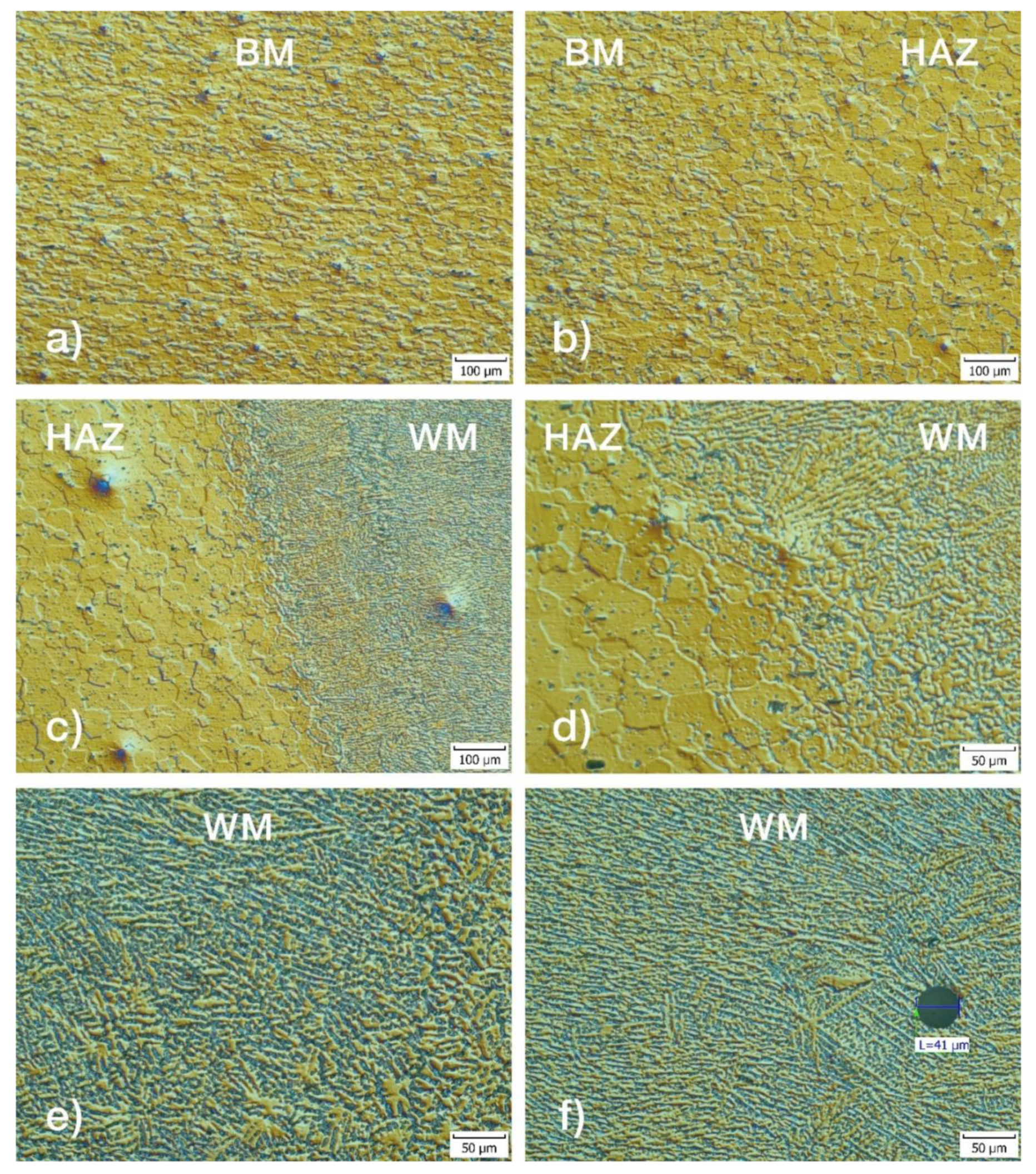
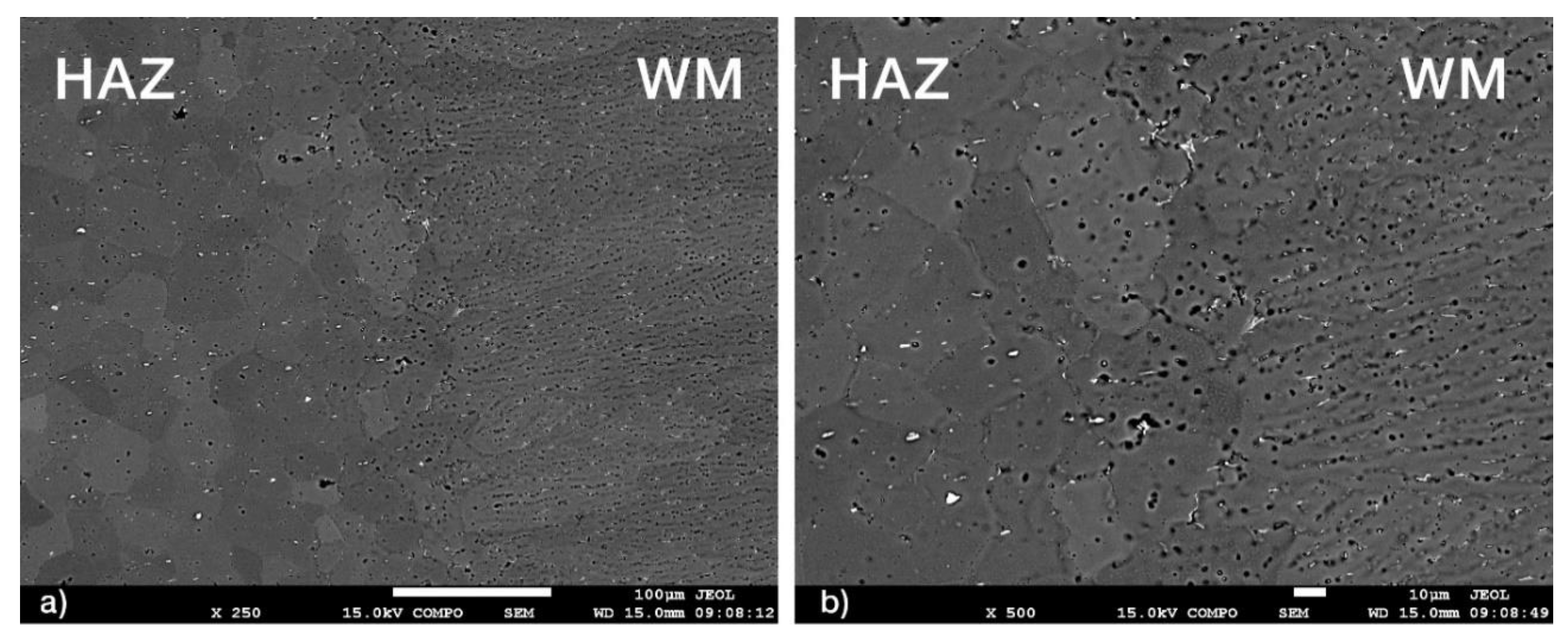
3.2. Light and Electron Microscopy

Figure 5 shows the microstructure of different zones of the 5083 aluminum alloy weld that was created at a gas flow rate of 30 L/min. The base metal is shown in Figure 5a. It is evident that the base metal is characterized by a fine grain microstructure, with an average grain size of 20 µm. Figure 5b shows the base metal–heat affected zone interface microstructure. The average grain size is 48 µm. The difference in the size of the grain in the HAZ is due to the low welding speed (20 mm/s), which caused a higher heat input and slow cooling rate. This results in excessive grain growth. The HAZ–WM interface is shown in Figure 5c. It is shown in a higher magnification in Figure 5d. It is obvious that the microstructure manifests clearly evident dendritic morphology. At the fusion boundary, columnar grains were observed. Moreover, it was found that the grains grew in the direction normal to the fusion boundary. During the epitaxial growth process, the starting columnar width of a grain of the FZ is appointed by the size of the base metal grains contiguous to the weld interface. It can be seen that a grain refinement occurred in the WM. This may be caused by the presence of Zr in the 5087 filler wire. Zhou et al. [67] observed a very similar phenomenon. They detected a grain refinement in laser welded 5083 aluminum alloy with an addition of 0.7 wt.% Zr. The presence of zirconium resulted in the formation of fine grains in the molten pool. AW5083 with zirconium exhibited excellent mechanical properties after printing and after heat treatment. Figure 5e,f shows the microstructure of different zones of the weld metal. In both figures, the dendritic microstructure and solute enrichment in the intermetallic areas can be observed. In the figures, a columnar dendritic formation with a solute microsegregation can be observed. The segregated solute is present in lower quantities, and it is thick and unbroken. Figure 5f shows the pore, which has a diameter of 41 µm. The pore was captured in the weld metal, which caused an evaporation of lightweight alloying elements.
Figure 6a,b show SEM images of the HAZ–WM interface of the weld joint created with a 30 L/min gas flow rate. The microstructure of the WM is composed mainly of the α-aluminum solid solution matrix. The inter-dendritic areas are supplemented in alloying elements. The brighter regions in the weld metal prove the presence of elements with a higher atomic number.

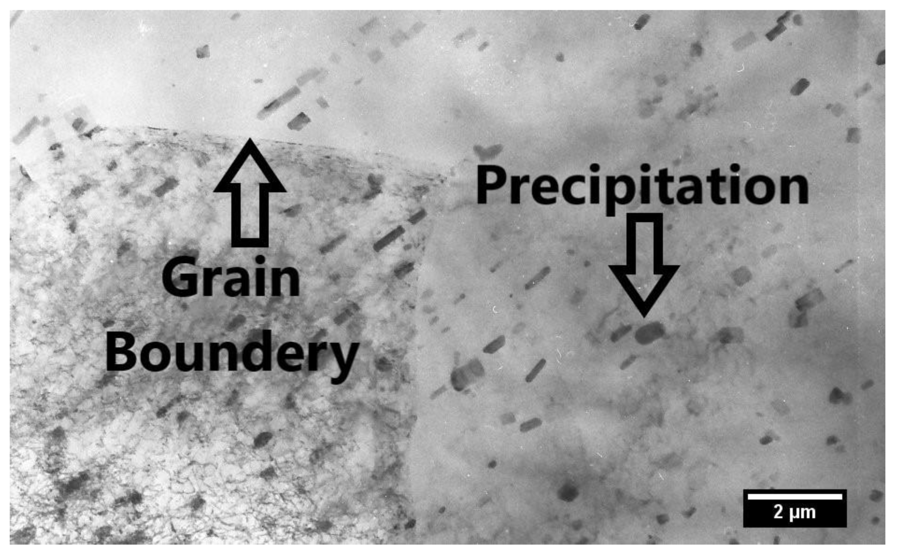
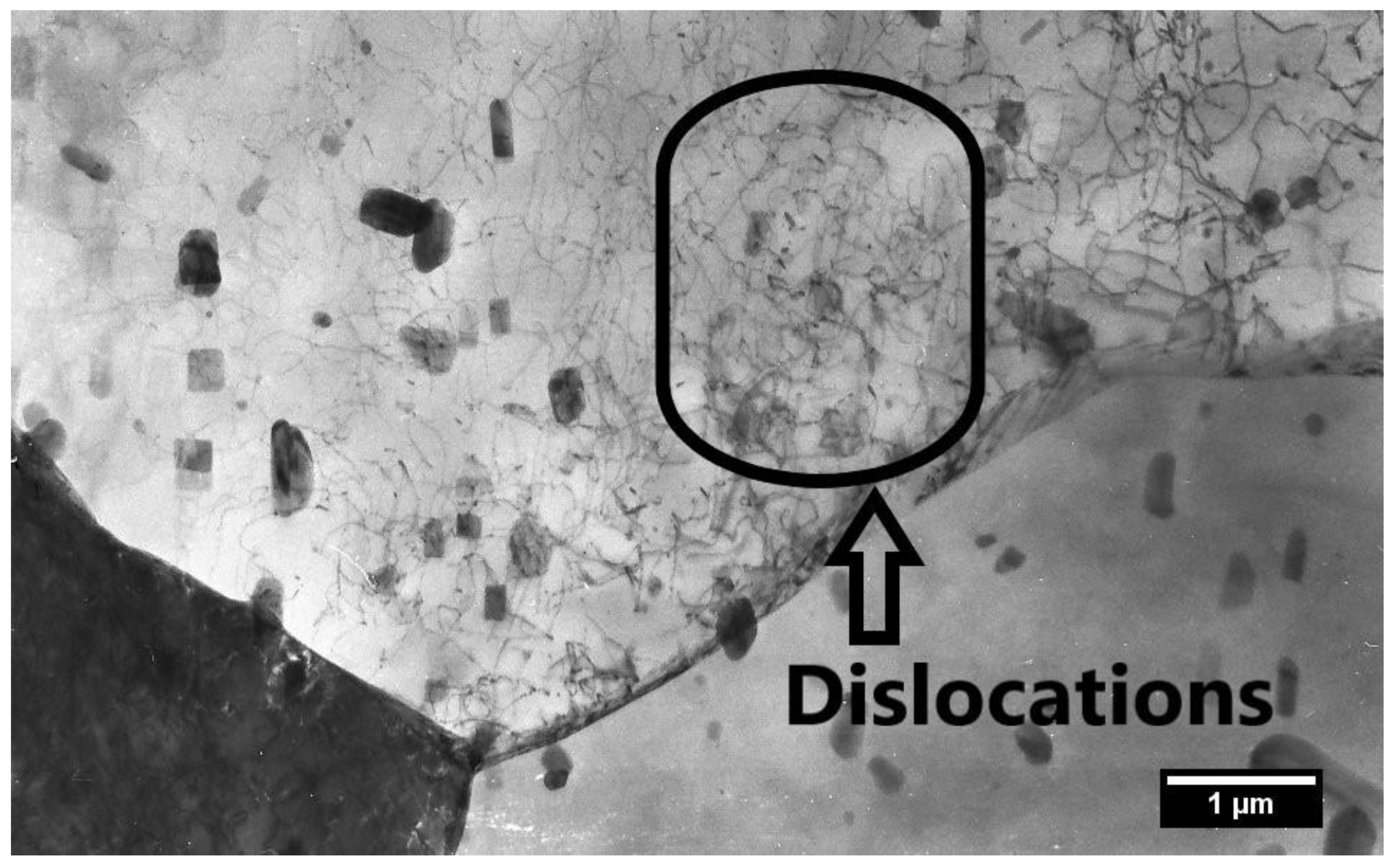
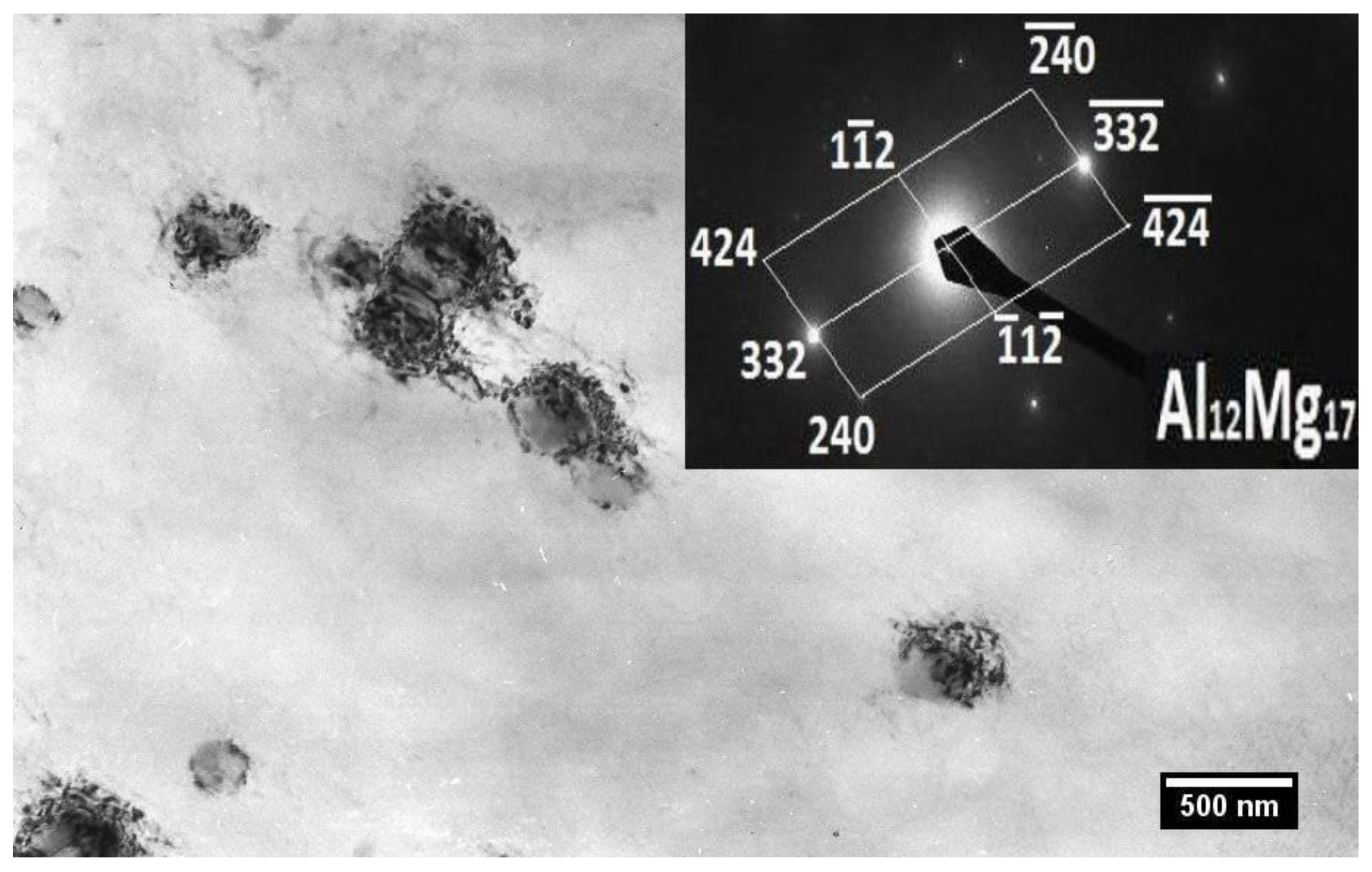
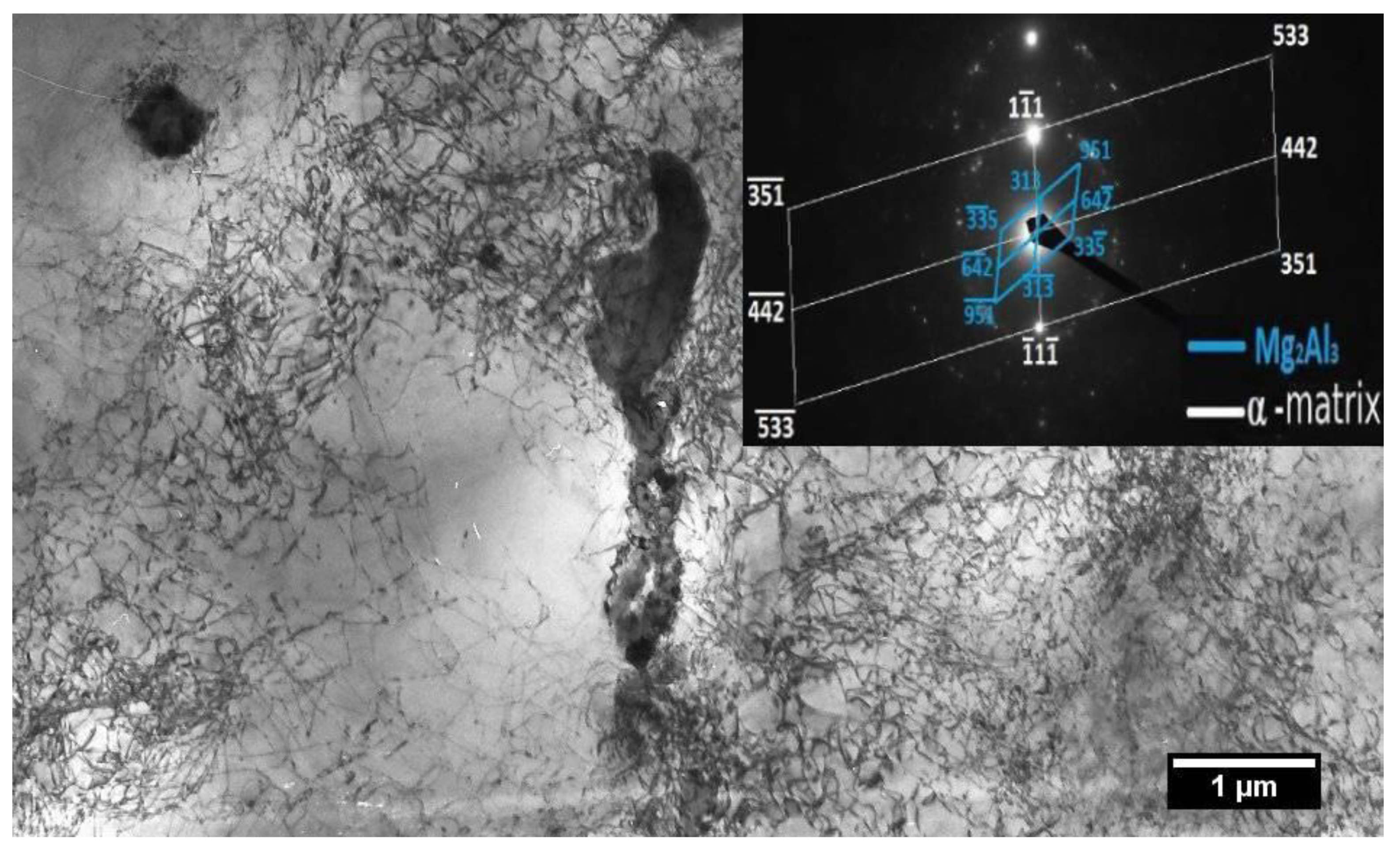
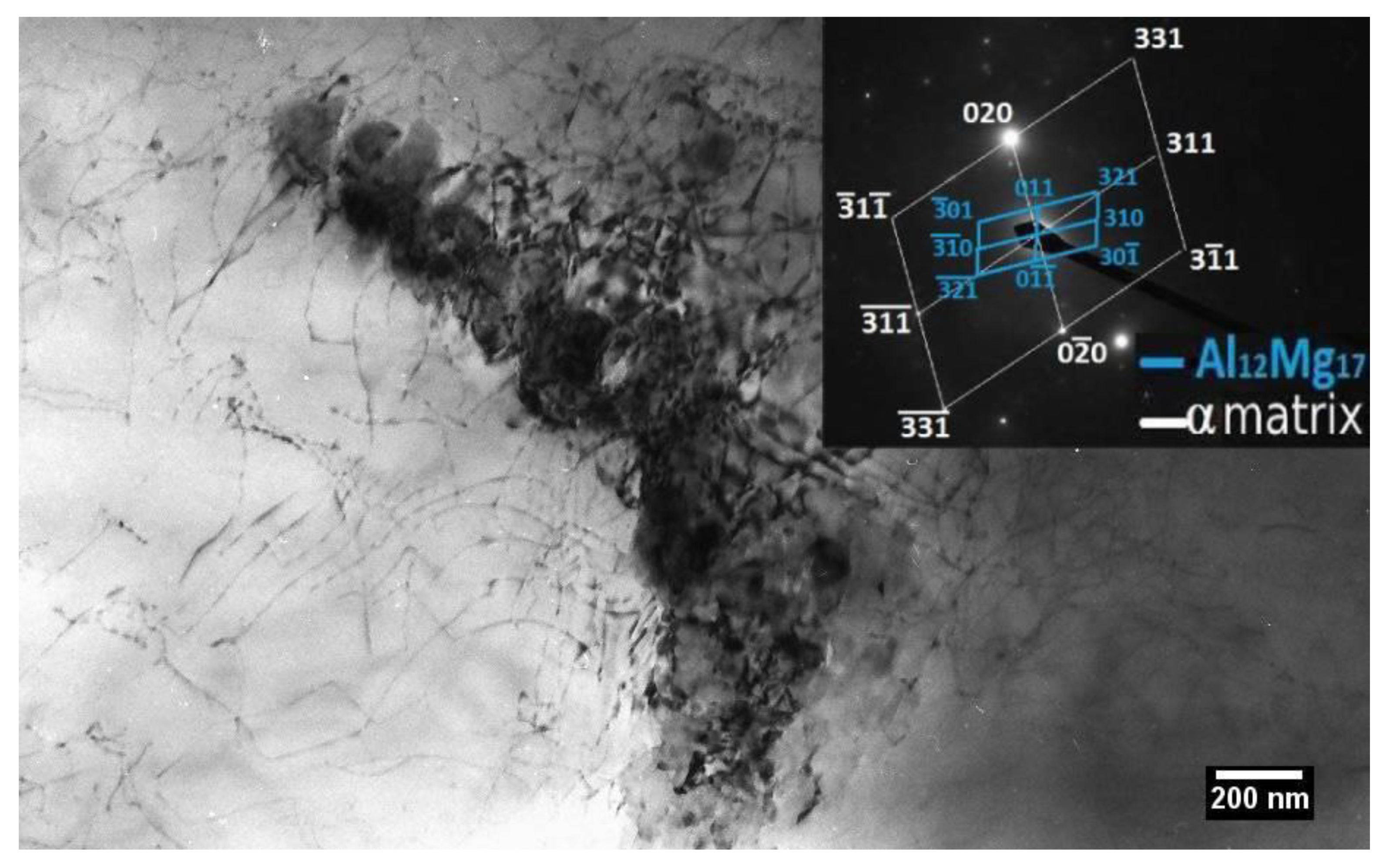
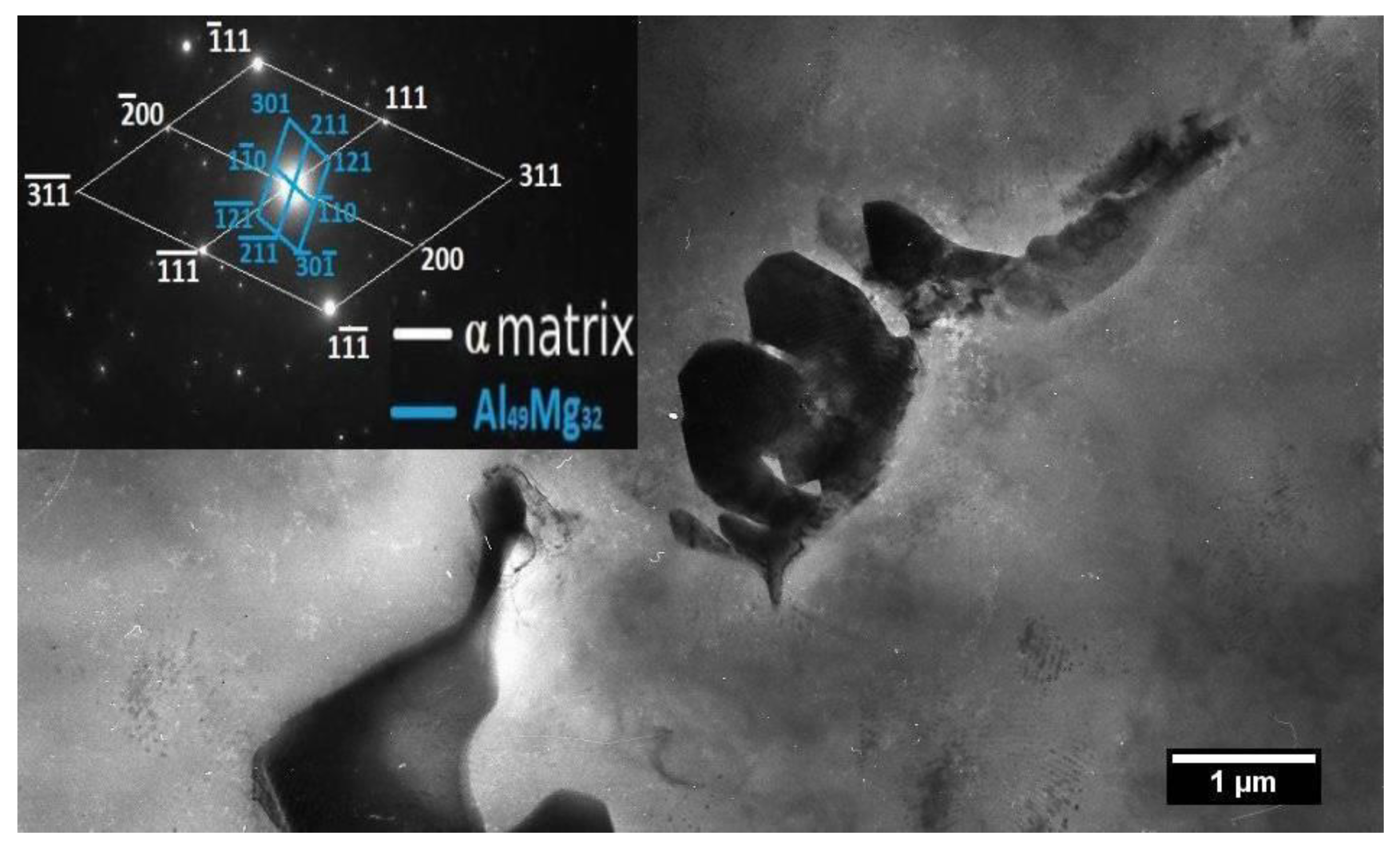
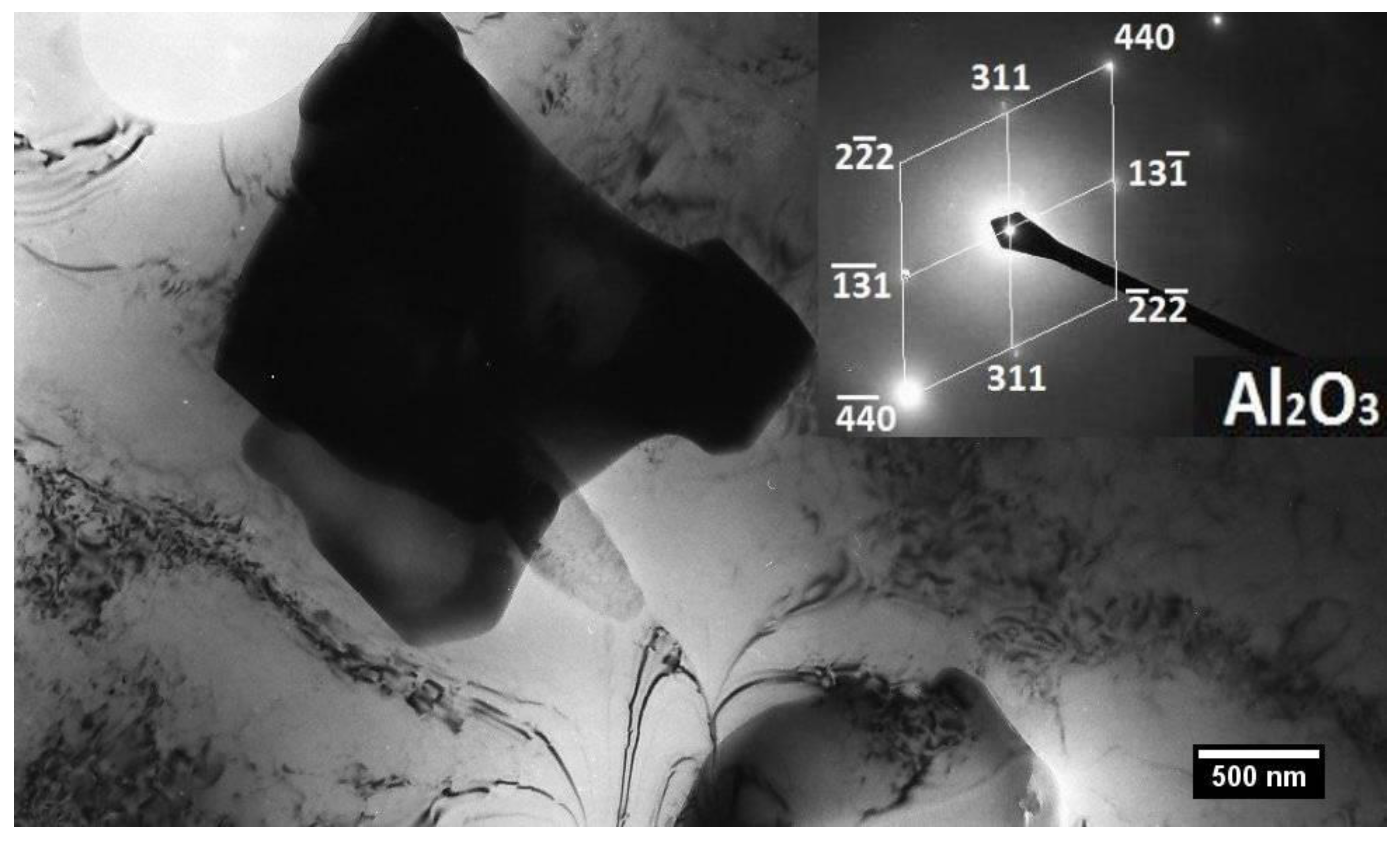
3.3. Transmission Electron Microscope (TEM) Analysis

The microstructure of the base metal (BM) observed by TEM is documented in Figure 7. The matrix microstructure of BM manifests polyhedral morphology and is formed by the substitution of the solid solution of the alloying elements in aluminum. An excessive precipitation of smaller particles with a regular geometric shape was observed inside grains. Alternatively, only a small amount of grain boundary precipitation was observed (Figure 8). These particles were identified as the Al12Mg17 intermetallic phase (Figure 9). A slight heterogeneity in the precipitate density, as well as the dislocation density, was also observed.
From a statistical point of view, the differences in the measured values of the tensile strength of weld joints, which were protected by different compositions of shielding gases are insignificant, see Section 3.5. The average tensile strength values of shielded weld joints ranged from 304 to 309 MPa. Alternatively, the material welded by using the shielding gas flow rate of 30 L/min manifests the highest ductility. Due to the highest average tensile strength and the highest average ductility, the microstructure of weld metal no. 1 (30 L/min) was studied by TEM analysis for achieving more details.
The microstructure of the weld metal has a dendritic morphology. The matrix consists of the solid solution of the alloying elements in aluminum. A significantly higher dislocation density was observed in the WM, compared to the BM. The majority of the particles are irregularly shaped. No particles were observed within the dendrites. The presence of the intermetallic phases, Mg2Al3, Al12Mg17, and Al49Mg32 (Figure 10, Figure 11 and Figure 12), were confirmed by electron diffraction. Secondary precipitation phases were mainly observed in the inter-dendritic area, Figure 11. Similar results are reported by Mofid et al. They recorded two inter-metallic compounds in the weld metal, namely, β-Al3Mg2 and γ-Al12Mg17 [68]. Goswami et al. detected the β-phase through high-resolution TEM analysis [30]. Ding et al. [69] found β-phase precipitates along grain boundaries. Choi et al. [70] studied the behaviour of β-phase (Al3Mg2) in AA 5083 during friction stir welding. The results of electron probe micro-analyzer analysis showed that the precipitated β-phase (Al3Mg2) existed along the grain boundaries in the matrix. Zhang et al. [37] found that most particles in the AA5083 aluminum alloy are β-phase. They also recorded the presence of a small number of Al x Mn dispersoids. Observed dispersoids had a square or rectangular shape, while the β-phase had a random or irregular shape. Panteli et al. [71] detected in their study the presence of both phases a β-Al3Mg2 and γ-Al12Mg17 by XRD. Shahid et al. [72] recorded the same results in their study. In Figure 13, Al2O3 is present, which is probably the cause of a brittle fracture in the WM of the unshielded weld joint. A higher amount of Al2O3 particles was recorded in the unshielded weld joint in comparison to the protected weld metal.
Tamasgavabari et al. [73] observed, that area fraction of intermetallic compound (IMC) was lower in the weld metal of AA5083-H321 aluminum alloy than in BM. With the application of vibration force during GMAW, the size and quantity of IMC increased.

3.4. Microhardness Measurements

Figure 14 shows the microhardness profiles throughout the welds made by using of different shielding gas flow rates. The microhardness course was measured in the middle of the weld joint. The distance between indents was 200 μm. In all cases, an increase in the microhardness was observed from the BM toward the WM. This may be caused by the use of 5087 filler wire containing zirconium that induces grain refinement in the WM, thus microhardness increase. The highest microhardness value was measured in the weld metal. It is evident that the gas flow rate had an influence on the microhardness of the specimens. The maximum average microhardness value was observed in weld no.5. This weld joint was not protected against the ambient atmosphere. The highest porosity and the lowest strength was observed in this weld joint in comparison to the protected welds. Increased values of the microhardness can be caused by the oxidation of the molten weld pool because of the lack of protection of the WM during laser welding. The average weld metal microhardness was 63.9 HV0.1. If a 30 L/min (weld no.1) shielding gas flow rate of the Aluline He30 was used then the average microhardness was lower, namely, 55.4 HV0.1. An increase in the weld metal microhardness values in comparison to the base metal was caused by a grain refinement in the fusion zone. When the 24 L/min gas flow rate was used, the average microhardness increased to 57.2 HV0.1. A microhardness of 58.4 HV0.1 was measured under the 18 L/min shielding gas flow rate. The microhardness increased to 60.2 HV0.1 in the last shielded weld joint, which was protected by a 12 L/min shielding gas flow rate. With the lowest shielding gas flow rate, the highest oxidation of the molten metal and thus the highest microhardness values were observed. Prokić-Cvetković [58] achieved similar results when He was utilized as a protective gas. The hardness values of the WM were slightly higher, leading to the conclusion that a higher quantity of helium increased the hardness. In the work of Ahn et al. [64], different microhardness values were observed. They analyzed AA2024 aluminum alloy weld joints, which were created in argon and helium shielding gases. Weld joints created in helium had a lower or comparable hardness to welds created in argon. The researchers explained this result by pointing to the raised heat input, which can be attributed to the higher thermal conduction of helium.

3.5. Tensile Test

Figure 15 shows the dimensions of the tensile test specimen. Figure 16 shows the variations in the tensile strength on the gas flow rate. The average value of the three tested samples for every weld was computed. The maximum tensile strength was observed when the 30 L/min shielding gas flow rate was used, namely, Rm = 309 MPa (±2.94). These specimens also manifested the highest ductility, i.e., 29.96% (±0.49). The weld joint created under the 24 L/min shielding gas flow rate achieved a tensile strength of 307 MPa (±2.52), and its ductility was 27.25% (± 0.45). The tensile strength of the weld joint produced under the 18 L/min shielding gas flow rate was Rm = 305 MPa (±2.45) and ductility value was 26.03% (±0.56). The weld joint produced under the 12 L/min shielding gas flow rate achieved a tensile strength of 304 MPa (±3.27) and ductility value was 25.64% (±1.05). A tensile strength of only 160 MPa was recorded when the weld joint was welded in the ambient atmosphere without the use of a protective gas. This result can be attributed to the high porosity of the WM. A possible reason for the pore formation in the WM is a keyhole collapse during the course of welding. Elements with relatively low boiling points, such as magnesium, tend to evaporate during laser welding. Developed gases are captured by the molten metal in the weld pool, which in turn leads to the formation of pores [74]. In [75], Al2O3 was found to be hygroscopic and supported the capture of moisture from the atmosphere. Toda et al. [76] found that the mechanical properties of aluminum alloys are susceptible to the development of micropores. Aside from this fact, they indicated that the lower ductility and decreased mechanical properties and fatigue characteristics can be related to the high density of the micropores in aluminum alloys. They also indicated that the tensile strength decreased substantially when the volume of micropores increased.
The stress–strain curves for the welds created at various gas flow rates are shown in Figure 17. The gas-shielded laser weld joints are characterized by much greater area below the stress–strain curves than can be seen for a non-protected weld joint. This indicates much better ductility (and toughness being represented by work until the fracture) of joints produced with use of shielding gas. On the other hand, low ductility (and toughness) of non-protected joint may be associated with the formation of heterogeneities and micro-pores, as above discussed.

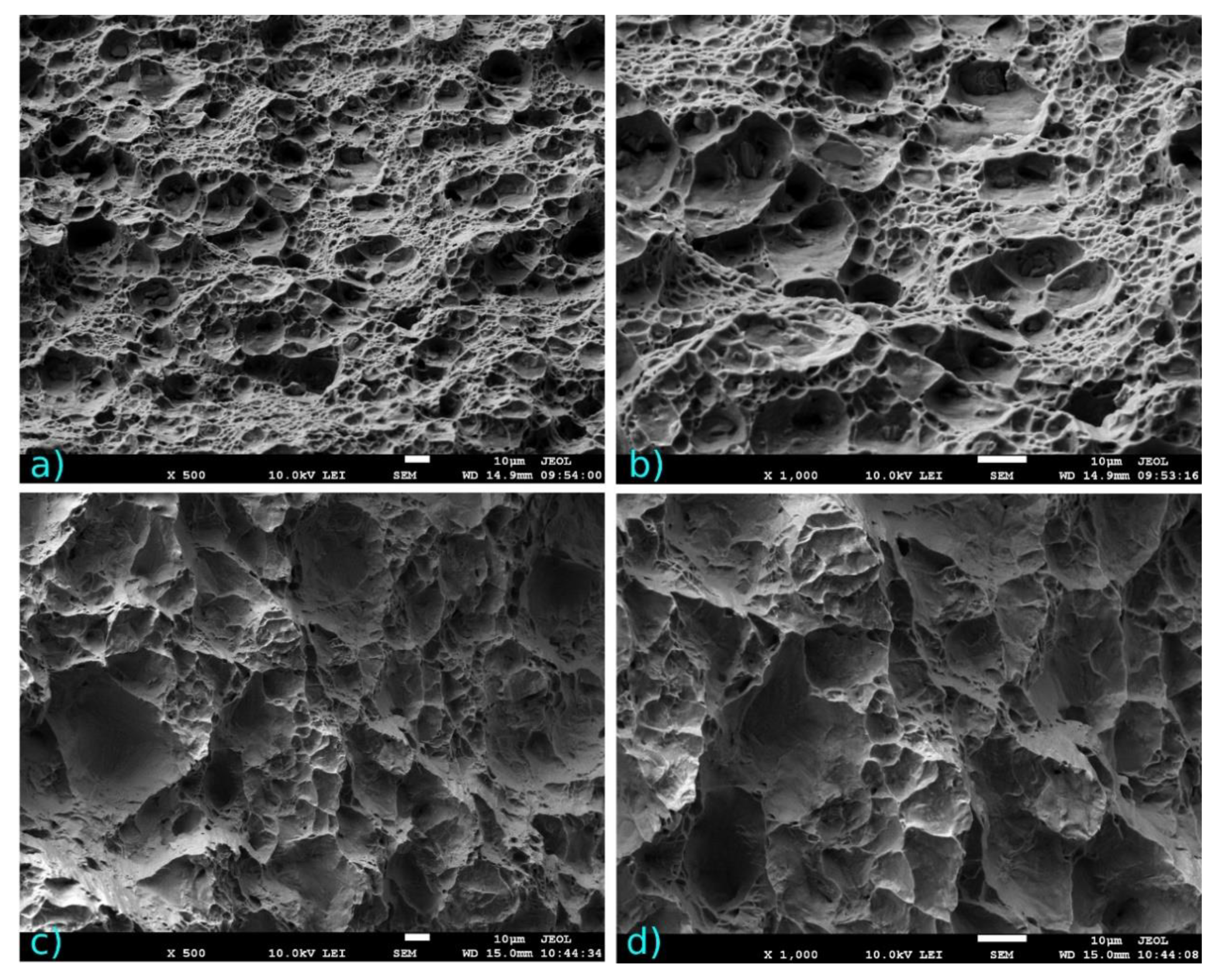
3.6. Fracture Surfaces Analysis

SEM images of the fracture surface of the welds created with the 30 L/min gas flow rate are shown in Figure 18a,b. From the images of the fracture surface, a ductile fracture can be observed. This fact is attributed to the dimples that are present on the fracture surface. The application of Aluline He30 (30 L/min) was effective, because no pore was observed on the fracture surfaces. Except for the weld that was produced without the use of shielding gas (Figure 18c,d), a fracture was observed in the base metal. From the images (Figure 18c,d) of the fracture surface, a brittle fracture can be observed. The sample fractured in the WM. Understanding the connection between the fracture behavior and microstructure is essential. Because many secondary phase particles are contained in the metal, they cause ductile fractures of aluminum alloy. The ductile fracture process is as follows: nucleation > growth > coalescence of the voids. In the void nucleus are particles of the precipitate, inclusion, or dispersoid [77].

4. Conclusions

In this work, the effect of process parameters on the microstructure and mechanical properties of AW5083 aluminum laser weld joints was investigated. For joining butt laser welds, 5087 (AlMg4.5MnZr) filler wire, with a diameter of 1.2 mm, was used. Aluline He30 was used as the shielding gas. Additionally, the influence of different shielding gas flow rates on the microstructure, mechanical properties, and weld shape was revealed. From the results obtained, the following observations can be made:
(1)
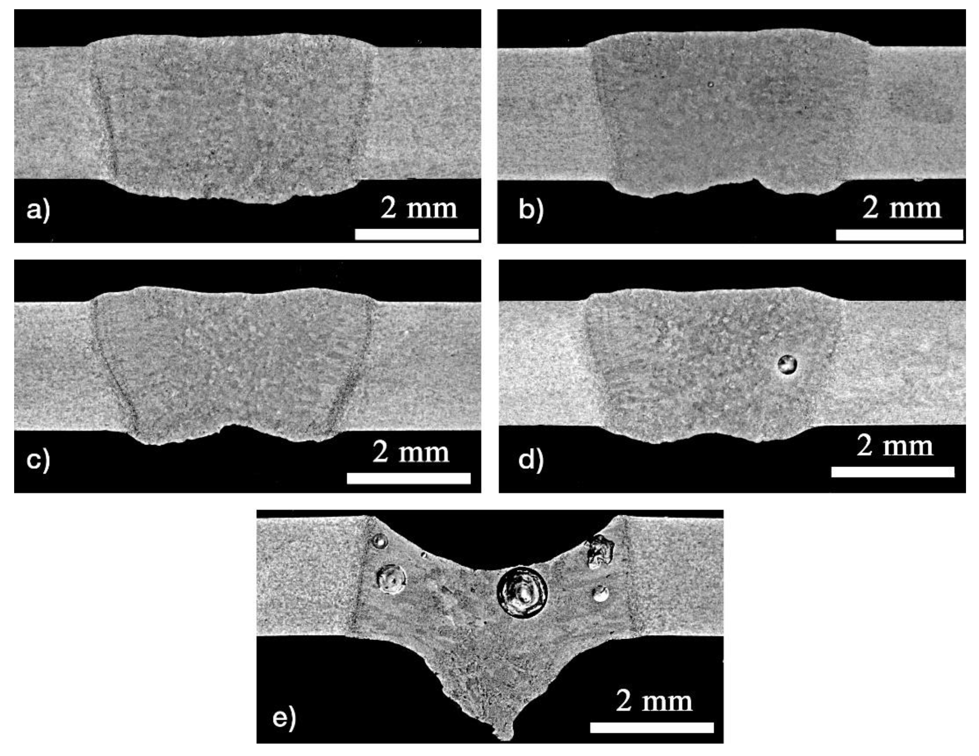
The weld joint created under the 30 L/min shielding gas flow rate was the widest. A concave shape of 0.23 mm and excessive penetration of 0.37 mm were recorded. A weld width of 4.69 mm and root width of 4.17 mm were measured. In the unshielded weld joint, a concave shape of 1.68 mm and excessive penetration of 0.87 mm were recorded. A weld width of 4.15 mm and root width of 4.68 mm were measured. In this case, the WM was found to be porous. The diameter of the biggest pore was 0.84 mm.
(2)
The weld metal microstructure is formed by a dendritic structure with an average grain size of 20 µm. This is caused by zirconium, which is an alloying element present in the filler wire and acts as a grain refiner. The high cooling rate of laser beam welding contributed to the grain refinement. Columnar grains were observed at the fusion boundary. The grains grew in a direction normal to the fusion boundary. Equiaxed grains were observed in the middle of the fusion zone.
(3)
Three intermetallic compounds, β-Al3Mg2, γ-Al12Mg17, and Al49Mg32, were observed by TEM analysis. A larger number of Al2O3 particles was recorded in the unshielded weld joint in comparison with the protected weld metal, which is probably due to the brittle fracture in the WM of the unshielded weld joint.
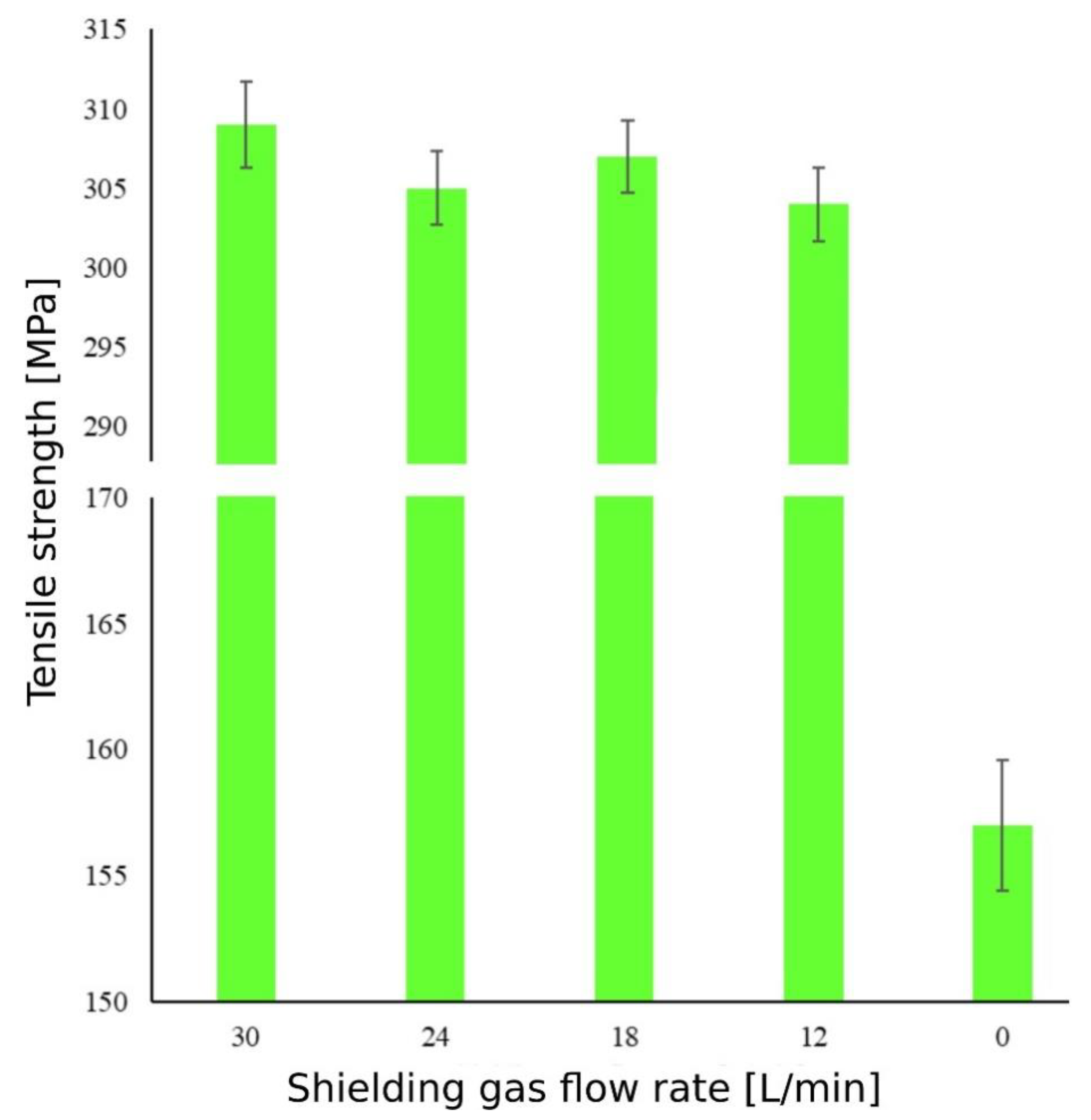
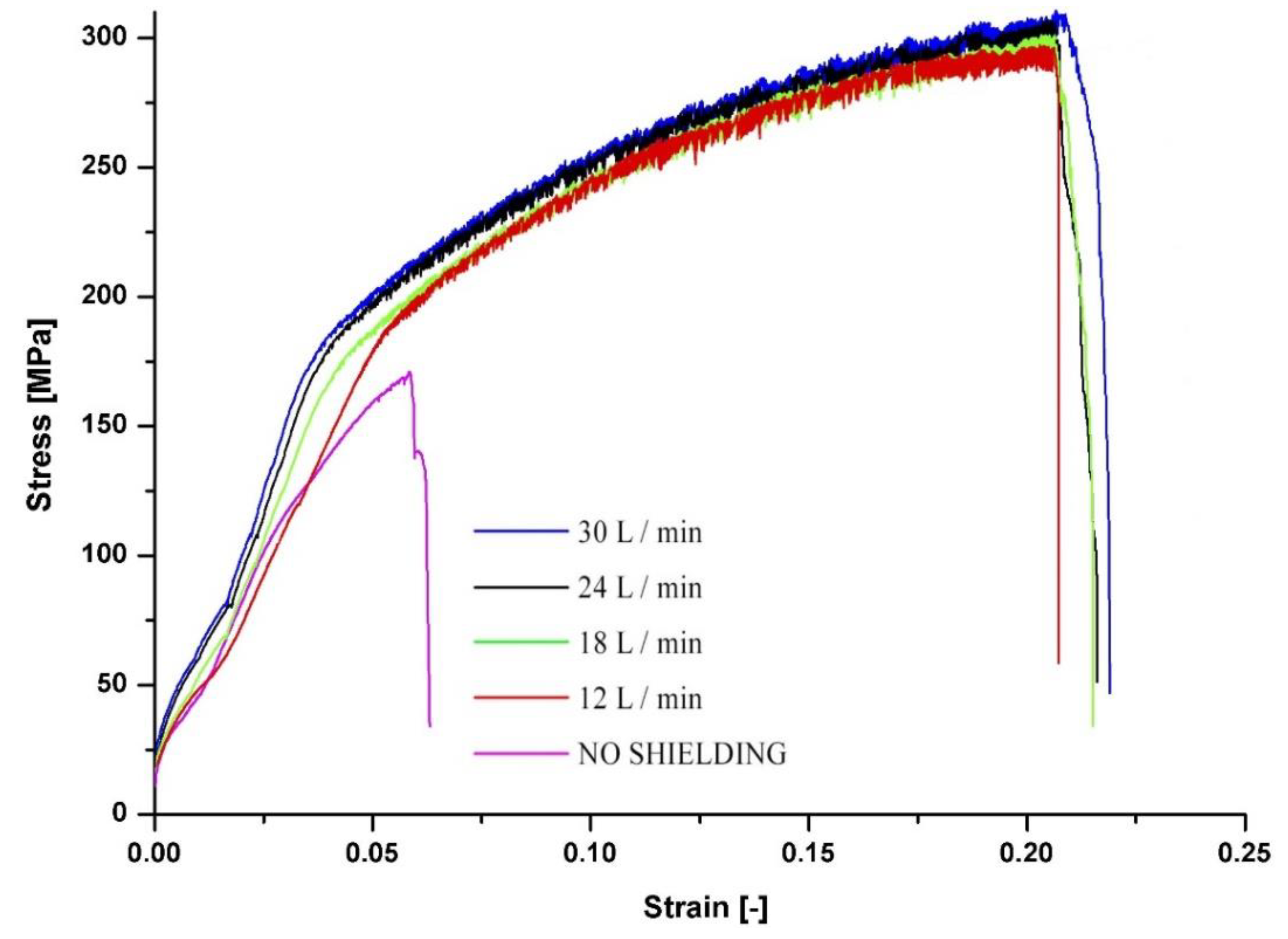
(4)
When 30 L/min of Aluline He30 was used, the highest tensile strength (Rm = 309 MPa), at the highest ductility, was recorded. The weld joint was fractured in the base material. The lowest tensile strength (Rm = 160 MPa) was recorded when no shielding gas was used. In this case, a fracture occurred in the weld metal because of a large number of pores.
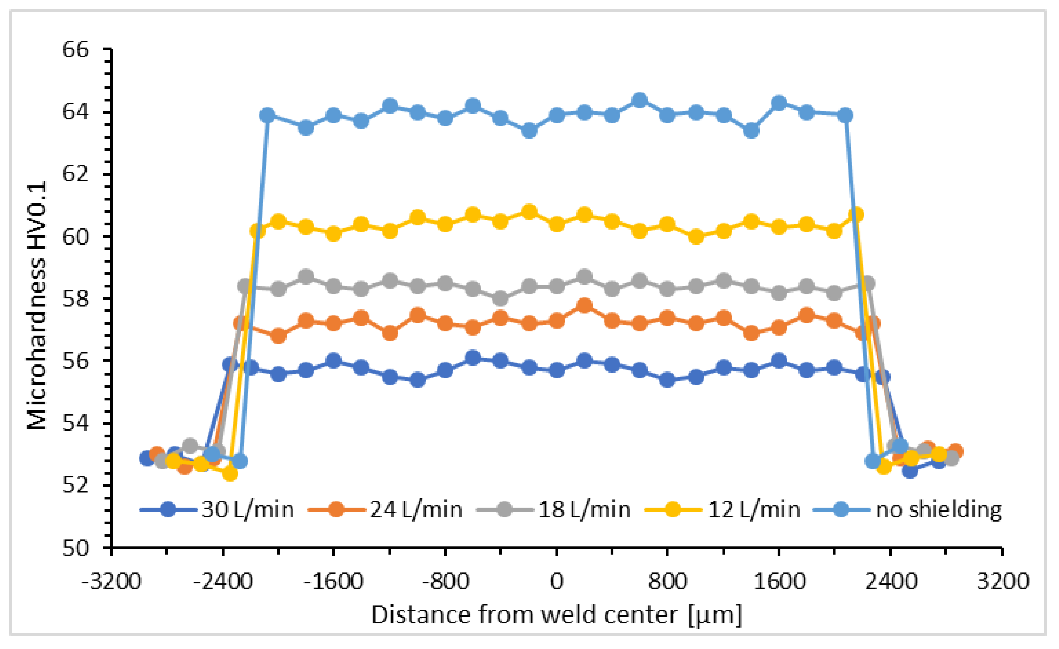
(5)
The lowest average microhardness was measured in the weld that was protected under the 30 L/min gas flow rate during welding, namely 55.4 HV0.1. An increase in the microhardness was caused by the grain refinement due to the presence of Zr in the filler wire and the high cooling rate that is characteristic of laser beam welding. Conversely, the highest microhardness (63.9 HV0.1) was recorded in weld no. 5. Increased values of the microhardness are probably caused by oxidation of the molten weld pool, because of the lack of protection of the WM during laser welding. It is evident, from the recorded values of the microhardness, that the gas flow rate had an effect.
(6)
The best results were obtained when the following welding parameters were used: a laser power of 1900 W, speed of welding of 20 mm/s, focal point of 0 mm, filler wire feed rate of 1.1 m/min, and gas flow rate of 30 L/min. This study could have implications for industry as laser weld joints without defects were produced. Further research on the use of shielding gas with a higher flow rate and the influence of the gas flow rate on porosity in the weld metal are merited. The use of computed tomography to investigate the microporosity in the weld metal should also be explored.

Author Contributions

Conceptualization, M.V. (Maroš Vyskoč); methodology, M.S. (Miroslav Sahul) and P.J.; formal analysis, M.V. (Maroš Vyskoč), M.D. and M.S. (Martin Sahul); investigation, M.V. (Maroš Vyskoč) and M.S. (Miroslav Sahul), M.D., P.J.; data curation, M.S. (Miroslav Sahul); writing—original draft preparation, M.V. (Maroš Vyskoč); writing—review and editing, P.J. and M.S. (Miroslav Sahul); visualization, M.V. (Monika Vyskočová); supervision, P.J.; project administration, M.M. and P.J.; funding acquisition, M.M. and P.J. All authors have read and agreed to the published version of the manuscript.

Funding

This publication was supported by the Operational Program for Research and Innovation of the Scientific and Research Centre of Excellence SlovakION for Material and Interdisciplinary Research. The code of the project, called ITMS2014+, is 313011W085. It was co-financed by the European Regional Development Fund. This publication was funded by the Slovak Research and Development Agency under the contract No. APVV-15-0319. The paper is also a result of implementation of the project DIACHARMAT (Excellent team of diagnostics and characterization of materials). The authors are grateful to financial support for project implementation.

Conflicts of Interest

The authors declare no conflict of interest.

References

  1. Sahul, M.; Sahul, M.; Haršáni, M.; Dománková, M. On the microstructure and mechanical properties of AW2099 aluminum lithium alloy joints produced with electron beam welding. Mater. Lett. 2020, 276, 128276. [Google Scholar] [CrossRef]
  2. Msomi, V.; Mbana, N.; Mabuwa, S. Microstructural analysis of the friction stir welded 1050-H14 and 5083-H111 aluminum alloys. Mater. Today Proc. 2020, 26, 189–192. [Google Scholar]
  3. Huang, L.; Wu, D.; Hua, X.; Liu, S.; Jiang, Z.; Li, F.; Wang, H.; Shi, S. Effect of the welding direction on the microstructural characterization in fiber laser-GMAW hybrid welding of 5083 aluminum alloy. J. Manuf. Process. 2018, 31, 514–522. [Google Scholar] [CrossRef]
  4. Wu, D.; Hua, X.; Huang, L.; Zhao, J. Numerical simulation of spatter formation during fiber laser welding of 5083 aluminum alloy at full penetration condition. Opt. Laser Technol. 2018, 100, 157–164. [Google Scholar] [CrossRef] [Green Version]
  5. Reis, L.; Infante, V.; Freitas, M.; Duarte, S.; Moreira, P.; Castro, P. Fatigue behaviour of aluminum lap joints produced by laser beam and friction stir welding. Procedia Eng. 2014, 74, 293–296. [Google Scholar]
  6. Ning, J.; Zhang, L.-J.; Yin, X.-Q.; Zhang, J.-X.; Na, S.-J. Mechanism study on the effects of power modulation on energy coupling efficiency in infrared laser welding of highly-reflective materials. Mater. Des. 2019, 178, 107871. [Google Scholar] [CrossRef]
  7. Caiazzo, F.; Alfieri, V.; Cardaropoli, F.; Corrado, G.; Sergi, V. Characterization of disk-laser dissimilar welding of titanium alloy Ti-6Al-4V to aluminum alloy 2024. SPIE LASE 2013, 8603. [Google Scholar] [CrossRef]
  8. Chen, S.; Li, L.; Chen, Y.; Dai, J.; Huang, J. Improving interfacial reaction nonhomogeneity during laser welding–brazing aluminum to titanium. Mater. Des. 2011, 32, 4408–4416. [Google Scholar] [CrossRef]
  9. Kashani, H.T.; Kah, P.; Martikainen, J. Laser Overlap Welding of Zinc-coated Steel on Aluminum Alloy. Phys. Procedia 2015, 78, 265–271. [Google Scholar] [CrossRef] [Green Version]
  10. Vyskoč, M.; Sahul, M.; Sahul, M. Effect of Shielding Gas on the Properties of AW 5083 Aluminum Alloy Laser Weld Joints. J. Mater. Eng. Perform. 2018, 27, 2993–3006. [Google Scholar] [CrossRef]
  11. Schultz, V.; Seefeld, T.; Vollertsen, F. Gap bridging ability in laser beam welding of thin aluminum sheets. Int. Congr. Appl. Lasers Electro-Optics 2014, 56, 545. [Google Scholar] [CrossRef]
  12. Wu, A.; Song, Z.; Nakata, K.; Liao, J.; Zhou, L. Interface and properties of the friction stir welded joints of titanium alloy Ti6Al4V with aluminum alloy 6061. Mater. Des. 2015, 71, 85–92. [Google Scholar] [CrossRef]
  13. Kalaiselvan, K.; Elango, A.; Nagarajan, N.; Mathiyazagan, N. Studies on Ti/Al Sheet Joint using Laser Beam Welding—A Review. Int. J. Chem. Nucl. Mater. Metall. Eng. 2014, 8, 795–798. [Google Scholar]
  14. Kuo, T.-Y.; Lin, Y.-T. Effects of Shielding Gas Flow Rate and Power Waveform on Nd:YAG Laser Welding of A5754-O Aluminum Alloy. Mater. Trans. 2006, 47, 1365–1373. [Google Scholar] [CrossRef] [Green Version]
  15. Katayama, S.; Kawahito, Y.; Mizutani, M. Elucidation of laser welding phenomena and factors affecting weld penetration and welding defects. Phys. Procedia 2010, 5, 9–17. [Google Scholar] [CrossRef] [Green Version]
  16. Mittelstädt, C.; Seefeld, T.; Woizeschke, P.; Vollertsen, F. Laser welding of hidden T-joints with lateral beam oscillation. Procedia CIRP 2018, 74, 456–460. [Google Scholar] [CrossRef]
  17. Kalaiselvan, K.; Elango, A. Mechanical Properties on Ti/Al Dissimilar Metal Butt Joint using Laser Beam Welding. J. Chem. Pharm. Sci. 2015, 6, 65–68. [Google Scholar]
  18. Blackburn, J.; Allen, C.; Hilton, P.; Li, L. Nd:YAG laser welding of titanium alloys using a directed gas jet. J. Laser Appl. 2010, 22, 71–78. [Google Scholar] [CrossRef]
  19. Kawahito, Y.; Matsumoto, N.; Abe, Y.; Katayama, S. Relationship of laser absorption to keyhole luminium in high power fiber laser welding of stainless steel and aluminum alloy. J. Mat. Proc. Tech. 2011, 211, 1563–1568. [Google Scholar] [CrossRef]
  20. Paradiso, V.; Rubino, F.; Carlone, P.; Palazzo, G. Magnesium and aluminum alloys dissimilar joining by friction stir welding. Preced. Eng. 2017, 183, 239–244. [Google Scholar] [CrossRef]
  21. Meco, S.; Pardal, G.; Ganguly, S.; Williams, S.; McPherson, N. Application of laser in seam welding og dissimilar steel to aluminum joints fot thick structural components. Opt. Lasers Eng. 2015, 67, 22–30. [Google Scholar] [CrossRef] [Green Version]
  22. Enz, J.; Riekehr, S.; Ventzke, V.; Sotirov, N.; Kashaev, N. Laser welding of high-strength aluminum alloys for the sheet metal forming process. Procedia CIRP 2014, 18, 203–208. [Google Scholar] [CrossRef] [Green Version]
  23. Sahul, M.; Sahul, M.; Vyskoč, M.; Čaplovič, L.; Pašák, M. Disk Laser Weld Brazing of AW5083 Aluminum Alloy with Titanium Grade 2. J. Mater. Eng. Perform. 2017, 26, 1346–1357. [Google Scholar] [CrossRef]
  24. Chen, S.H.; Li, L.Q.; Chen, Y.B.; Liu, D.J. Si diffusion behavior during laser welding-brazing of Al alloy and Ti alloy with Al-12Si filler wire. Trans. Nonferrous Met. Soc. China 2010, 20, 64–70. [Google Scholar] [CrossRef]
  25. Chen, Y.H.; Ni, Q.; Ke, L.M. Interface characteristic of friction stir welding lap joints of Ti/Al dissimilar alloys. Trans. Nonferrous Met. Soc. China 2012, 22, 299–304. [Google Scholar] [CrossRef]
  26. Ahn, J.; Chen, L.; He, E.; Dear, J.P.; Davies, C.M. Optimisation of process parameters and weld shape of high power Yb-fibre laser welded 2024-T3 aluminum alloy. J. Manuf. Process. 2018, 34, 70–85. [Google Scholar] [CrossRef]
  27. Beiranvand, Z.M.; Ghaini, F.M.; Moosavy, H.N.; Sheikhi, M.; Torkamany, M.J.; Moradi, M. The relation between magnesium evaporation and laser absorption and weld penetration in pulsed laser welding of aluminum alloys: Experimental and numerical investigations. Opt. Laser Technol. 2020, 128, 106170. [Google Scholar] [CrossRef]
  28. Xu, Y.; Ke, L.; Mao, Y.; Liu, Q.; Xie, J.; Zeng, H. Formation Investigation of Intermetallic Compounds of Thick Plate Al/Mg Alloys Joint by Friction Stir Welding. Materials 2019, 12, 2661. [Google Scholar] [CrossRef] [Green Version]
  29. Venkateswaran, P.; Reynolds, A. Factors affecting the properties of Friction Stir Welds between aluminum and magnesium alloys. Mater. Sci. Eng. A 2012, 545, 26–37. [Google Scholar] [CrossRef]
  30. Goswami, R.; Spanos, G.; Pao, P.S.; Holtz, R.L. Precipitation behavior of the β phase in Al-5083. Mater. Sci. Eng. 2010, 527, 1089–1095. [Google Scholar] [CrossRef]
  31. Huang, L.; Hua, X.; Wu, D.; Fang, L.; Cai, Y.; Ye, Y. Effect of magnesium content on keyhole-induced porosity formation and distribution in aluminum alloys laser welding. J. Manuf. Process. 2018, 33, 43–53. [Google Scholar] [CrossRef]
  32. Bunaziv, I.; Akselsen, O.M.; Salminen, A.; Unt, A. Fiber laser-MIG hybrid welding of 5 mm 5083 aluminum alloy. J. Mater. Process. Technol. 2016, 233, 107–114. [Google Scholar] [CrossRef]
  33. Katsuna, M.; Qu, Y. Study on Porosity Formation in Laser Welds of Aluminum Alloys (Report 2) Mechanism of Porosity Formation by Hydrogen and Magnesium. J. Light Met. Weld. Constr. 1998, 36, 1–17. [Google Scholar]
  34. Huang, Y.; Shen, C.; Ji, X.; Li, F.; Zhang, Y.; Hua, X. Correlation between gas-dynamic behaviour of a vapour plume and oscillation of keyhole size during laser welding of 5083 Al-alloy. J. Mater. Process. Technol. 2020, 283, 116721. [Google Scholar] [CrossRef]
  35. Chybinski, M.; Polus, Ł.; Ratajczak, M.; Sielicki, P.W. The Evaluation of the Fracture Surface in the AW-6060 T6 Aluminium Alloy under a Wide Range of Loads. Metals 2019, 9, 324. [Google Scholar] [CrossRef] [Green Version]
  36. Yako, T.; Fukui, K.; Naito, M.; Takeda, M. Precipitation Behavior in an Al-Mg Alloy with High Mg Composition. Mater. Sci. Met. Eng. 2018, 5, 1–4. [Google Scholar] [CrossRef] [Green Version]
  37. Zhang, R.; Steiner, M.A.; Agnew, S.R.; Kairy, S.K.; Davies, C.H.J.; Birbilis, N. Experiment-based modelling of grain boundary β-phase (Mg2Al3) evolution during sensitisation of aluminum alloy AA5083. Sci. Rep. 2017, 7. [Google Scholar] [CrossRef]
  38. Li, S.; Mi, G.; Wang, C. A study on laser beam oscillating welding characteristics for the 5083 aluminum alloy: Morphology, microstructure and mechanical properties. J. Manuf. Process. 2020, 53, 12–20. [Google Scholar] [CrossRef]
  39. McQueen, H.J. Dynamic recovery and recrystallization. Encyclopedia of Materials: Science and Technology, 2nd ed.; Elsevier: Amsterdam, The Netherlands, 2001; pp. 2375–2381. [Google Scholar]
  40. Funamizu, Y.; Watanabe, K. Interdiffusion in the Al–Mg System. Trans. Jpn. Inst. Met. 1972, 13, 278–283. [Google Scholar] [CrossRef]
  41. Njiokep, E.M.T.; Salamon, M.; Mehrer, H. Growth of Intermetallic Phases in the Al-Mg System. Defect Diffus. Forum 2001, 194, 1581–1586. [Google Scholar] [CrossRef]
  42. Mezbahul-Islam, M.; Mostafa, A.O.; Medraj, M. Essential Magnesium Alloys Binary Phase Diagrams and Their Thermochemical Data. J. Mater. 2014, 2014, 1–33. [Google Scholar] [CrossRef] [Green Version]
  43. Murray, J.L. The Al−Mg (Aluminum−Magnesium) system. J. Phase Equilibria Diffus. 1982, 3, 60–74. [Google Scholar] [CrossRef]
  44. Poková, M.; Cieslar, M.; Lacaze, J. TEM Investigation of Precipitation in Al-Mn Alloys with Addition of Zr. Manuf. Technol. 2012, 12, 212–217. [Google Scholar] [CrossRef]
  45. Wanderka, N.; Schiffmann, R.; Banhart, J. Characterization of precipitates in aluminum based alloy AW 6016. Surf. Interface Anal. 2007, 39, 221–226. [Google Scholar] [CrossRef]
  46. Geng, S.; Jiang, P.; Guo, L.; Gao, X.; Mi, G. Multi-scale simulation of grain/sub-grain structure evolution during solidification in laser welding of aluminum alloys. Int. J. Heat Mass Transf. 2020, 149, 119252. [Google Scholar] [CrossRef]
  47. Jacumasso, S.C.; Martins, J.P.; Carvalho, A.M. Analysis of precipitate density of an aluminum alloy by TEM and AFM. REM Int. Eng. J. 2016, 69. [Google Scholar] [CrossRef] [Green Version]
  48. Yang, G.; Ma, J.; Carlson, B.; Wang, H.-P.; Kovacevic, R. Effect of laser beam configuration on microstructure evolution and joint performance in laser joining AA 6111 panels. Mater. Des. 2017, 123, 197–210. [Google Scholar] [CrossRef]
  49. She, X.; Jiang, X.-Q.; Zhang, R.; Wang, P.; Tang, B.; Du, W. Study on microstructure and fracture characteristics of 5083 aluminum alloy thick plate. J. Alloy. Compd. 2020, 825, 153960. [Google Scholar] [CrossRef]
  50. Lampman, S. Weld Integrity and Performance: A Source Book Adapted from ASM International Handbooks, Conference Proceedings, and Technical Books; ASM International: Kinsman, IL, USA, 1997. [Google Scholar]
  51. Wu, D.; Hua, X.; Li, F.; Huang, L. Understanding of spatter formation in fiber laser welding of 5083 aluminum alloy. Int. J. Heat Mass Transf. 2017, 113, 730–740. [Google Scholar] [CrossRef]
  52. Schneider, A.; Avilov, V.; Gumenyuk, A.; Rethmeier, M. Laser Beam Welding of Aluminum Alloys Under the Influence of an Electromagnetic Field. Phys. Procedia 2013, 41, 4–11. [Google Scholar] [CrossRef] [Green Version]
  53. Tu, J.; Paleocrassas, A. Low speed laser welding of aluminum alloys using single-mode fiber lasers. In Laser Welding; BoD—Books on Demand: Norderstedt, Germany, 2010. [Google Scholar]
  54. Chan, C.; Man, H. Effect of Process Parameters and Heat Input on Weld Bead Geometry of Laser Welded Titanium Ti-6Al-4V Alloy. Lasers Eng. 2015, 30, 247–265. [Google Scholar]
  55. Tadamalle, A.; Ramjee, E.; Reddy, Y. Influence of laser welding process parameters on weld pool geometry and duty cycle. Adv. Prod. Eng. Manag. 2013, 8, 52–60. [Google Scholar] [CrossRef] [Green Version]
  56. El-Batahgy, A.-M. Effect of laser welding parameters on fusion zone shape and solidification structure of austenitic stainless steels. Mater. Lett. 1997, 32, 155–163. [Google Scholar] [CrossRef]
  57. Matsuoka, S.; Okamoto, Y.; Okada, A. Influence of Weld Bead Geometry on Thermal Deformation in Laser Micro-Welding. Procedia CIRP 2013, 6, 492–497. [Google Scholar] [CrossRef] [Green Version]
  58. Prokić-Cvetković, R.; Kastelec-Macura, S.; Milosavljević, A.; Popović, O.; Burzić, M. The Effect of Shielding Metall. Sect. B-Metall. 2010, 46, 193–202. [Google Scholar]
  59. Casalino, G.; Mortello, M.; Leo, P.; Benyounis, K.; Olabi, A.G. Study on arc and laser powers in the hybrid welding of AA5754 Al-alloy. Mater. Des. 2014, 61, 191–198. [Google Scholar] [CrossRef]
  60. Li, H.; Zou, J.; Yao, J.; Peng, H. The effect of TIG welding techniques on microstructure, properties and porosity of the welded joint of 2219 aluminum alloy. J. Alloy. Compd. 2017, 727, 531–539. [Google Scholar] [CrossRef]
  61. Moravec, J.; Nováková, I.; Bradáč, J. Effect of Age Hardening Conditions on Mechanical Properties of AW 6082 Alloy Welds. Manuf. Technol. 2016, 16, 192–198. [Google Scholar] [CrossRef]
  62. Kolařík, L.; Kolaříková, M.; Vondrouš, P. Mechanical Properties of Interface of Heterogeneous Diffusion Welds of Titanium and Austenitic Steel. Key Eng. Mater. 2013, 586, 178–181. [Google Scholar] [CrossRef]
  63. Xu, J.; Luo, Y.; Zhu, L.; Han, J.; Zhang, C.; Chen, N.; Jie, X.; Luo, Y.; Liang, Z.; Jingtao, H.; et al. Effect of shielding gas on the plasma plume in pulsed laser welding. Measurement 2019, 134, 25–32. [Google Scholar] [CrossRef]
  64. Ahn, J.; He, E.; Chen, L.; Dear, J.; Davies, C. The effect of Ar and He shielding gas on fibre laser weld shape and microstructure in AA 2024-T3. J. Manuf. Process. 2017, 29, 62–73. [Google Scholar] [CrossRef] [Green Version]
  65. Reisgen, U.; Schleser, M.; Mokrov, O.; Ahmed, E. Shielding gas influences on laser weldability of tailored blanks of advanced automotive steels. Appl. Surf. Sci. 2010, 257, 1401–1406. [Google Scholar] [CrossRef]
  66. Sun, J.; Nie, P.; Feng, K.; Li, Z.; Guo, B.; Jiang, E. The elimination of pores in laser welds of AISI 304 plate using different shielding gases. J. Mater. Process. Technol. 2017, 248, 56–63. [Google Scholar] [CrossRef]
  67. Zhou, L.; Hyer, H.; Park, S.; Pan, H.; Bai, Y.; Rice, K.P.; Sohn, Y. Microstructure and mechanical properties of Zr-modified aluminum alloy 5083 manufactured by laser powder bed fusion. Addit. Manuf. 2019, 28, 485–496. [Google Scholar] [CrossRef]
  68. Mofid, M.; Loryaei, E. Investigating microstructural evolution at the interface of friction stir weld and diffusion bond of Al and Mg alloys. J. Mater. Res. Technol. 2019, 8, 3872–3877. [Google Scholar] [CrossRef]
  69. Ding, Y.; Wu, X.; Gao, K.; Huang, C.; Xiong, X.; Huang, H.; Wen, S.; Nie, Z. The influence of stabilization treatment on long-term corrosion resistance and microstructure in Er and Zr containing 5083 aluminum alloy. Mater. Charact. 2020, 161, 110143. [Google Scholar] [CrossRef]
  70. Choi, D.-H.; Ahn, B.-W.; Quesnel, D.J.; Jung, S.-B. Behavior of β phase (Al3Mg2) in AA 5083 during friction stir welding. Intermetallics 2013, 35, 120–127. [Google Scholar] [CrossRef]
  71. Panteli, A.; Robson, J.; Brough, I.; Prangnell, P. The effect of high strain rate deformation on intermetallic reaction during ultrasonic welding aluminium to magnesium. Mater. Sci. Eng. A 2012, 556, 31–42. [Google Scholar] [CrossRef] [Green Version]
  72. Shahid, R.N.; Scudino, S. Microstructure and Mechanical Behavior of Al-Mg Composites Synthesized by Reactive Sintering. Metals 2018, 8, 762. [Google Scholar] [CrossRef] [Green Version]
  73. Tamasgavabari, R.; Ebrahimi, A.R.; Abbasi, S.M.; Yazdipour, A.R. Effect of harmonic vibration during gas metal arc welding of AA-5083 aluminum alloy on the formation and distribution of intermetallic compounds. J. Manuf. Process. 2020, 49, 413–422. [Google Scholar] [CrossRef]
  74. Alfieri, F.; Caiazzo, V. Sergi, Autogenous laser welding of AA 2024 aluminum alloy: Process issues and bead features. Procedia CIRP 2015, 33, 406–411. [Google Scholar] [CrossRef] [Green Version]
  75. Xiao, R.; Zhang, X. Problems and issues in laser beam welding of aluminum–lithium alloys. J. Manuf. Process. 2014, 16, 166–175. [Google Scholar] [CrossRef]
  76. Toda, H.; Oogo, H.; Horikawa, K.; Uesugi, K.; Takeuchi, A.; Suzuki, Y.; Nakazawa, M.; Aoki, Y.; Kobayashi, M. The True Origin of Ductile Fracture in Aluminum Alloys. Met. Mater. Trans. A 2013, 45, 765–776. [Google Scholar] [CrossRef]
  77. Kobayashi, T. Strength and fracture of aluminum alloys. Mater. Sci. Eng. A 2000, 286, 8–16. [Google Scholar] [CrossRef]
Figure 1. Photographic image showing the scheme of the experimental procedure.
Metals 10 01443 g001
Figure 2. Light microscope images showing weld beads and roots developed by using the following gas flow rates (L/min): (a,b) 30; (c,d) 24; (e,f) 18; (g,h) 12; (i,j) 0.
Metals 10 01443 g002
Figure 3. Cross-sections of the welds at the following gas flow rates (L/min): (a) 30; (b) 24; (c) 18; (d) 12; (e) 0. Images were captured on a camera with a macro objective.
Metals 10 01443 g003
Figure 4. The effect of the gas flow rate on the weld width.
Metals 10 01443 g004
Figure 5. Optical microscope images of the microstructure of (a) base material (BM); (b) BM–heat affected zone (HAZ); and (c) HAZ–weld metal (WM); (d) a higher magnification of (c); (e) the WM of the Aluline He30 shielded weld joint; (f) the WM of a different area of the weld joint.
Metals 10 01443 g005
Figure 6. Scanning electron microscope (SEM) images of (a) HAZ–WM; (b) a higher magnification of part of the region shown in (a).
Metals 10 01443 g006
Figure 7. Transmission electron microscope (TEM) images detailing the microstructure of the BM.
Metals 10 01443 g007
Figure 8. TEM image detailing the precipitates in the matrix, which were observed inside the grains.
Metals 10 01443 g008
Figure 9. TEM image detailing the small precipitates inside the grain and the electron diffraction pattern of the particles.
Metals 10 01443 g009
Figure 10. TEM image of the WM microstructure. The intermetallic phase Mg2Al3 was identified by electron diffraction inside the inter-dendritic area.
Metals 10 01443 g010
Figure 11. TEM image of the WM microstructure. The intermetallic phase Al12Mg17 was identified by electron diffraction inside the inter-dendritic area.
Metals 10 01443 g011
Figure 12. TEM image of the WM microstructure. The intermetallic phase Al49Mg32 was identified by electron diffraction inside the inter-dendritic area.
Metals 10 01443 g012
Figure 13. TEM image of the WM microstructure. Al2O3 particles were identified by electron diffraction inside the inter-dendritic area.
Metals 10 01443 g013
Figure 14. Microhardness course of welds created under various gas flow rates.
Metals 10 01443 g014
Figure 15. A schematic of the tensile test specimen [mm].
Metals 10 01443 g015
Figure 16. The effect of the shielding gas flow rate on the tensile strength.
Metals 10 01443 g016
Figure 17. Stress–strain curves for the welds created with various gas flow rates.
Metals 10 01443 g017
Figure 18. SEM images of the fracture surfaces of (a) weld no. 1; (b) a higher magnification of (a); (c) weld no. 5; (d) a higher magnification of (c).
Metals 10 01443 g018
Table 1. Mechanical properties of AW5083 aluminum alloy.
Rm, MPaRp0.2, MPaA50, %HB
2651201272
Table 2. Chemical composition of AW5083 aluminum alloy (in wt.%).
MgSiCrMnTiZnFeCuAl
4.50.30.10.70.10.20.30.1Balance
Table 3. Chemical composition of 5087 filler wire (in wt.%).
SiFe MnMgCrZnZrTiAl
0.20.350.84.80.150.20.150.1Balance
Table 4. Laser welding parameters.
No.Laser Power (kW)Welding Speed (mm/s)Wire Feed Rate (m/min)Type of Shielding GasShielding Gas Flow Rate (L/min)Focusing (mm)Heat Input (J/mm)
1 1.9 20 1.1 Ar + 30% He 30 0 95
2 1.9 20 1.1 Ar + 30% He 24 0 95
3 1.9 20 1.1 Ar + 30% He 18 0 95
4 1.9 20 1.1 Ar + 30% He 12 0 95
5 1.9 20 1.1 - - 0 95
Publisher’s Note: MDPI stays neutral with regard to jurisdictional claims in published maps and institutional affiliations.

