Abstract
Steel products have experienced long-standing problems such as unstable product quality and low product homogeneity. In the continuous casting process, realizing constant-temperature pouring is an effective way to improve product homogeneity. Plasma heating can compensate for the temperature drop during casting with a tundish and maintain a stable degree of superheating of the molten steel in the tundish. Plasma heating has a certain impact on the cleanliness of the molten steel and on the tundish covering flux in the tundish while compensating for the temperature drop. This paper uses SEM-EDS, XRD and FactSage to analyze the cleanliness of molten steel and the characteristics of the tundish covering flux before and after plasma heating. The results show that the number density of inclusions in the tundish is significantly lower after heating, improving the floating removal of small-sized inclusions; after heating, the surface morphology of the tundish covering flux sample appears transparent and glassy, with uniform morphology. XRD results show that the tundish covering flux after plasma heating exhibits no crystal precipitation and is amorphous and that there is a certain regularity before and after heating; there are no obvious changes in the composition of the tundish covering flux in the liquid phase area.
1. Introduction
Plasma is the fourth ubiquitous state of matter in addition to solid, liquid and gaseous states [1,2]. Plasma is widely used in mechanical processing, metallurgy and chemicals, aerospace and other industries due to its high energy density, high conductivity, high brightness, etc. [3,4,5]. In metallurgy, plasma is mainly applied to the melting and remelting of metals, heating and heat preservation, new processes and so on.
During continuous casting, the pouring temperature is an important factor for the quality of the billet. Low superheating and constant-temperature casting can reduce the center porosity, center segregation and shrinkage of the slab. The growth of columnar crystals is inhibited, and isometric crystals are also expanded by this technology [5,6]. In the process of tundish casting, the heat absorption of refractory materials, the radiative heat dissipation of molten steel and the lack of a timely supply of high-temperature molten steel in the abnormal pouring period lead to the severe reduction in the temperature in the tundish, and the superheating fluctuates greatly, which affects the quality of the cast slab. The high temperature of molten steel in a tundish is not conducive to the growth of equiaxial crystals in slabs and if the temperature is too low, the fluidity of molten steel is poor, which is not conducive to the floating removal of inclusions [7,8,9]. Ensuring that the continuous casting process runs smoothly and improving the homogenization of the product through plasma heating, which can control the temperature within a proper range and maintain a stable superheat of the molten steel in the tundish, are very significant.
The plasma heating of a tundish is used to heat molten steel in the tundish. The main part of the plasma heating system is composed of three hollow graphite electrodes. The working gas (argon) is flushed from the hollow part of the electrode and ionized into plasma under the action of an electromagnetic field, forming arc plasma, which converts electric energy into heat energy and dynamically heats the molten steel. At present, the ability of plasma to heat molten steel in tundishes has been generally accepted [10,11,12,13], and numerous scholars [14,15,16,17] have carried out simulation research on the plasma heating process. Barron-Meza et al. [18] studied the influence of the plasma heating position and flow control device on the flow and heat transfer of molten steel in a tundish by means of physical simulation and numerical simulation. Their research showed that when plasma heating was performed at the center and eccentric positions of the tundish, the thermal response of the former tundish was faster, but the temperature field distribution in the latter was more uniform. Plasma heating can compensate for the temperature drop and improve the flow state of molten steel. The interaction of the temperature field and flow field provides favorable conditions for the floating and removal of inclusions. Since the maximum temperature of the plasma arc can reach more than 20,000 K, the impact on inclusions and the tundish covering flux has not been studied. In industrial practice, the variations in the cleanliness of liquid steel and the properties of the tundish covering flux in the plasma heating process need to be further researched. According to the production practice of plasma heating tundishes in a certain factory, this paper analyzes the change of inclusions in molten steel due to plasma heating in tundishes and the influence of the heating on the tundish covering flux to provide technical production guidance for a comprehensive explanation of the tundish plasma heating technology.
2. Materials and Methods
2.1. Materials
A plasma heating test was carried out on a four-strand tundish (40 t) in a factory with 45# steel. The composition of the 45# steel material is shown in Table 1.

Table 1.
Chemical composition of the 45# steel material (weight percent).
2.2. Experimental Procedure
The plasma heating equipment with three hollow graphite electrodes was used for the heating test. Among them, the middle electrode was the anode, and the electrodes on both sides were the cathodes. Two groups of experiments were carried out in which different heating powers and different heating times of plasma were used. The specific experimental details are shown in Table 2. The sampling position was near the cathode.
Table 2.
The specific experimental details of the two groups’ heating test.
2.3. Analytical Techniques
During the test, bucket samples were taken before and after the plasma heating and processed into metallographic samples sized 15 mm × 15 mm × 15 mm with a wire cutting machine (Figure 1). The sizes, morphologies and compositions of the inclusions were characterized by scanning electron microscopy with energy-dispersive spectroscopy (SEM-EDS) (SEM, Phenom proX scanning electron microscopy, Eindhoven, The Netherlands). Image-Pro Plus software (Version 6.0, Media Cybernetics, Inc., Rockville, MD, USA) was used to analyze the average size and number of inclusions. The tundish covering flux sample rod was used to dip an appropriate amount of tundish covering flux from the molten steel surface near the cathode, and the sample was broken into blocks after water cooling to form 1.5 cm × 2.0 cm sized sample (Figure 1). The phase composition was observed using a DMRX large-scale polarizing microscope (Leica, Wetzlar, Germany) and a Q500 image analyzer (LEICADC100IW, Cambridge, UK). Additionally, the solid tundish covering flux sample was crushed and ground into powder, sieved and pressed into a cake shape (Figure 1), and the crystal structure was determined by means of powder diffraction using a D8 advance X-ray diffractometer (XRD, Bruker, Karlsruhe, Germany). The diffractometer parameters are as follows: tube voltage 40 kV, tube current 40 mA, detector LYNXEYE_XE_T one-dimensional array detector, step length 0.02°, dwell time 0.15 s, goniometer radius 280 mm, divergence slit 0.6 mm and antiscatter slit 5.7 mm. Through the combination of the experimental results and FactSage thermodynamic software (7.1, FactSage, Montreal, QC, Canada), the liquid phase area of the tundish covering flux before and after plasma heating is studied and discussed.
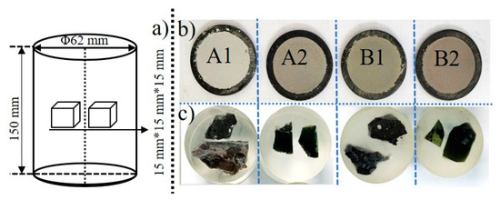
Figure 1.
The scheme of obtaining and the appearance of test samples: (a) schematic diagram of the metallographic specimen; (b) solid tundish covering flux samples ground into powder; (c) solid tundish covering flux samples broken into small blocks.
3. Results and Discussion
3.1. Inclusion Analysis
The changes in the type, number density and size of the inclusions in the steel before and after plasma heating were analyzed, and the effect of plasma heating on the cleanliness of the molten steel in the tundish was explored.
A1 denotes the group A samples before heating. The inclusions in the sample are mainly MnS and CaS inclusions and Al2O3-CaO-MgO, Al2O3-CaO-MgO-CaS, Al2O3-CaO and Al2O3-CaO-CaS composite inclusions. The morphology and energy-dispersive spectroscopy (EDS) maps of the inclusions are shown in Figure 2, where the shape of MnS is irregular. The Al2O3-CaO-MgO-CaS composite inclusions are mainly CaS-wrapped Al2O3-CaO-MgO.
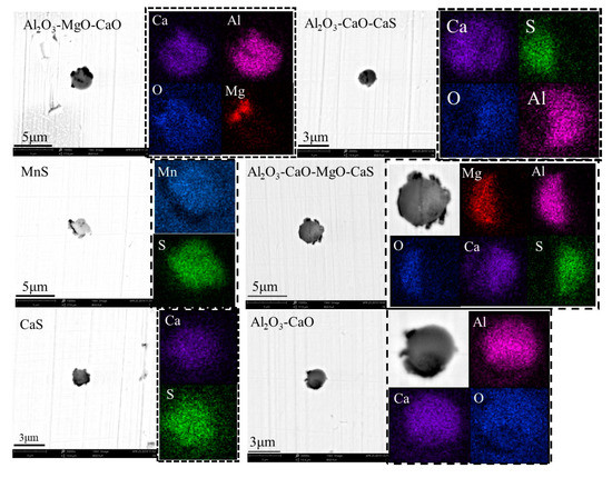
Figure 2.
SEM images and energy-dispersive spectroscopy (EDS) maps of the typical inclusions in A1.
Among them, the MnS inclusions are sized 2–3 μm and account for approximately 7% of the total number of inclusions; the Al2O3-CaO-MgO composite inclusions are sized 2–3 μm and account for approximately 13%; the Al2O3-CaO inclusions are sized 2–4 μm and account for 16%; the Al2O3-CaO-MgO-CaS inclusions are sized 2–4 μm and account for 38%; the Al2O3-CaS-CaO inclusions are sized 2–3 μm and account for 14%; and the CaS inclusions are sized approximately 2–3 μm and account for approximately 11%. The number density is 174.88 inclusions/mm2.
A2 is the group A samples after heating. The main types of inclusions in the sample are as follows: Al2O3-MgO-CaS inclusions, Al2O3-CaO-CaS inclusions and Al2O3-MgO-CaO inclusions. Typical morphology and surface scanning composition diagrams are shown in Figure 3. There are also a small number of Al2O3-CaO inclusions.
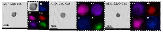
Figure 3.
SEM images and energy-dispersive spectroscopy (EDS) maps of the typical inclusions in A2.
In the sample, Al2O3-MgO-CaS inclusions account for approximately 46.25% of the total number of inclusions, Al2O3-MgO-CaO inclusions account for approximately 27.5%, Al2O3-CaO-CaS accounts for approximately 11.25% and Al2O3-CaO accounts for approximately 7.5%. The number density is 137.91 inclusions/mm2.
B1 is the group B samples before heating. The main types of inclusions in the sample are as follows: MnS inclusions, Al2O3-MgO inclusions, Al2O3-MgO-CaO inclusions and Al2O3-MgO-MnS-CaS inclusions. This sample also contains small numbers of Al2O3-MgO-CaS inclusions and MnS-Al2O3 inclusions. The typical morphology and surface scanning composition diagrams are shown in Figure 4.
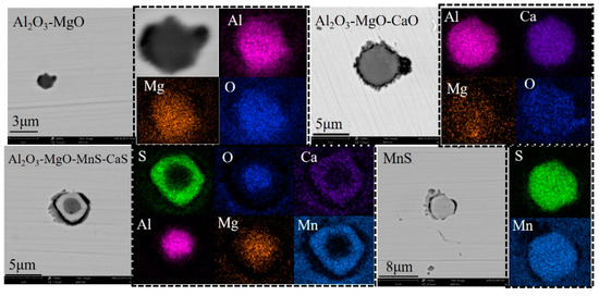
Figure 4.
SEM images and energy-dispersive spectroscopy (EDS) maps of the typical inclusions in B1.
Al2O3-MgO is sized approximately 1–2 μm and accounts for 19% of the total number of statistical inclusions; Al2O3-CaO-MgO is sized approximately 3–6 μm and accounts for approximately 25%; the MnS inclusions are sized approximately 2–5 μm and account for approximately 25%; the Al2O3-MgO-MnS-CaS inclusions are sized 2–5 μm and account for approximately 15%; the Al2O3-MgO-CaS inclusions are sized 1–2 μm and account for 8%; and the Al2O3-MnS inclusions are sized approximately 3–5 μm and account for approximately 8%. The number density is 173.17 inclusions/mm2.
B2 is the group B samples after heating. There are mainly two types of inclusions in the sample: Al2O3-MgO-CaS, CaS inclusions and a small number of MnS inclusions. The typical morphologies and surface scanning composition diagrams of the inclusions in the sample are shown in Figure 5.
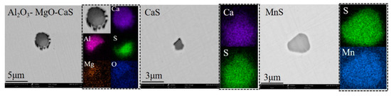
Figure 5.
SEM images and energy-dispersive spectroscopy (EDS) maps of the typical inclusions in B2.
The Al2O3-MgO-CaS inclusions in the sample are sized 1–3 μm and account for approximately 51% of the total number of inclusions; the CaS inclusions are sized 1–3 μm and account for 35%; and the MnS inclusions are sized approximately 2–4 μm and account for approximately 6%. The number density is 136.08 inclusions/mm2.
The overall characteristic changes in the inclusions before and after the two groups were heated are shown in Figure 6. After plasma heating, the inclusion number density decreases, the average size of the inclusions does not change much, fluctuating in the range of 1–2 μm, and the number of inclusion types decreases. Plasma heating has a certain control effect on the cleanliness of the molten steel in the tundish. Heating improves the flow field in the tundish, promotes the floating and removal of small-sized inclusions and reduces the number density of inclusions.
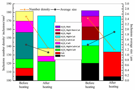
Figure 6.
Changes in the number density, size and type of inclusions before and after heating.
3.2. Tundish Covering Flux Analysis
3.2.1. Tundish Covering Flux Morphology Analysis
The appearance and morphology of the tundish covering fluxes before and after the two groups of plasma heating are shown in Figure 7. The appearance, texture and color of the tundish covering fluxes before and after plasma heating change significantly. The tundish covering fluxes before heating are loose in texture, and the surface is rougher and has many pores (red circles in Figure 7); the tundish covering fluxes after heating are denser, and the surface is smooth and somewhat similar to the glass state. This occurs because the temperature of the tundish covering flux is higher after plasma heating, and the cooling rate is faster, forming an amorphous state.
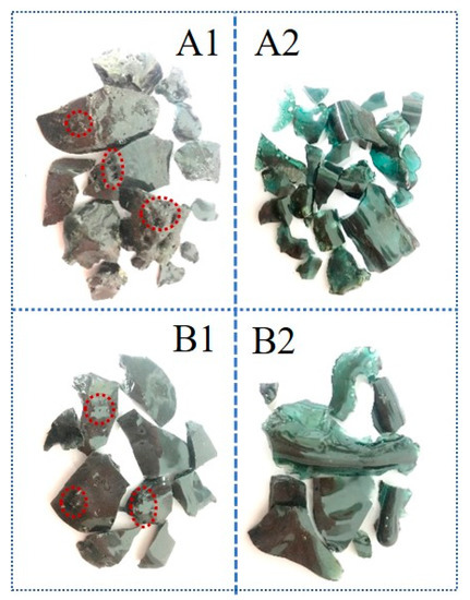
Figure 7.
Appearance and morphology of the tundish covering fluxes before and after plasma heating: A1, A group: before heating; A2, A group: after heating; B1, B group: before heating; B2, B group: after heating.
Figure 8 shows the micromorphology of the tundish covering fluxes samples of groups A and B before and after heating under an optical microscope. Under the light microscope, the micromorphologies of the two groups of samples before and after heating showed obvious differences. Before heating, uneven gray-black patches (indicated by the red arrow) are present in the sample, which are precipitated phases. After heating, the surface of the sample is smooth and dense, showing a microscopic uniform morphology, the existence of a crystalline phase is not observed and the entire sample surface is a glass phase.
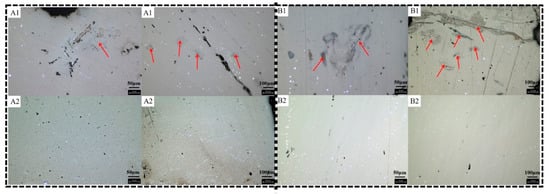
Figure 8.
Optical microscope images of the tundish covering fluxes before and after plasma heating: A1, A group: before heating; A2, A group: after heating; B1, B group: before heating; B2, B group: after heating.
3.2.2. Tundish Covering Flux Crystal Structure Analysis
The sampling positions of the two groups of tests are near the plasma heating cathode position. Figure 9 shows the XRD spectra of the two groups of tundish covering flux samples before and after heating. The high-temperature samples of molten tundish covering flux were taken from the tundish and then they were rapidly cooled in cold water. The XRD results show no obvious peaks for the heated tundish covering flux and a smooth curve near the diffraction angle 2 of 30°, which represents an amorphous phase [19]. This peak is mainly formed by diffuse scattering at a low diffraction angle from an amorphous phase in the sample. This is basically consistent with the conclusion that the macroscopic morphology is glassy. The temperature of the plasma arc column can reach 20,000 K, and the tundish covering flux sampling is near the plasma heating electrode. The temperature difference between the heated sample and the environment is large, the cooling rate is fast and the crystal growth time is short because the tundish covering flux samples were directly water-cooled after taking samples. The results are caused by insufficient growth, no crystal precipitation or less crystal precipitation. The peaks of the sample before heating are sharper. The crystalline phase of group A before heating (A1) is anorthite with formula Ca(Al2Si2)O8. Meanwhile, the crystalline phase of group B before heating (B1) is Ca-Tschermak’s pyroxene with formula CaAl2SiO6. The trends of the tundish covering flux before and after heating are basically the same for the two groups. In the heated sample, the temperature is higher, and there is basically no crystal precipitation during the cooling process, showing the characteristics of an amorphous state.
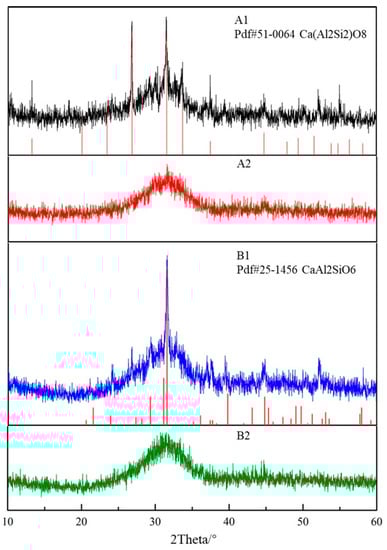
Figure 9.
XRD results for tundish covering flux samples before and after plasma heating: A1, A group: before heating; A2, A group: after heating; B1, B group: before heating; B2, B group: after heating.
3.2.3. Analysis of the Composition in the Liquid Phase Area of the Tundish Covering Flux
The phase diagram module of the FactSage thermodynamics software calculates the change in the liquid phase area of the tundish covering flux with temperature to characterize the melting liquid phase area of the tundish covering flux. Since the drawing of the pentad system phase diagram is very difficult, it is necessary to control two of the components and then construct the ternary phase diagram of the other three components. The calculation conditions are as follows: 1 atmosphere pressure, temperature range of 1300–1600 °C, temperature interval of 100 °C and oxygen partial pressure of 0.21 atm. The liquidus line projections of the tundish covering flux before and after the two heating tests are shown in Figure 10. Figure 10 is the pseudopentad system isothermal cross-sectional view of the tundish covering flux components before and after the two groups of plasma heating. The black solid figures in the figure represent the composition of the tundish covering flux sampled before and after heating. The figure shows that plasma heating has little effect on the liquid phase region of the tundish covering flux. In the range of lower heating power, plasma heating has no obvious effect on the low-melting point area of the tundish covering flux.
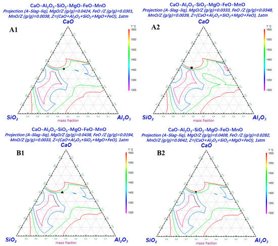
Figure 10.
The liquidus line projection of the tundish covering flux before and after plasma heating: A1, A group: before heating; A2, A group: after heating; B1, B group: before heating; B2, B group: after heating.
4. Conclusions
The plasma heating of the tundish can compensate for the temperature drop of the molten steel, and its ability to raise the temperature of the molten steel has also been confirmed, which can reduce the tapping temperature and realize low superheat pouring. However, due to the concentration of the plasma heating energy and the exchange of high energy, the effect on the cleanliness of the molten steel in the tundish and the properties of the tundish covering flux have not yet been studied. Therefore, this article explores the changes in the size, composition and number density of inclusions in the tundish before and after plasma heating and the influence of plasma heating on the evolution of the morphology, crystal structure and composition of the tundish covering flux. This can provide a theoretical basis for the development of the tundish plasma heating technology.
- Plasma heating improves the flow field of the molten steel in the tundish. The temperature field and the flow field affect each other and promote the floating of inclusions, especially small-sized inclusions. After heating, the types of inclusions are significantly reduced, and there are no significant changes in size.
- The morphology and crystal structure of the tundish covering flux are obviously different before and after plasma heating. After heating, the morphology is dense, and the surface is smooth. This shows that the uniformity of the microscopic morphology of tundish covering fluxes has been improved.
- The heated tundish covering flux has the characteristics of an amorphous state due to its fast cooling rate and large temperature difference. According to the FactSage analysis of the composition of the liquid phase of the tundish covering flux before and after heating, there are no significant changes in the two groups of samples.
Author Contributions
Conceptualization, M.Y. and S.Y.; methodology, M.Z.; software, S.C.; analysis, M.Y. and M.Z.; investigation, S.Y. and J.L.; writing—original draft preparation, M.Y.; writing—review and editing, J.L. and S.C. All authors have read and agreed to the published version of the manuscript.
Funding
This research was funded by the National Natural Science Foundation of China, grant numbers 51734003 and 51822401.
Conflicts of Interest
The authors declare no conflict of interest.
References
- Maher, I.B.; Pierre, F.; Emil, P. Thermal Plasmas: Fundamentals and Applications; Springer Science+Business Media: New York, NY, USA, 1994; pp. 1–10. [Google Scholar]
- Zhang, G.L.; Ao, L.; Hu, J.F. Applied Plasma Physics; Capital Normal University Press: Beijing, China, 2008; pp. 1–10. [Google Scholar]
- Weltmann, K.D.; Kolb, J.F.; Holub, M.; Uhrlandt, D.; Simek, M.; Ostrikov, K.K.; Hamaguchi, S.; Cvelbar, U.; Cernak, M.; Locke, B.; et al. The future for plasma science and technology. Plasma Process. Polym. 2019, 16, 1800118. [Google Scholar] [CrossRef]
- Fauchais, P.; Vardelle, A. Thermal plasmas. IEEE Trans. Plasma Sci. 1997, 25, 1258–1280. [Google Scholar] [CrossRef]
- Zhao, M.J.; Yang, S.F.; Li, J.S.; Xi, X.J.; Zhang, X.L.; Wang, Y.H.; Chen, Y.F. Effect of plasma heating on the molten steel in Tundish. In Materials Science and Technology 2019; Materials Science and Technology: Portland, OR, USA, 2019. [Google Scholar]
- Zuo, Q.W.; An, X.; Yang, J.B.; Cang, D.Q. Effects of over heat and casting speed on quality of GCr15 billet. Adv. Mater. Res. Front. Chem. Eng. Metall. Eng. Mater. III 2014, 997, 534–537. [Google Scholar] [CrossRef]
- Sahai, Y. Tundish technology for casting clean steel: A review. Metall. Mater. Trans. B 2016, 47, 2095–2106. [Google Scholar] [CrossRef]
- Wang, Q.; Qi, F.; Tsukihashi, F. Behavior of Non-metallic Inclusions in a Continuous Casting Tundish with Channel Type Induction Heating. ISIJ Int. 2014, 54, 2796–2805. [Google Scholar] [CrossRef]
- Vargas-Zamora, A.; Morales, R.D.; Dı́az-Cruz, M.; Palafox-Ramos, J.; Demedices, L.G. Heat and mass transfer of a convective-stratified flow in a trough type tundish. Int. J. Heat Mass Transfer. 2003, 46, 3029–3039. [Google Scholar] [CrossRef]
- Pak, Y.A.; Filippov, G.A.; Yusupov, D.I.; Tyuftyaev, A.S.; Isakaev, M.E.K.; Sarychev, B.A. Two-Strand Tundish with Chambers for Plasma Heating of Liquid Metal. Metallurgist 2014, 58, 672–676. [Google Scholar] [CrossRef]
- Fujimoto, H.; Tokunaga, H.; Iritani, H. A high-powered AC plasma torch for the arc heating of molten steel in the tundish. Plasma Chem. Plasma Process. 1994, 14, 361–382. [Google Scholar] [CrossRef]
- Kittaka, S.; Sato, T.; Wakida, S.; Miyashita, M. Twin-torch type tundish plasma heater “NS-plasma II” for continuous caster. Nippon Steel Tech. Rep. 2005, 92, 16–21. [Google Scholar]
- Barreto-Sandoval, J.J.; Hills, A.W.S.; Barrón-Meza, M.A.; Morales, R.D. Physical modelling of tundish plasma heating and its mathematical interpretation. ISIJ Int. 1996, 36, 1174–1183. [Google Scholar]
- Pan, J.; Hu, S.; Yang, L.; Chen, S. Numerical analysis of the heat transfer and material flow during keyhole plasma arc welding using a fully coupled tungsten–plasma–anode model. Acta Mater. 2016, 118, 221–229. [Google Scholar] [CrossRef]
- Li, L.; Li, B.; Liu, L.; Motoyama, Y. Numerical Modeling of Fluid Flow, Heat Transfer and Arc–Melt Interaction in Tungsten Inert Gas Welding. High Temp. Mater. Processes 2017, 36, 427–439. [Google Scholar] [CrossRef]
- Liao, M.R.; Chen, T.; Lv, W.J. Heating of the cathode with a conical tip by atmospheric-pressure arc plasma. Int. J. Numer. Methods Heat Fluid Flow 2019, 30, 2379–2395. [Google Scholar] [CrossRef]
- Douce, A.; Delalondre, C.; Biausser, H.; Guillot, J.B. Numerical Modelling of an Anodic Metal Bath Heated with an Argon Transferred Arc. ISIJ Int. 2003, 43, 1128–1135. [Google Scholar]
- Barrón-Meza, M.A.; De Barreto-Sandoval, J.; Morales, R.D. Physical and mathematical models of steel flow and heat transfer in a tundish heated by plasma. Metall. Mater. Trans. B 2000, 31, 63–74. [Google Scholar] [CrossRef]
- Wang, W.; Blazek, K.; Cramb, A. A Study of the Crystallization Behavior of a New Mold Flux Used in the Casting of Transformation-Induced-Plasticity Steels. Metall. Mater. Trans. B 2008, 39, 66–74. [Google Scholar] [CrossRef]
Publisher’s Note: MDPI stays neutral with regard to jurisdictional claims in published maps and institutional affiliations. |
© 2020 by the authors. Licensee MDPI, Basel, Switzerland. This article is an open access article distributed under the terms and conditions of the Creative Commons Attribution (CC BY) license (http://creativecommons.org/licenses/by/4.0/).