Influencing Microstructure of Vanadium Carbide Reinforced FeCrVC Hardfacing during Gas Metal Arc Welding


1
Production Technology, University of Applied Sciences Osnabrueck–Campus Lingen, 49808 Lingen, Germany
2
Department of Production Technology, Ilmenau University of Technology, 98693 Ilmenau, Germany
*
Author to whom correspondence should be addressed.
Metals 2020, 10(10), 1345; https://doi.org/10.3390/met10101345
Submission received: 11 September 2020
/
Revised: 28 September 2020
/
Accepted: 7 October 2020
/
Published: 8 October 2020
(This article belongs to the Special Issue Surface Engineering of Metals and Alloys)
Abstract
:Vanadium carbide (VC) reinforced FeCrVC hardfacings have become important to improve the lifetime of tools suffering abrasive and impact loads. This is because the microstructural properties of such hardfacings enable the primary VCs to act as obstacles against the penetrating abrasive. Because dilution is supposed to be the key issue influencing the precipitation behaviour of primary carbides during surfacing, the development of deposit welding processes exhibiting a reduced thermal impact, and hence lower dilution to the base material, is the primary focus of the current research. By inserting an additional hot wire in the melt, an approach was developed to separate the material and energy input during gas metal arc welding (GMAW), and hence realised low dilution claddings. The carbide content could be increased, and a grain refinement was observed compared with conventional GMAW. These effects could be attributed to both the reduced dilution and heterogeneous nucleation.
1. Introduction
To improve the wear resistance of tools subject to abrasion and impact, vanadium carbide (VC) reinforced Fe-based hardfacings have become increasingly important. According to Bouaifi et al., primarily precipitated VCs act as obstacles against the penetrating abrasive [1], whereby Wei et al. determined that an increasing amount and homogeneous distribution of hard phases improves the abrasive wear resistance [2]. Nishida et al. identified the distance between the hard phases as the primary influencing factor in improving the wear resistance, designated as the mean free path, λMFW [3]. It should be smaller than the mean diameter of the abrasive, dA, in order to achieve the maximum abrasive wear resistance. Additionally, VCs promote the grain refinement of the Fe-based alloy, leading to an increase in the material toughness, and hence impact wear resistance [4].
Different kinds of welding processes are applied as surfacing techniques, such as laser cladding, plasma transferred arc welding, and gas metal arc welding (GMAW) [5]. The aim is to ensure deposition rates of several kilograms per hour and a metallurgical bonding with the base material. In this context, the dilution rate is known to play a key role. Borle et al. determined that an increase in the dilution rate causes a percentage decrease in the carbide-forming elements in the melt, which was investigated for the Fe-Cr-C alloy system [6]. As a consequence, the primary carbide content and the wear resistance decreased. Bucheley et al. proposed a multi-layer technique to compensate for the influence of dilution on the chemical composition of the melt [7].
For this reason, the development of highly productive welding processes that ensure low dilution rates has become increasingly important. Current efforts are particularly focused on GMAW, because the process offers a high degree of mechanization and a controlled feeding of the consumable GMAW electrode [8]. The disadvantage of GMAW, however, lies in the direct correlation between the material and energy input; thus, an increase in the deposition rate immediately corresponds to an increase in dilution of the base material. This was demonstrated by Badisch et al. for Ni-based alloys [9]. Sorour et al. obtained comparable effects for Fe-based hardfacing alloys [10]. The application of an additional hot wire (HW-GMAW) appears to be highly promising in improving the economic efficiency of GMAW. In this context, the separate adjustment of the material and energy input could be proved, resulting in the deposition-independent realisation of low-dilution hardfacings [11]. Further investigations demonstrated that the thermally induced degradation of fused tungsten carbides could be reduced [12], and a more homogeneous hard phase distribution was achieved compared with conventional GMAW [13]. Investigations on FeCrC hardfacing demonstrated that HW-GMAW enables the formation of primary M7C3 carbides in single-layer welds, regardless of the deposition rate [14]. Under this condition, the influence of VC reinforced Fe-based hardfacings on the microstructure is unknown. Hence, the purpose of this study is to investigate the influence of an additional hot wire on the precipitation behaviour of VCs and the microstructural properties during GMAW.
2. Materials and Methods
2.1. Welding Equipment and Materials
The experiments were performed with a GMAW power source Alpha Q 552 (EWM AG, Mündersbach, Germany). As the hot wire power supply, a Triton 260 TGD (Dinse GmbH, Hamburg, Germany) was used for resistance heating. The maximum voltage was limited to 10 V in order to avoid spontaneous arcing [15]. The experimental set-up of hot wire assisted GMAW (HW-GMAW) is schematically shown in Figure 1. The hot wire was fed in the melt pool at an angle of ~40°, relative to the substrate material. The GMAW parameter set-up remained constant in order to provide a stable process behaviour in spray arc mode. The wire feed rate, vGMAW, was 5 m/min at a welding voltage, UGMAW, of 29 V. The welding speed, vS, was 300 mm/min. Ar mixed with 30% He was used as the protection gas. The welding torch and hot wire nozzle were manipulated by means of a KUKA robot KR 150. The welding tests were performed in stringer bead mode.
Unalloyed steel, S355 J2+N, with dimensions of 5 × 50 × 120 mm3, served as the substrate material for a defined weld seam length of 100 mm. Before welding tests, the substrate surface was sandblasted, cleaned with isopropanol, and finally fixed on a water-cooled clamping tool in order to ensure reproducible testing conditions. As the welding material, a FeCrVC flux-cored filler wire (ø 1.2 mm) was used with a specified V-content of 12 wt.% and C-content of 2.7 wt.% (see Table 1). The filler material was designated by FeV12 in the following.
2.2. Electrical Welding Parameters
The welding current, IGMAW, and welding voltage, UGMAW, as well as the hot wire current, IHW, and hot wire voltage, UHW, were detected with an oscilloscope Dewe 800 (Dewetron, Grambach, Austria) by measuring the analogous output signals of the welding equipment at a frequency of 50 kHz. The arithmetic mean values of the recorded current and voltage profiles were used to calculate the process powers PGMAW, PHW, and PGMAW+HW according to Equations (1) and (2). PGMAW+HW was finally divided by the deposited mass of filler material, mGMAW+HW, in order to consider the material input via both the consumable electrode and the hot wire. The value was designated as the specific process power, PS, see Equation (3).
U-I measurements (Dewetron, Grambach, Austria) were additionally performed to monitor the hot wire feeding conditions. It was ensured that the tip of the hot wire touched the melt pool surface consistently. A premature dripping of the hot wire tip before entering the melt pool was indicated by interruptions of the current profile and could thus be avoided. Hence, the hot wire current, IHW, was always adjusted to the applied hot wire feed speed, vHW, in order to maintain contact of the filler wire with the melt pool.
2.3. Metallographic Investigations and Image Processing
For metallographic investigations, three cross sections per sample were extracted at a weld seam length of 40, 50, and 60 mm and finally ground as well as polished in a multi-stage procedure. Macroscopically, the dilution rate, A, was of interest; see Figure 2.
The visualization of the microstructure and carbides was performed by means of light microscopic and scanning electron microscopic investigations. Regarding the light microscopic examinations, HF/AgNO3 etching solution was applied. The etching solution consisted of 2 mL HF, 5 g AgNO3, and 100 mL H2O. Voort described the effect of the etching solution on the microstructural appearance [16]. Martensite is visible by a dark colouring, whereas VCs and retained austenite appear white.
Regarding scanning electron microscopic investigations, a backscatter electron detector (BSE) was used (Thermo Fisher Scientific, Waltham, MA, USA). By applying the BSE, the obtained element contrast of the images enabled a first estimation with respect to the material composition. A dark colouring could be assigned to light elements and a bright colouring to heavy elements. Chemical phase compositions were determined by means of electron dispersive X-ray analysis (Thermo Fisher Scientific, Waltham, MA, USA) at an accelerating voltage of 30 keV. The elementary influence of adjacent phases was considered because of the stimulation of the valence electrons close to the measuring position.
The global chemical composition of the weld seam was determined by means of X-ray fluorescence (XRF, Helmut Fischer GmbH, Sindelfingen, Germany) at a spot diameter of 0.3 mm. The measurements were performed on the metallographically prepared cross sections, considering the elements Fe, Cr, and V.
A MATLAB-based image processing tool (The MathWorks, Natick, MA, USA) was applied to determine the percentage of VCs in the matrix material; this enabled the selective detection of pixels with different brightness intensities. BSE images with a magnification of 500 were used; see Figure 3.
3. Results
3.1. Macroscopic Weld Seam Characteristics and XRF Measurements
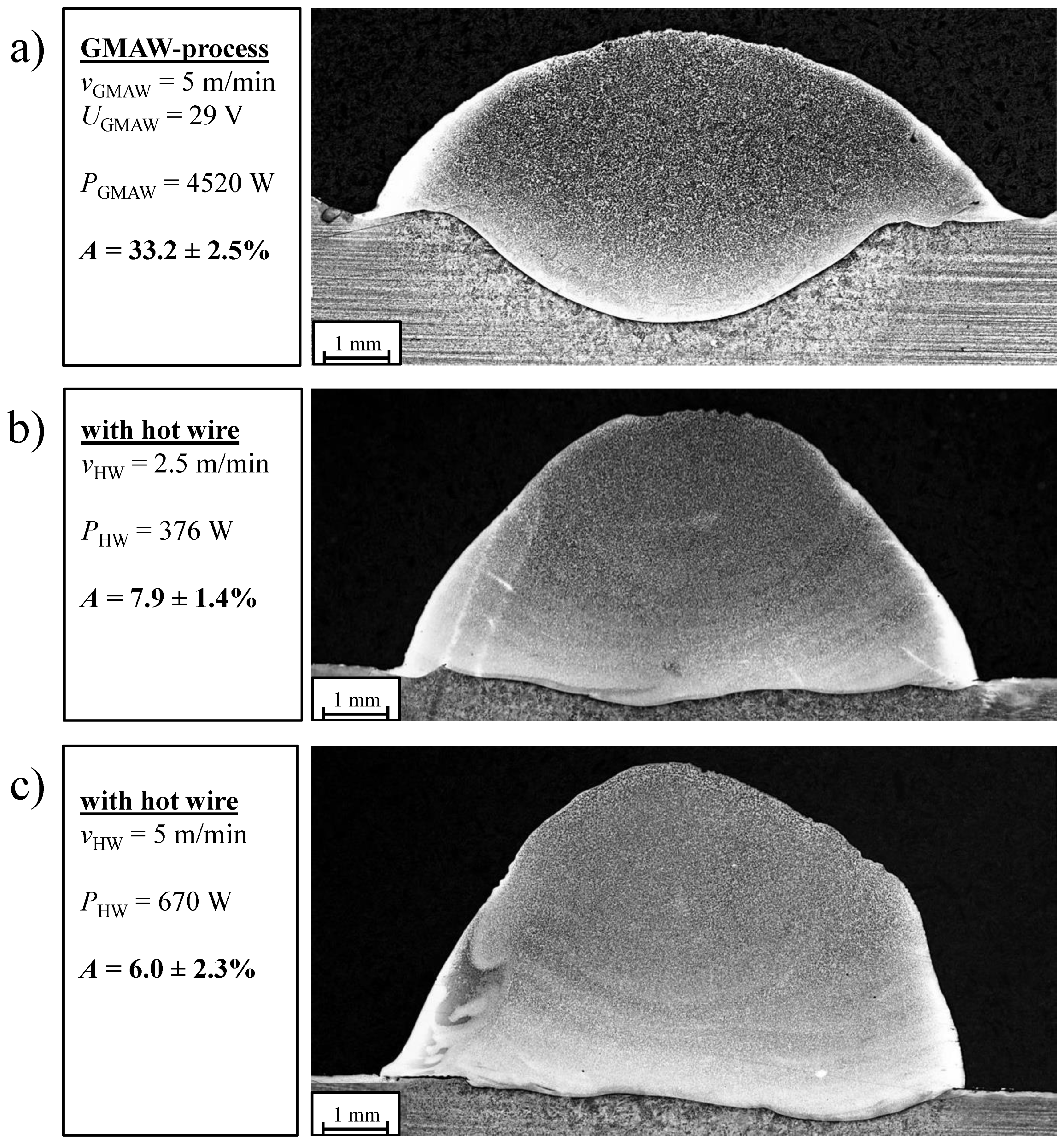
The influence of the additional hot wire during GMAW of FeV12 is depicted in Figure 4. The conventional GMAW with a wire feed rate, vGMAW, of 5 m/min and a welding voltage, UGMAW, of 29 V serves as a reference. According to Figure 4a, conventional GMAW is characterised by a dilution rate, A, of ~33%. A steady increase in the material input via the hot wire results in a decrease in the dilution rate, A, from ~33 to ~6%; see Figure 4b,c. At the same time, the deposition rate doubles.
The reduced dilution rate can be correlated with the decrease in the specific process power, PS. Because the hot wire power, PHW, equals 15% of PGMAW, so as to fuse the filler wire at wire feed speeds, vGMAW and vHW, of 5 m/min, the specific process power, PS, is reduced from ~400 to ~215 W/g; see Figure 5.
An XRF element scan was performed at the cross section along the melt bead height, according to Section 2.3, to determine the influence of the decreasing dilution rate, A, on the chemical composition of the hardfacing. Figure 6 shows that the dilution has an immediate influence on the element composition. The average percentage of V and Cr increases from ~6 to ~10 wt.%. Furthermore, the element distribution, displayed in the example of V, is uniform along the melt bead height. Because of the increase in the amount of carbide-forming elements, a change in the microstructural properties is expected.
3.2. Basic Microstructural Investigations
Characterisation of the basic microstructural features of FeV12 was first necessary in order to investigate the influence of the additional hot wire on the microstructural properties. Figure 7 describes the microstructural characteristics on the basis of metallographic (Figure 7a) and electron microscopic (Figure 7b) examinations.
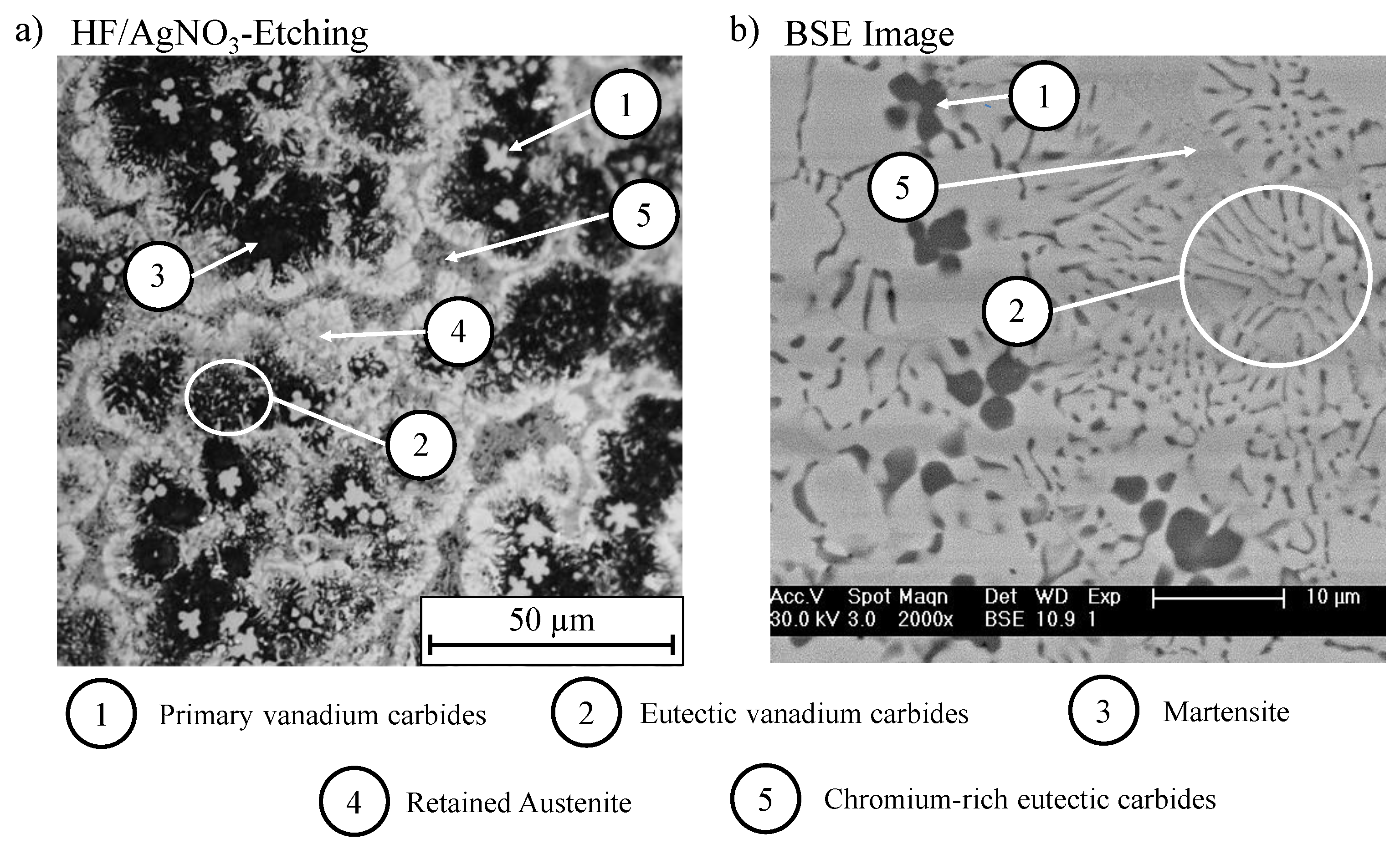
Using HF/AgNO3 etching solution, primary VCs are clearly indicated by their white contrast and round shape; see Figure 7a, Position 1 (Pos. 1). Additionally, lamellar precipitations with a star-like solidification structure and comparable colouring are apparent, indicating eutectic VCs; see Figure 7a (Pos. 2). Primary and eutectic VCs are clearly silhouetted against the surrounding dark phase, indicating martensite; see Figure 7a (Pos. 3). The white non-etched regions in the matrix material are assumed to be retained austenite; see Figure 7a (Pos. 4). A slightly darker phase can be distinguished from the white coloured retained austenite, which is assumed to be Cr-rich carbides; see Figure 7a (Pos. 5).
Complementary investigations were performed by means of BSE imaging and EDX. Figure 7b shows that all microstructural features are in accordance with the light microscopic observations. The detected element composition of the different phases is listed in Table 2. Position 1 shows the highest V-content of ~62 wt.%; see Table 2 (Pos. 1). This affirms the precipitation of primary VCs with an average size of 4 µm; see Figure 7b (Pos. 1). The eutectic VCs are characterised by an element contrast comparable with the primary precipitates and exhibit a lamellar solidification structure; see Figure 7b (Pos. 2). The corresponding V-content of ~8.5 wt.% is comparatively small because of the influence of adjacent phases during EDX measurements; see Table 2 (Pos. 2). Cr-rich carbides show the highest amount of detected Cr (~20 wt.%)—see Table 2 (Pos. 5)—and display a fine lamellar eutectic microstructure; see Figure 7b (Pos. 5). BSE images and EDX analyses were not able to differentiate between martensite and retained austenite.
3.3. Influence of An Additional Hot Wire on the Microstructure
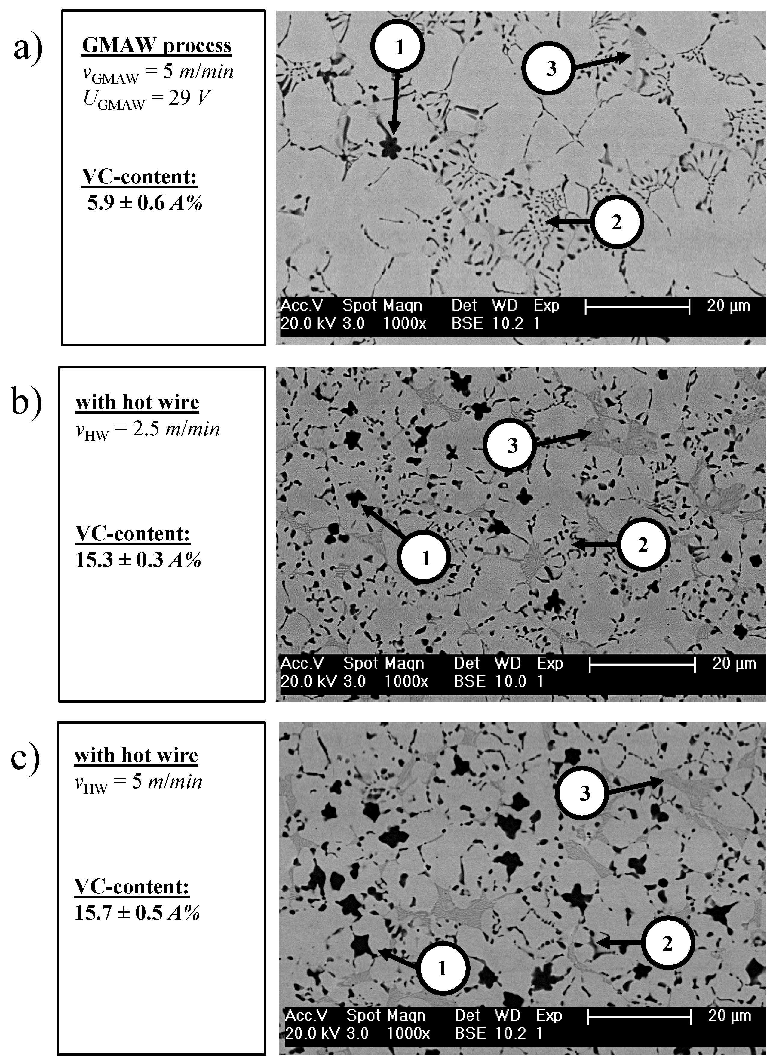
Figure 8 depicts the influence of an additional hot wire on the carbide morphology of FeV12 hardfacings. The microstructure of conventional GMAW hardfacings consists of a relatively small amount of primary VCs (Figure 8a, Pos. 1) and eutectic Cr-rich carbides (Figure 8a, Pos. 3). By applying an additional hot wire, the amount of primary VCs (Pos. 1) and eutectic Cr-rich carbides (Pos. 3) increases; see Figure 8b,c. At the same time, the amount of eutectic VCs (Pos. 2) decreases.
An image processing tool was used to determine the amount of VCs depending on the process parameters, according to Section 2.3, whereby a differentiation between the eutectic and primary carbides was not possible because of the similar element contrast. It was determined that an increasing hot-wire assisted material input immediately corresponds with increasing VC content from ~6 to ~15.7 A%; see Figure 8a–c. Hereby, the percentage increase in VC is dedicated to the primary precipitates.
The increasing VC content directly corresponds to a grain refinement of the matrix material as well as increase in the size of the primary VC; see Figure 8a–c. Hereby, BSE images show that the last-named effect is due to a star-like agglomeration of VCs in the melt; see Figure 9.
To summarise the macro- and microscopic features, it must be assumed that the increasing carbide content is primarily influenced by the decreasing dilution rate, A, and hence the percentage increase of carbide-forming elements in the melt. In order to fortify this assumption, a three-layer GMAW hardfacing was realised to compensate for dilution effects and enable an immediate comparison between GMAW and HW-GMAW. In fact, the single-layer HW-GMAW and the three-layer GMAW hardfacing exhibit a comparable vanadium content of ~10.5 wt.%. However, grain refinement effects and the VC content are considerably more pronounced for the single-layer HW-GMAW hardfacing; compare Figure 10a,b.
This proves that the microstructural features of FeV12 are not only dependent on the dilution rate and element concentration in the melt, but also influenced by a direct impact on the temperature–time regime because of the hot wire. This will be discussed in detail in Section 4.
4. Discussion
4.1. Separation of the Energy and Material Input
The results demonstrate that an additional hot wire during GMAW causes an improvement of the surfacing quality. Because of the separate adjustments of the material and energy input, independent control of the deposition and dilution rate was made possible. The deposition rate doubled from ~2.14 to ~4.28 kg/h, whereas the dilution rate, A, could be reduced from ~33 to ~6%; see Figure 4. It was determined that the reduction in dilution correlates with a decrease in specific process power, PS, of ~53%; see Figure 5. However, the actual reason for the reduced dilution rate, A, is the decreasing melt bead temperature. The decrease in melt bead temperature is attributed to the comparatively colder hot wire inserted in the melt, which was already demonstrated for Ni-based alloys in [17].
The decreasing dilution rate, A, and rising percentage of carbide forming elements, such as Cr, V, and C (see Figure 6), have a direct impact on the metallurgical properties of the quaternary alloy FeV12. However, the solidification morphology of FeV12 during welding is insufficiently described in the scientific literature. Consequently, it was required that the basic microstructural properties be identified and understood first.
4.2. Microstructural Features of FeV12
The microstructure consists of round-shaped VCs, which begin to precipitate primarily at a temperature of 2656 °C according to [18]; see Figure 7a (Pos. 1). From Wei et al., it is known that primary VCs homogeneously precipitate at a V-content of 8.15–10.2 wt.% and a C-content of 2.7–3.15 wt.% [2]. In the present case, the beginning precipitation of primary VCs was observed for a vanadium content of ~6 wt.%; see Figure 7a and Figure 8a. The advancing solidification of the melt finally results in the formation of eutectic VCs. According to [18], the approximate melting or solidification temperature of eutectic VCs is 1650 °C. Hereby, primary VCs act as heterogeneous nuclei, explaining the star-like solidification of the eutectic precipitations; see Figure 7a (Pos. 2). Regarding temperatures beneath the solidus line, Cr-rich eutectic carbides begin to precipitate—see Figure 7a (Pos. 5)—whereby Lee et al. proposed the stoichiometric composition, M23C6 [19].
The matrix of FeV12 consists of martensite and retained austenite; see Figure 7a (Pos. 3 and 4). Hence, the matrix does not completely transform to martensite, because a portion remains metastable austenite. According to [20], this circumstance is based on the high C-content of FeV12, reducing the martensite initiation temperature, MS, to below room temperature. The martensitic zones are particularly adjacent to the precipitated carbides, reducing the local amount of C in the Fe-based matrix. As a consequence, the local decrease in C finally results in an increase in the martensite initiation temperature, MS. This is the reason for the preferential formation of martensite close to the carbide boundary surface.
4.3. Microstructural Modifications and Driving Forces
The microstructure was significantly influenced by means of an additional hot wire. Hereby, an increasing material input via the hot wire causes an increase in the primary VC content; see Figure 8. One reason is the increasing amount of carbide-forming elements in the melt due to the reduced dilution, A. According to [18], the hypereutectic solidification range increases, promoting the precipitation of primary precipitates. Similarly, the amount of eutectic VC decreases, as a certain amount of V and C is detracted from the melt.
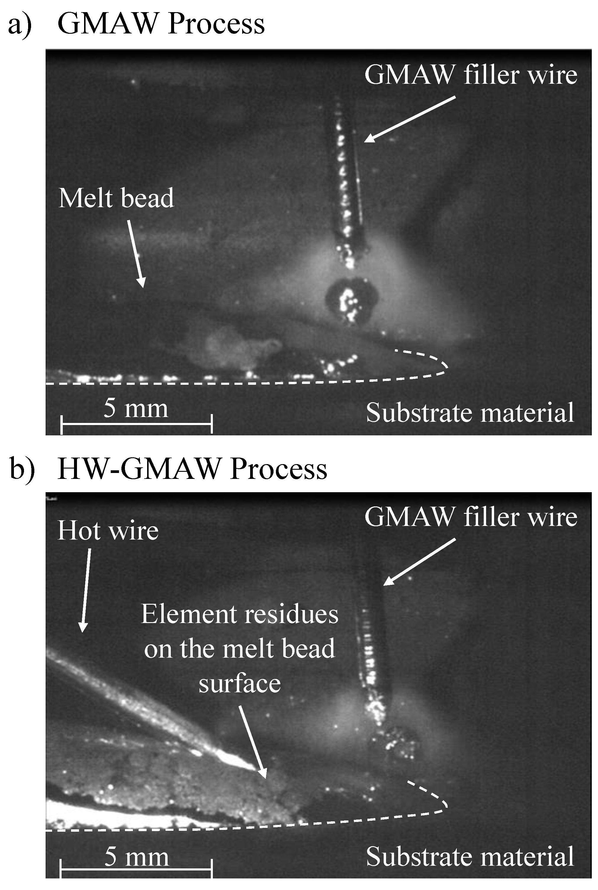
The dilution rate, A, is not the only parameter that influences the microstructural properties and the precipitation behaviour. This can be demonstrated by the comparison between a single-layer HW-GMAW and a multi-layer GMAW hardfacing; see Figure 9. Despite a comparable element composition, the single-layer HW-GMAW hardfacing exhibits a higher amount of primary VCs and a fine-grained microstructure. Hence, heterogeneous nucleation should also be considered in order to describe the influence of an additional filler wire during GMAW. The driving force for heterogeneous nucleation is probably based on two effects. First, the hot wire is directly fed into the melt pool and is not exposed to the high arc temperatures. As a result, the thermal impact on the alloying elements is reduced, because the melt temperature is 1000 °C lower compared with the temperature of the detaching droplet [21]. Second, the melt bead temperatures of HW-GMAW are lower compared with conventional GMAW because of the impact of the cold hot wire inserted in the melt bead [17]. Both conditions promote the increasing formation of a stable nucleus in the melt, whereby the existence of non-molten element residues on the melt bead surface can be visualised by means of high-velocity imaging; see Figure 11a,b.
Whereas the melt bead of conventional GMAW visually exhibits a complete melting of the filler wire, HW-GMAW reveals elemental residues on the melt bead surface. These residues act as heterogeneous nuclei, promoting the formation of primary carbides and grain refinement.
A further microstructural particularity of the single-layer HW-GMAW hardfacing is the increased size of primary VC compared with multi-layer GMAW welding; compare Figure 10a,b. This is due to agglomerations (see Figure 9), whereby the effect cannot be simply explained by a decrease in dilution and heterogeneous nucleation. It is known that the melt bead size and length increase by inserting an additional hot wire in the GMAW melt pool [22]. Consequently, primary VCs are provided more time for the diffusion processes in the melt, promoting the agglomeration of these precipitates.
The observed microstructural changes did not display an impact on the macro-hardness, which consistently varied between 750 and 850 HV2. In this context, Keränen illustrated that the material hardness does not serve as a reliable indicator for predicting the wear resistance [23]. However, it is assumed that the increasing amount of primary VCs indicates an enhanced abrasive wear resistance, because the mean free path, λMFP, decreases. Furthermore, the observed grain refinement implies an improvement in toughness with respect to impact loads. Thorough investigations will be performed concerning wear behaviour under abrasion and impact loads, as well as a combination of both, in order to obtain an understanding of the microstructural influence on wear resistance.
5. Conclusions
The investigations demonstrate that HW-GMAW is a promising welding strategy for hardfacing applications. Because of the separate adjustment of the energy and material input, the deposition and dilution rate can be controlled independently. In comparison with conventional GMAW, the dilution rate could be reduced from ~33 to ~6%, whereas the deposition rate doubled from ~2.14 to ~4.28 kg/h.
Furthermore, the microstructural features could be modified significantly. The size and content of primary VCs could be increased. In addition, grain refinement of the matrix could be observed, which comprised martensite and retained austenite. Hereby, the microstructural modifications of HW-GMAW hardfacings are principally based on two effects: the increasing amount of carbide-forming elements due to the reduced dilution, and the reduced thermal impact of alloying elements promoting heterogeneous nucleation.
As a next step, the influence of the microstructure and primary carbide content on the abrasive and impact wear behaviour will be examined. It is assumed that the wear behaviour under abrasion and impact will be improved compared with GMAW. This must be proven in terms of further investigations.
Author Contributions
K.G. has written the original draft. J.P.B. has reviewed and edited the submission. Both authors have read and agreed to the published version of the manuscript.
Funding
This research project (IGF-Number 18.008 BR/DVS-Nr. 03.119) was funded by the German Research Association on Welding and Allied Processes (DVS) and sponsored by the German Ministry of Economy and Energy. The authors would like to thank these organisations for their support.
Acknowledgments
The authors extend heartfelt thanks to EWM AG for their support with the welding equipment. The authors would also like to thank Maik Rosenberger and Chen Zhang for providing the image processing software tool.
Conflicts of Interest
The authors declare no conflict of interest.
References
- Bouaifi, B.; Bartzsch, J.; Gebert, A.; Heinze, H. Untersuchungen zum Plasma-Auftragschweißen von verschleißfesten Hartstoffschichten mit Vanadium-carbiden. Investigations on PTA-surfacing of wear resistant layers reinforced with vanadium carbides. Schweiss. Schneid. 1997, 49, 213–219. [Google Scholar]
- Wei, S.; Zhu, J.; Xu, L. Research on wear resistance on high speed steel with high vanadium content. Mater. Sci. Eng. A 2005, 404, 138–145. [Google Scholar] [CrossRef]
- Nishida, M.; Araki, T.; Fujita, H. Effect of TiC-Cr3C2 particles content on abrasive resistance of Co-base overlay weld alloy. Trans. Jpn. Weld. Soc. 1993, 24, 107–112. [Google Scholar]
- Lampman, J.R.; Peters, A.T. Ferroalloys and Other Additives to Liquid Iron and Steel: A Symposium; ASTM International: Baltimore, MD, USA, 1981. [Google Scholar]
- Kvidahl, L.G. The Practical Reference Guide for Hardfacing; American Welding Society: Miami, FL, USA, 2002. [Google Scholar]
- Borle, S.D.; le Gall, I.; Mendez, P.F. Primary chromium carbide fraction control with variable polarity SAW. Weld. J. 2015, 94, 1–7. [Google Scholar]
- Bucheley, M.F.; Gutierrez, J.C.; Leon, L.M.; Toro, A. The effect of micro-structure on abrasive wear of hardfacing alloys. Wear 2005, 259, 52–61. [Google Scholar] [CrossRef]
- Kah, P.; Suorante, R.; Martikainen, J. Advanced gas metal arc welding processes. Int. J. Adv. Manuf. Technol. 2013, 67, 655–674. [Google Scholar] [CrossRef]
- Badisch, E.; Kirchgassner, M. Influence of welding parameters on microstructure and wear behaviour of a typical NiCrBSi hardfacing alloy reinforced with tungsten carbide. Surf. Coat. Technol. 2008, 202, 6016–6022. [Google Scholar] [CrossRef]
- Sorour, A.A.; Chronik, R.R.; Gauvin, R.; Jung, I.H.; Brochu, M. Understanding the solidification and microstructure evolution during CSC-MIG welding of Fe-Cr-B-based alloy. Mater. Charact. 2013, 86, 127–138. [Google Scholar] [CrossRef]
- Günther, K.; Schulze, R.; Bergmann, J.P. Hot wire assisted gas metal arc welding of Ni-TC hardfacings. Weld. J. 2013, 12, 382–387. [Google Scholar]
- Günther, K.; Bergmann, J.P.; Suchodoll, D. Hot wire-assisted gas metal arc welding of hypereutectic FeCrC hardfacing alloys: Microstructure and wear properties. Surf. Coat. Technol. 2018, 334, 420–428. [Google Scholar] [CrossRef]
- Günther, K.; Bergmann, J.P.; Zhang, C.; Rosenberger, M.; Notni, G. Hot wire-assisted gas metal arc welding of Ni-based hardfacing. Weld. J. 2018, 97, 99–107. [Google Scholar]
- Guest, S.D. Depositing Ni-WC Wear Resistant Overlays with Hot-Wire Assist Technology. Ph.D. Thesis, University of Alberta, Edmonton, AB, Canada, 2014. [Google Scholar]
- Hori, K.; Watanabe, H.; Myobo, T. Development of hot wire TIG welding methods using pulsed current to heat filler wire—Research on pulse heated hot wire TIG welding processes. Weld. Int. 2003, 18, 456–468. [Google Scholar] [CrossRef]
- Voort, G.F.V. Applied Metallography; Van Nostrand Reinhold Company: New York, NY, USA, 1986. [Google Scholar]
- Füssel, U.; Bergmann, J.P. Tandem-GMAW with an Additionally Inserted Filler Wire in Order to Realize Graded Wear Resistant Hardfacings; Report 18.008 BR of the AiF Reseach Association; AiF Reseach Association: Dresden, Germany, 2016. [Google Scholar]
- Okamoto, H.; Schlesinger, M.E.; Mueller, E.M. Alloy phase diagrams. In A.S.M. Handbook; ASM International: Novelty, OH, USA, 1992; Volume 3. [Google Scholar]
- Lee, B.; Lee, D. A thermodynamic evaluation of the Fe-Cr-V-C system. J. Phase Equilib. 1992, 13, 349–364. [Google Scholar] [CrossRef]
- Filipovic, M.; Romhanji, E.; Kamberovic, Z.; Korac, M. Matrix microstructure and its microanalysis of consitutent phases in as-cast Fe-Cr-C-V alloys. Mater. Trans. 2009, 50, 2488–2492. [Google Scholar] [CrossRef] [Green Version]
- Siewert, E. Experimental Analyses of the Metal Transfer in Pulsed GMAW. Ph.D. Thesis, Universität der Bundeswehr München, München, Germany, 2014. [Google Scholar]
- Günther, K.; Schröder, T.; Bergmann, J.P. AC hot wire assisted gas metal arc welding—Potentials and challenges. In Proceedings of the Welding Conference “Große Schweißtechnische Tagung”, Berlin, Germany, 15–16 September 2014. [Google Scholar]
- Keränen, M. Effect of Welding Parameters of Plasma Transferred Arc Welding Method on Abrasive Wear Resistance of 12V Tool Steel Deposit. Ph.D. Thesis, Aalto University, Espoo, Finland, 2010. [Google Scholar]
Figure 1.
Schematic drawing of the experimental set-up. GMAW, gas metal arc welding.
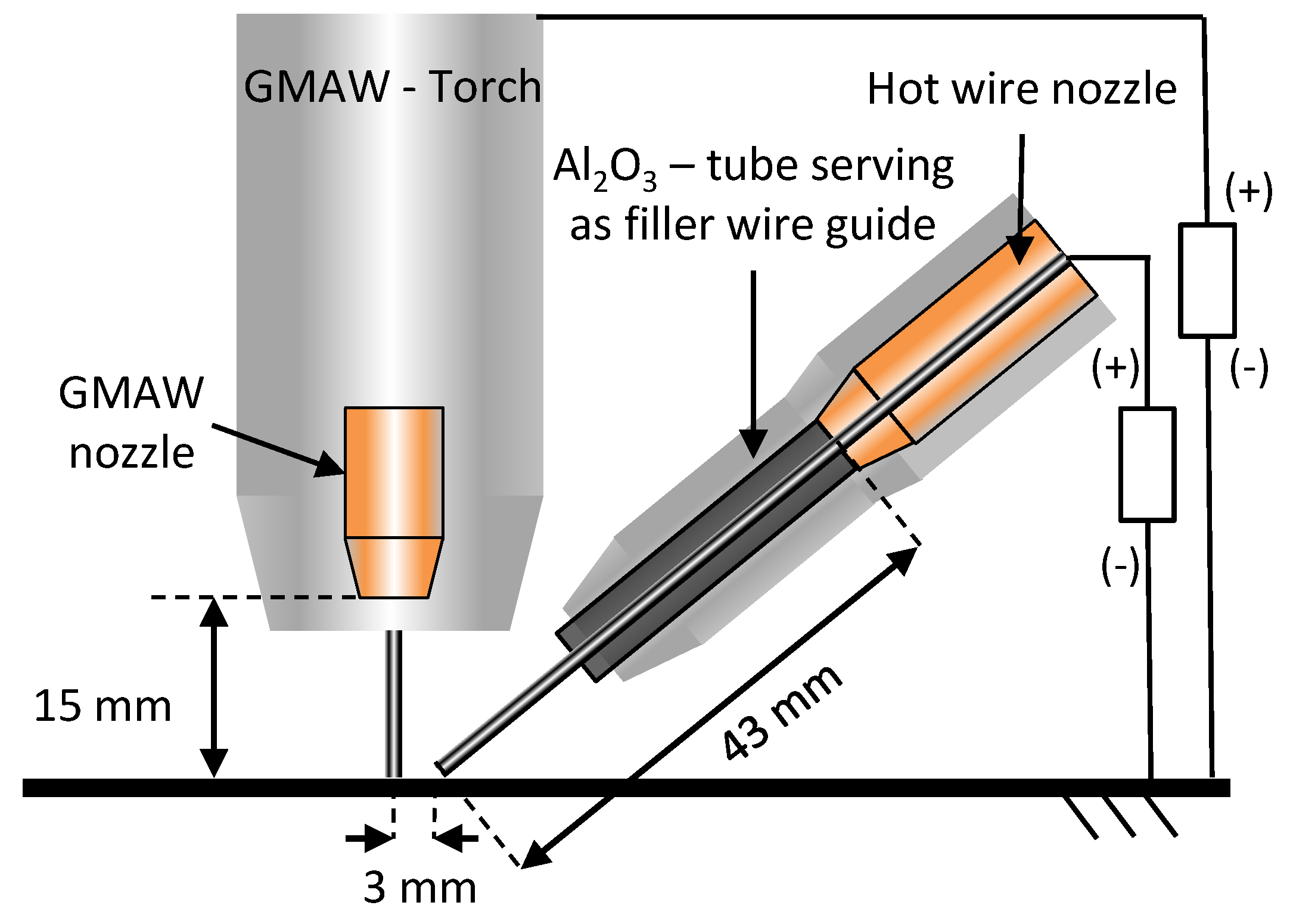
Figure 2.
Definition of the dilution rate A.
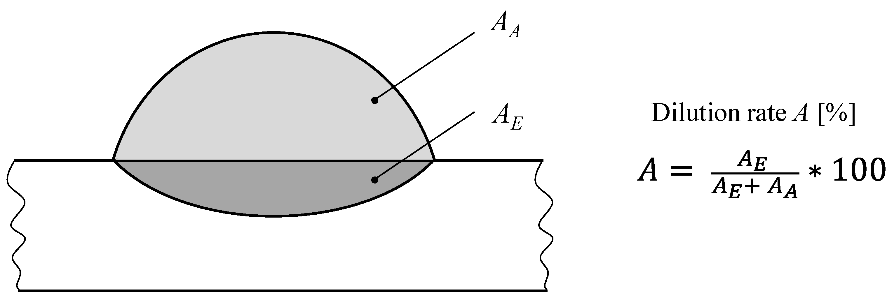
Figure 3.
Backscatter electron detector (BSE) images of the microstructure (a) before and (b) after image processing.
Figure 3.
Backscatter electron detector (BSE) images of the microstructure (a) before and (b) after image processing.
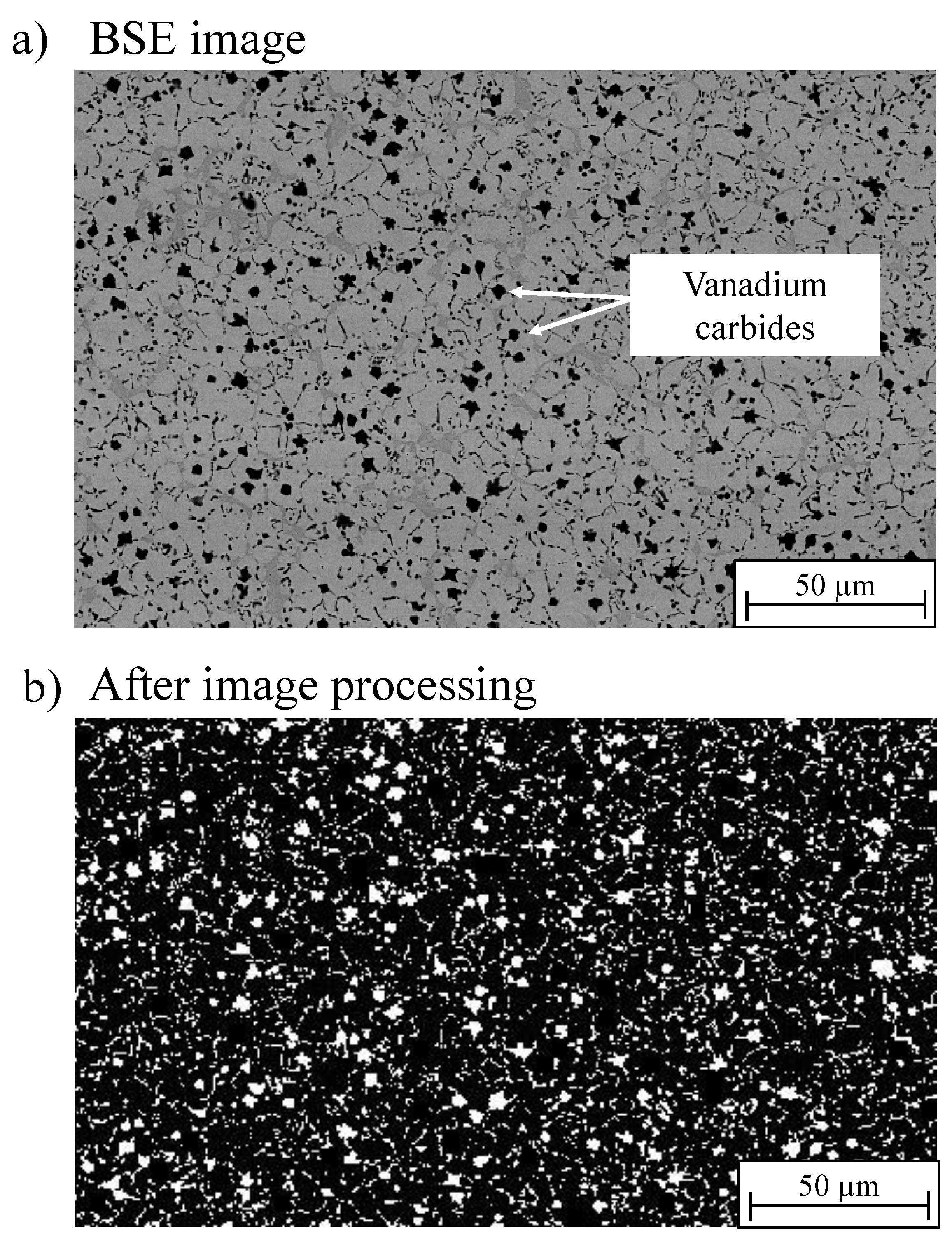
Figure 4.
Influence of an additional hot wire on the dilution rate, A, and macroscopic melt bead features during gas metal arc welding (GMAW). (a) Cross section of conventional GMAW (vGMAW = 5 m/min) with a dilution rate A of 7.9% (b) by applying an additional hot wire (vHW = 2,5 m/min), the dilution rate A decreased to 7.9%, (c) by applying an additional hot wire (vHW = 5 m/min), the dilution rate A decreased to 6.0%.

Figure 5.
Influence of an additional hot wire (HW) on the process power, PGMAW+HW, and specific process power, PS, during GMAW.
Figure 5.
Influence of an additional hot wire (HW) on the process power, PGMAW+HW, and specific process power, PS, during GMAW.
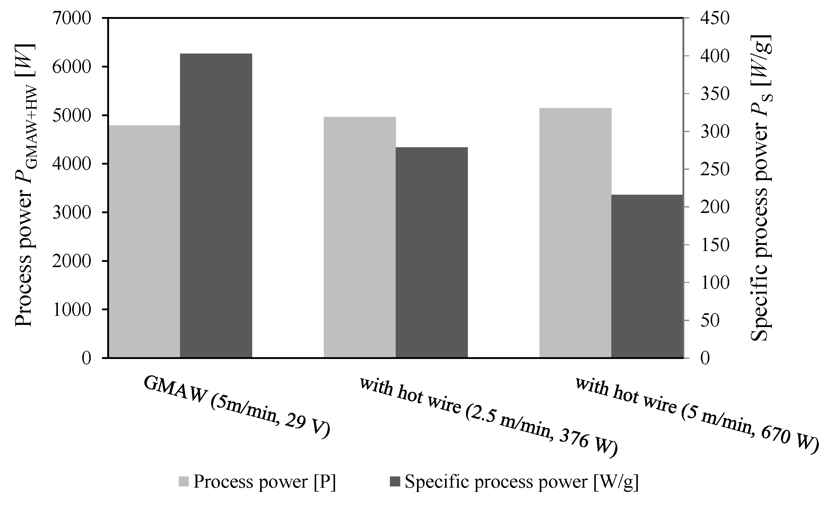
Figure 6.
Percentage of V, Cr, and Fe in the hardfacing depending on the hot wire assisted material input.
Figure 6.
Percentage of V, Cr, and Fe in the hardfacing depending on the hot wire assisted material input.
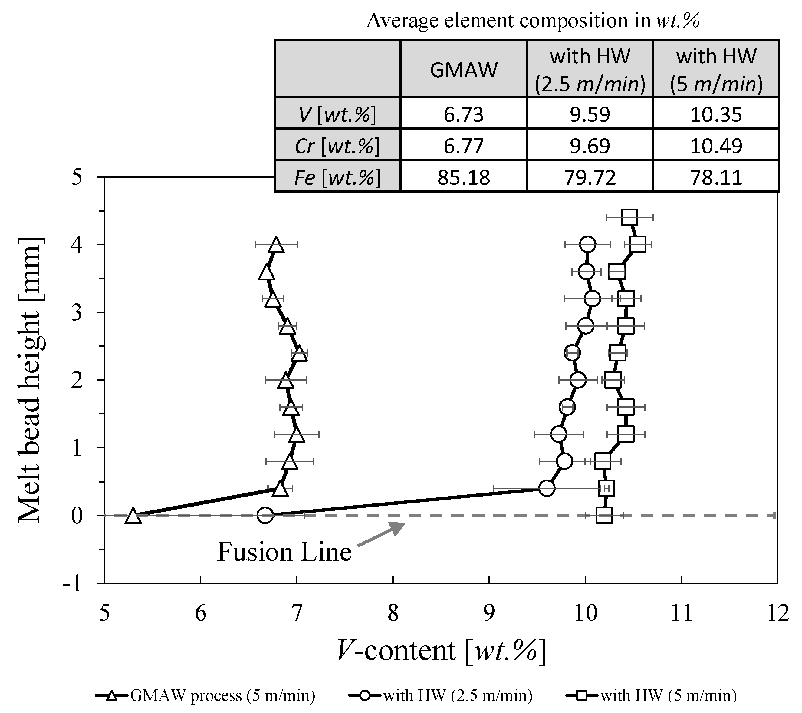
Figure 7.
Microstructural characteristics of the FeV12 hardfacing and comparison between (a) light microscopy and (b) backscatter electron microscopy.
Figure 7.
Microstructural characteristics of the FeV12 hardfacing and comparison between (a) light microscopy and (b) backscatter electron microscopy.

Figure 8.
Influence of an additional hot wire on the microstructural properties; primary vanadium carbides (VCs) (1), eutectic VCs (2), and eutectic Cr-rich carbides (3). (a) Microstructure of conventional GMAW (vGMAW = 5 m/min) with a primary VC-content of 5.9 A%, (b) by applying an additional hot wire (vHW = 2,5 m/min), the amount of primary VCs increased to 15.3 A%, (c) by applying an additional hot wire (vHW = 5 m/min), the amount of primary VCs increased to 15.7 A%.

Figure 9.
Agglomeration of primary VCs during hot wire assisted gas metal arc welding (HW-GMAW).
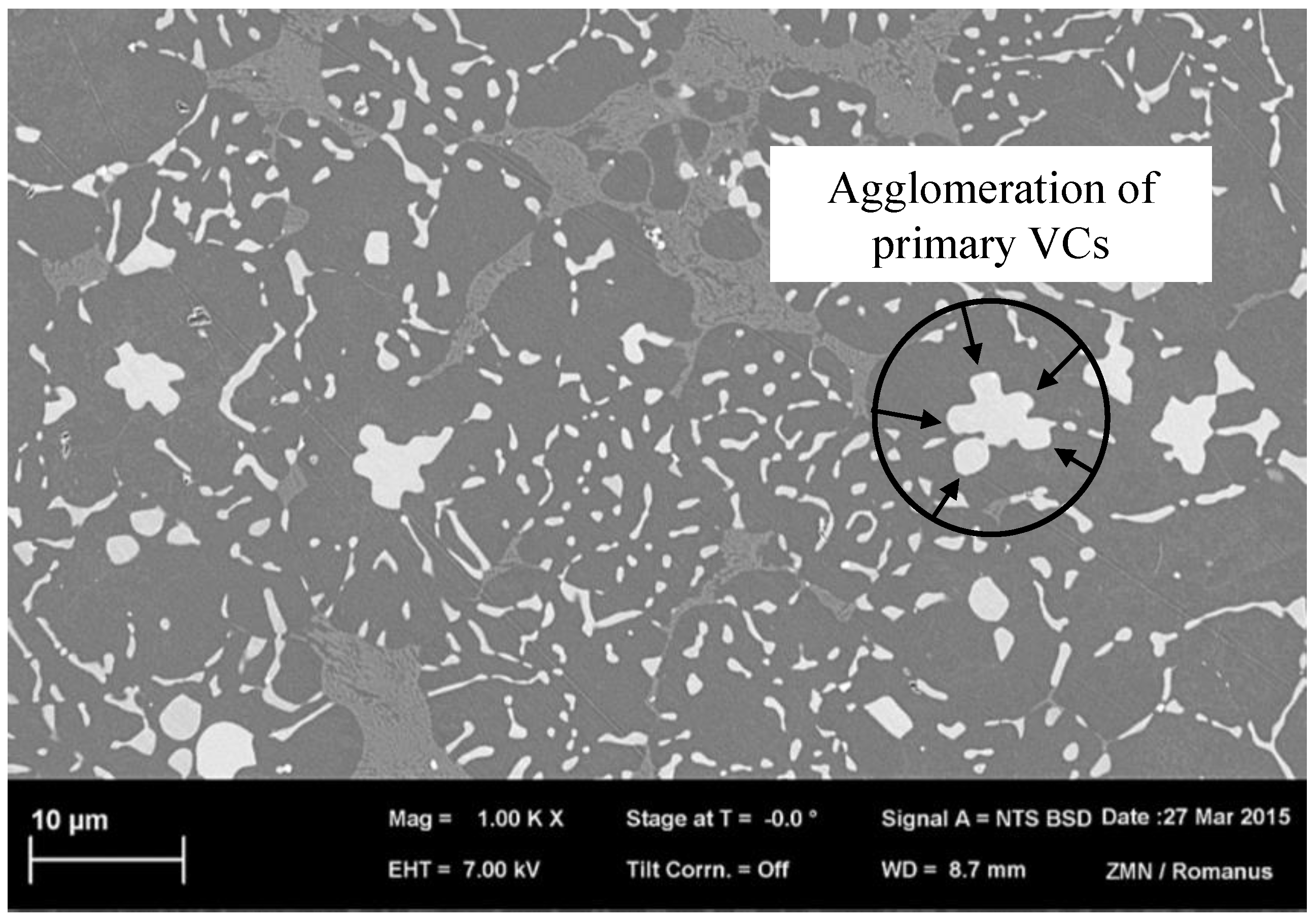
Figure 10.
Microstructure and characteristic of primary VCs (1) of (a) a single-layer HW-GMAW, vGMAW = 5 m/min, vHW = 5 m/min, vS = 300 mm/min; and (b) a three-layer GMAW overlay, vGMAW = 5 m/min, UGMAW = 29 V, vS = 300 mm/min.
Figure 10.
Microstructure and characteristic of primary VCs (1) of (a) a single-layer HW-GMAW, vGMAW = 5 m/min, vHW = 5 m/min, vS = 300 mm/min; and (b) a three-layer GMAW overlay, vGMAW = 5 m/min, UGMAW = 29 V, vS = 300 mm/min.
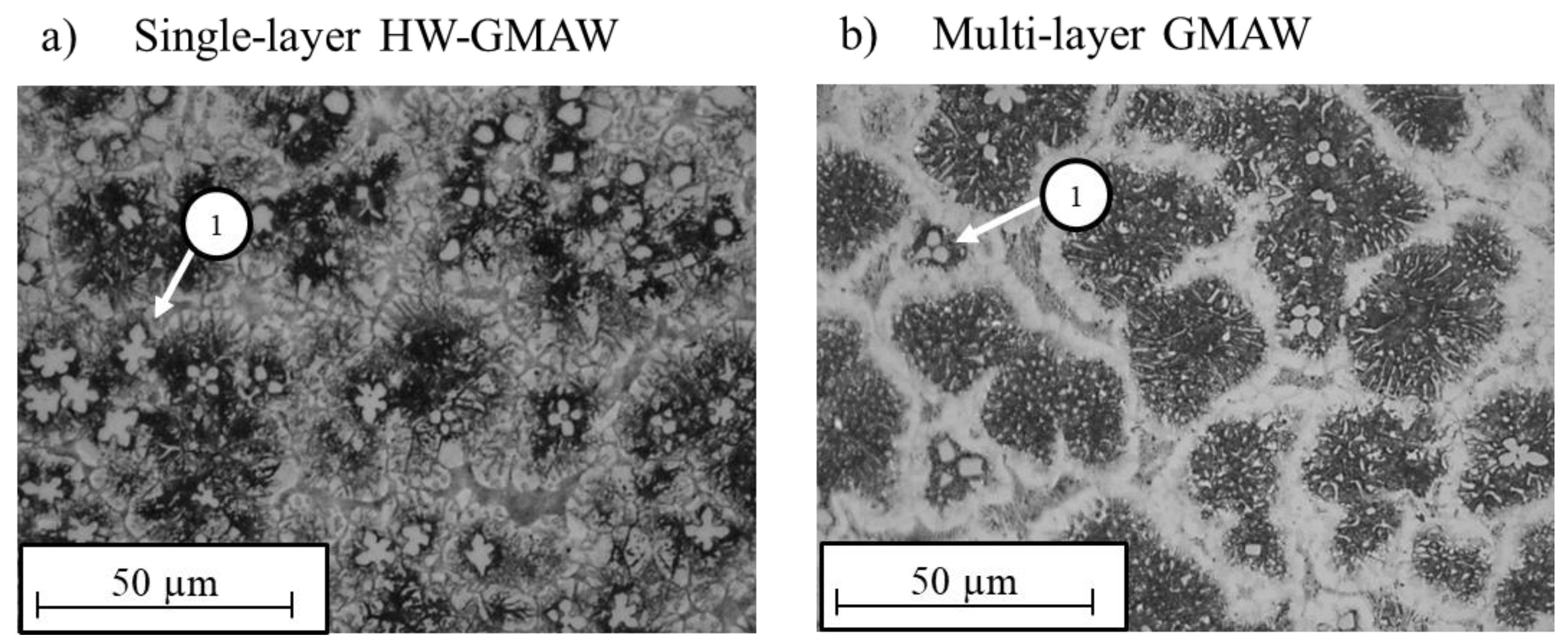
Figure 11.
Appearance of element residues on the melt bead surface due to hot wire application during GMAW. (a) Melt bead formation during GMAW (b) HW-GMAW reveals residues on the melt bead surface.
Figure 11.
Appearance of element residues on the melt bead surface due to hot wire application during GMAW. (a) Melt bead formation during GMAW (b) HW-GMAW reveals residues on the melt bead surface.

Table 1.
Chemical composition of the filler wire FeV12 (ø 1.2 mm).
| Elemental Composition (wt.%) | |||||||
|---|---|---|---|---|---|---|---|
| C | Si | Cr | Ni | Mo | V | Mn | Fe |
| 2.7 | 0.6 | 11.5 | 0.45 | 1.2 | 12.0 | 0.3 | Balance |
Table 2.
Electron dispersive X-ray analysis (EDX) measurements of the examined positions illustrated in Figure 7.
Table 2.
Electron dispersive X-ray analysis (EDX) measurements of the examined positions illustrated in Figure 7.
| Detected Element | Element Composition of the Examined Positions (wt.%) | |||
|---|---|---|---|---|
| Position 1 Primary Vanadium Carbides | Position 2 Eutectic Vanadium Carbides | Position 3 and 4 Iron-Rich Matrix (Martensite and Retained Austenite) | Position 5 Chromium-Rich Eutectic Carbides | |
| C K | 20.21 | 8.52 | 4.69 | 8.80 |
| O K | 0.00 | 0.00 | 0.00 | 0.00 |
| Si K | 0.49 | 0.69 | 0.85 | 0.49 |
| S K | 0.10 | 0.00 | 0.15 | 0.00 |
| V K | 61.91 | 8.32 | 4.20 | 6.39 |
| Cr K | 5.30 | 9.85 | 7.60 | 19.86 |
| Fe K | 11.99 | 69.85 | 78.76 | 60.04 |
| Ni K | 0.00 | 0.27 | 0.35 | 0.17 |
| Mo K | 0.00 | 2.50 | 3.40 | 4.25 |
© 2020 by the authors. Licensee MDPI, Basel, Switzerland. This article is an open access article distributed under the terms and conditions of the Creative Commons Attribution (CC BY) license (http://creativecommons.org/licenses/by/4.0/).
Share and Cite
MDPI and ACS Style
Günther, K.; Bergmann, J.P. Influencing Microstructure of Vanadium Carbide Reinforced FeCrVC Hardfacing during Gas Metal Arc Welding. Metals 2020, 10, 1345. https://doi.org/10.3390/met10101345
AMA Style
Günther K, Bergmann JP. Influencing Microstructure of Vanadium Carbide Reinforced FeCrVC Hardfacing during Gas Metal Arc Welding. Metals. 2020; 10(10):1345. https://doi.org/10.3390/met10101345
Chicago/Turabian StyleGünther, Karsten, and Jean Pierre Bergmann. 2020. "Influencing Microstructure of Vanadium Carbide Reinforced FeCrVC Hardfacing during Gas Metal Arc Welding" Metals 10, no. 10: 1345. https://doi.org/10.3390/met10101345
Note that from the first issue of 2016, this journal uses article numbers instead of page numbers. See further details here.