Article

Influence of Exposure to Environment on Degradation of a Friction Stir Welded Aluminum Alloy

1
National Key Laboratory of Science and Technology on UAV, Northwestern Polytechnical University, Xi’an 710072, China
2
School of Aeronautics, Northwestern Polytechnical University, Xi’an 710072, China
3
Innovation Group of Marine Engineering Materials and Corrosion Control, Southern Marine Science and Engineering Guangdong Laboratory, Zhuhai 519080, China
4
Department of Mechanical Engineering, The University of Akron, Akron, OH 44325, USA
*
Author to whom correspondence should be addressed.
Metals 2020, 10(11), 1437; https://doi.org/10.3390/met10111437
Submission received: 28 September 2020 / Revised: 18 October 2020 / Accepted: 26 October 2020 / Published: 29 October 2020
(This article belongs to the Special Issue Surface Engineering of Metals and Alloys)

Abstract

:
We carried out a comparative study on both the stress corrosion response and corrosion damage characteristics of aluminum alloy 2219, both the base material and a friction stir welding (FSW) counterpart upon exposure to exfoliation corrosion (EXCO) solution. The results reveal that the test specimen containing an FSW joint reveals better electrochemical corrosion resistance than that taken from the base metal. When test specimens upon exposure to EXCO solution are concurrently subjected to a tensile stress, since the mechanical properties of the FSW joint are lower than the base metal, a test specimen containing an FSW joint is more easily prone to the early initiation of fine microscopic cracks. This makes the test specimen containing the FSW joint to be less resistant to stress corrosion damage than that taken from the base metal for the various levels of applied stress and exposure time to EXCO solution. The average corrosion depth of the test specimen containing the FSW joint is less than that of the base metal, while the maximum corrosion depth of it is greater than that of the base metal. This reveals that test specimen containing the FSW joint is more susceptible to damage and degradation than test specimen taken from the base metal.

1. Introduction

Aluminum alloy 2219 is an Al-Cu-Mn alloy that is receptive to heat treatment. This alloy offers the characteristics of low density, high specific strength (σ/ρ), good heat resistance coupled with high sensitivity to stress corrosion. Friction stir welding (FSW) is a new material joining technology invented by The Welding Institute (TWI) in 1991. During FSW process, a rotating stirring pin is inserted between the workpieces to be welded and moves along the welding path. The stirring head shoulder and the stirring pin rub against the workpiece to be welded and generate a lot of heat. The workpiece is heated to below the melting point and in a plastic state under the action of heat, and the solid-phase connection of the material is realized under the action of stirring and clamping force [1]. The technique of FSW is essentially a solid-phase bonding technology. Compared one-on-one with the traditional fusion welding methods, the FSW joint of an aluminum alloy has a more homogeneous microstructure coupled with the presence of fewer defects [2,3]. During FSW, the chosen aluminum alloy is subjected to stirring caused by a stirring needle coupled with heat input. This favors the occurrence of plastic deformation at the fine microscopic level coupled with dynamic recrystallization and a resultant change to the microstructure. A change in microstructure often results in a change in mechanical properties of both the FSW joint and the adjacent material. The literature shows that in the FSW process, the metal material is stirred by the stirring pin, resulting in a large amount of heat input, plastic flow, and dynamic recrystallization to occur. Consequently, the microstructure of the formed welded joint changes compared to the base material, which leads to the performance of the material in the welded joint zone becoming different from the base material. Fratini studied the correlation between the flow of material and the microstructure of the weld nugget during friction stir welding of 7075 aluminum alloy and predicted the grain size of the weld joint zone [4]. Gan discovered the abnormal growth of grains in the weld zone and heat-affected zone of aluminum alloy 5083 and 6111 friction stir welding and described the relationship between process parameters, microstructure changes, and mechanical properties of the joint zone [5].
An FSW joint does result in three microscopic zones [6,7]. These are the following:
  • The nugget zone (NZ).
  • Thermo-mechanical affected zone (TMAZ).
  • Heat-affected zone (HAZ).
In the NZ, which is subjected to the action of stirring caused by the stirring needle coupled with high temperature, the end result is the formation and presence of fine equiaxed grains. The TMAZ is not directly stirred by the stirring needle. Consequently, it experiences a lower degree of plastic deformation at the “local” level coupled with lower thermal influence than the NZ. This often results in the formation and presence of elongated grains with the grain size being noticeably larger than that of the NZ. The HAZ is also subjected to a thermal cycle caused by the stirring action that causes the grains in this zone to grow and eventually coarsen. Due essentially to plastic damage caused by the crushing action of stirring and welding-related defects, such as looseness and holes, which are difficult to avoid in the weld zone, there does exist an overall weak joint whose strength is about 55 pct. to 80 pct. of the base metal. A noticeable change in both microstructure and resultant properties does make the damage due to stress corrosion experienced by the FSW joint to be noticeably different from that of the base metal.
The FSW region of an aluminum alloy is a complex zone that essentially has an uneven structure and resultant unpredictable mechanical performance. Different materials coupled with different welding process parameters will tend to make the microstructure at the region of the joint to be different. Furthermore, different environments in synergism with different loads will tend to promote varying degree of environment-induced interactions and/or degradation. Therefore, FSW joint of an aluminum alloy does exhibit complex characteristics when interacting with the environment and the resultant environment-induced degradation, which is referred to as corrosion. During service, the material chosen is often subjected to the conjoint influence of corrosive medium and static stress. Thus, there does exist the risk of inducing conditions that are favorable for the initiation of stress corrosion cracking. Over the years, few researchers have systematically conducted a sizeable amount of research on the corrosion characteristics of both aluminum alloys and their FSW counterparts. Some of these research scholars are of the belief that FSW tends to reduce the overall corrosion resistance of the joint. Wang used water-cooled friction stir welding to improve the microstructure of aluminum alloy 7055 and found the mechanical properties of the joint were improved, but the corrosion behavior of the alloy was affected [8]. Gharavi and Matori and co-workers studied the corrosion behavior of the FSW joint of aluminum alloy 6061-T6 [9,10]. They found the corrosion resistance of the NZ to decrease because of two reasons, and these are the following:
  • Since pitting corrosion occurred both at and along the edges of the intermetallic compounds present in the microstructure, an increase in both the presence and distribution of intermetallic compounds in the NZ contributes to a gradual increase in the corrosion galvanic couple.
  • A refinement in grain structure of the NZ results in an increase in corrosion sensitivity.
The experiments of Lumsden et al. also support the above findings and conclusion [11,12]. Through a series of corrosion experiments systematically conducted on FSW joints of aluminum alloy 7075-T7651, they found that, due to the depletion of copper in the precipitation free zone (PFZ) present both at and along the grain boundary regions, the pitting potential of the NZ decreased favoring the occurrence of selective grain boundary corrosion that only resulted in a gradual decrease in resistance to intergranular corrosion. The interface between the NZ and zone of incomplete recrystallization became the most sensitive zone for the occurrence of damage due to stress corrosion cracking. In this zone, it was easy for the fine microscopic cracks to propagate, eventually resulting in failure by intergranular fracture. This contributed to reducing the overall resistance of the test specimen containing the FSW joint to stress corrosion cracking. Chen studied and documented the microstructure, mechanical properties, and corrosion behavior of friction stir welded joints of aluminum alloy 5086 and aluminum alloy 6061 [13]. He observed noticeable differences in microstructure, mechanical properties and corrosion behavior of the different zones for the two aluminum alloys. He also found the corrosion resistance of the FSW joint of the chosen aluminum alloy to reveal noticeable improvement. Esmaily and co-workers studied the corrosion performance of aluminum alloy 6005-T6 having a double shoulder FSW joint using the atmospheric corrosion experiment [14]. They found and recorded the overall corrosion performance of the joint zone to be superior to that of the base metal. Venugopal studied the pitting corrosion resistance of FSW joint of aluminum alloy 7075 in a 5 percent sodium chloride (NaCl) solution [15]. He found the corrosion resistance of the NZ to be better than both the TMAZ and the base metal. Wadeson and co-workers studied and documented the overall corrosion resistance of aluminum alloy 7108-T79 containing an FSW joint [16]. They found the edge of the TMAZ to be receptive to environment-induced degradation, or corrosion, which did gradually extend to the HAZ due essentially to the uneven precipitation of the strengthening precipitates (both η and η’) in the TMAZ. Paglia and co-workers found from their experiments that a noticeable difference in both microstructure and microchemistry of an FSW high-strength aluminum alloy contributes to deteriorating the overall environment-induced degradation, or corrosion, while coarsening of the strengthening precipitates present both at and along the grain boundaries promoted the occurrence of intergranular corrosion at the region of the FSW joint [17,18]. Corrosion occurred both at the NZ and the HAZ. The HAZ was found to be least resistant to degradation by corrosion. This can essentially be attributed to the width of the copper-depleted PFZ that is present both at and along the grain boundary regions. Lumsden and co-workers pointed out that for the FSW joint of aluminum alloy 7075-T651, the NZ had a lowest pitting potential, and pitting potential of the HAZ was noticeably lower than that of the base metal [11]. Emilie and co-workers found and documented the FSW joint of aluminum alloy 2024-T3 to experience most severe intergranular corrosion at the HAZ [19]. Both pitting corrosion and intergranular corrosion occurred in the base metal and the TMAZ, and pitting corrosion in NZ. Litwhiski and co-workers in their independent study pointed out that the TMAZ was easily susceptible to corrosion for the FSW aluminum alloy 2195 [20]. Padgett studied both the cracking and “local” corrosion behavior of FSW joint of aluminum alloy 2099 under conditions of environmental impact [21]. They observed the edge of the HAZ, on the retreating side of a joint, to be most sensitive to stress corrosion cracking (SCC). However, the experiment of Chen revealed the retreating side to have much better corrosion resistance than the other zones of the aluminum alloy chosen and studied [13]. Paglia and co-workers found the microstructure of each zone of an FSW joint of aluminum alloy 2219-T87 to be different [18]. However, overall SCC behavior was found to be the same. The test specimen when deformed in tension failed at the junction of the NZ and the TMAZ. Astarita and co-workers studied the stress corrosion cracking behavior of the following FSW aluminum alloys: (i) 2024-T3, (ii) 2139-T3, (iii) 2198-T3, and (iv) 6056-T4 [22]. These researchers found the FSW joints of the chosen and studied aluminum alloys to have noticeably different stress corrosion characteristics. For the 2XXXseries aluminum alloy, the FSW joint exhibited anodic characteristics relative to the base metal, while for the 6XXX-series aluminum alloy, the FSW joint exhibits cathodic characteristics relative to the base metal.
A careful review of the published literature reveals the different studies conducted on different aluminum alloys resulted in observable differences in the conclusions. The reason for this being that corrosion of an aluminum alloy is a complex process, which is affected by the conjoint and mutually interactive influences of several factors. For example, composition of the chosen aluminum alloy is different, or the process parameters chosen for FSW are marginally different. This results in observable differences in the microstructure. Further, while in service different loads on an aluminum alloy will tend to promote different corrosion processes occurring at the fine microscopic level often culminating in different degree and/or severity of damage. Among the variables, the nature of corrosion medium chosen and applied stress level are two key factors that exert an influence on both the occurrence and severity of damage due to stress corrosion at the FSW joint. Therefore, in this study, exfoliation corrosion (EXCO) solution was chosen as the corrosive medium to study the stress corrosion characteristics of aluminum alloy 2219 when under the influence of a tensile stress. The objective was to help both in establishing and understanding the influence of intrinsic microstructural changes occurring at the joint on overall damage caused to the chosen aluminum alloy due to stress corrosion.

2. Materials and Methods

The test material chosen was aluminum alloy 2219. The as-provided plate stock had a thickness of 2.5 mm. The chemical composition of the as-provided alloy is as shown in Table 1. The physical and mechanical properties of the as-provided alloy are summarized in Table 2. Two of the as-provided aluminum alloy plates were welded using the technique of FSW. The test specimens were precision cut from the welded plates using the technique of wire cutting. Two kinds of test specimens chosen for this study were prepared from both the as-provided aluminum alloy plate and the FSW alloy plate. The test specimens taken from the base metal, i.e., as provided aluminum alloy 2219, were cut along the edges of the as-provided plate. The test specimen taken from the FSW aluminum alloy plate was cut along the weld direction at the region of the welded joint. Both the FSW joint specimen and test specimen taken from the base metal, i.e., as-provided aluminum alloy, had the same shape and size. This is shown in Figure 1. Tensile strength of the FSW joint specimen of aluminum alloy 2219 was 295 MPa, which is 62% of the tensile strength of test specimen of the base metal, i.e., as-provided aluminum alloy.
Both stress level and duration of exposure to an aqueous solution were chosen as the control variables. Consequently an experimental scheme was designed to carry out the accelerated corrosion tests on both FSW test specimens of aluminum alloy 2219 and the unwelded alloy, i.e., the base metal (aluminum alloy 2219). The experiments were carried out at room temperature (24 °C) and laboratory air environment (relative humidity of 55%). The test specimens were subject to three different stress levels, i.e., (i) 0 MPa, (ii) 79 MPa, and (iii) 118.5 MPa, corresponding to 0%, 20%, and 30% of the yield strength of the chosen aluminum alloy. At each stress level, the duration of exposure of test specimens of the aluminum alloy to the environment was (i) 8 h, (ii) 16 h, (iii) 24 h, and (iv) 48 h. By observing the morphology and severity of environment-induced degradation and concurrently measuring the depth of corrosion-induced damage experienced by test specimens of the chosen aluminum alloy, the overall severity of damage experienced by the test specimens taken from the base metal and the FSW joint are compared. In an attempt to avoid deviation of the test results arising from a dispersion of material properties, the experiment was designed to be conducted in triplicate, i.e., testing three specimens for each condition.
The environment chosen for purpose of this study was an EXCO solution prepared very much in conformance with specifications and procedures detailed in Standard ASTM G34-01 [23]. Composition of the solution is provided in Table 3 and had a starting pH value of 0.4.
The key equipment required for the experiment was the following:
  • A loading device for the stress corrosion test was used to apply a constant tensile stress on the test specimen while being exposed to the environment during loading;
  • A continuous zoom video microscope (Model: UNION DZ3; Union.Co., Chuo-ku, Kobe, Japan) was used to observe the morphology, nature, extent and severity of environment-induced damage, or corrosion experienced by the test specimens taken from both the base metal and the FSW joint.
  • A low magnification scanner (Model: HP 8200, Hewlett-Packard, Palo Alto, CA, USA) used to establish the macroscopic corrosion morphology both at and surrounding the zone of corrosion.
  • A laser displacement sensor (Model: Keyence LK-G30, Keyence (China) Co. Ltd., Shanghai, China) to measure the depth of pits on the surface of test specimens exposed to the aggressive aqueous solution (i.e., EXCO solution) while concurrently obtaining distribution data specific to depth of the pit. The measurement accuracy of the instrument can reach 0.02 μm.
For test specimens taken from the base metal, i.e., as provided aluminum alloy plate, and test specimens containing the FSW joint, the following steps were repeated. The chosen test specimens were polished to a near mirror-like surface finish with progressively finer grades of silicon carbide (SiC) impregnated emery paper (i.e., 400-grit, 600-grit, 800-grit, 1000-grit, 1200-grit, 1500-grit, 2000-grit, 2500-grit, 3000-grit, and 5000-grit). The as-polished test specimens were cleaned using anhydrous ethanol and subsequently dried in ambient air. The middle part of the test specimen, measuring 20 mm by 6 mm, was reserved for the corrosion test. Other portions of the chosen test specimen were coated and sealed with paraffin in a hot melting state. This is shown in Figure 2. The corrosion zone of the chosen test specimen was then exposed to the chosen aqueous environment, i.e., EXCO solution. According to ASTM standard, the quantity of solution taken should be 70 ml. A specified tensile stress was applied at both ends of the chosen test specimen. When the specified duration of exposure to the aggressive aqueous environment was reached, the test specimen was unloaded and removed. Concentrated nitric acid (65%) was used to wipe the “exposed” area of the test specimen with the prime intent of removing the presence of corrosion products. An ultrasonic vibration cleaner was then used to clean the test specimen surface using anhydrous ethanol with the prime purpose of removing any residual corrosion products. The test specimen was then dried using high-velocity/speed air from a hair blower. The laser depth measuring instrument was used to both measure and record any change in depth of the exposed surface along the longitudinal symmetry center line of the corroded test specimen of aluminum alloy 2219, and about 600 surface depth changes can be obtained per millimeter. Approximately 12,000 data points can be obtained for each measurement line, which can quantitatively reflect the damage of the specimen. For a joint specimen, the data quantitatively represent the damage in the NZ. A damage model, due to corrosion of the test specimen surface, can be established using the data collected on depth of the test specimen surface. This provides a measure of the corrosion damage experienced by the test specimen for different levels of applied stress and duration of exposure to the aqueous environment (i.e., EXCO solution). A scanner was used to record the macroscopic morphology of corrosion on the surface of the chosen test specimen. The microscopic morphology of the corroded region of the test specimen was observed in a high magnification microscope.
Since there are two types of specimens ((i) specimen taken from FSW alloy plate and (ii) specimen taken from the as-provided aluminum alloy plate), three levels of applied stress, and four durations of exposure to the environment, a total of 24 tests was carried out. Each test was repeated three times for the purpose of ensuring consistency in the test results.

3. Results and Discussion

3.1. Analysis of Morphology of Electrochemical Corrosion

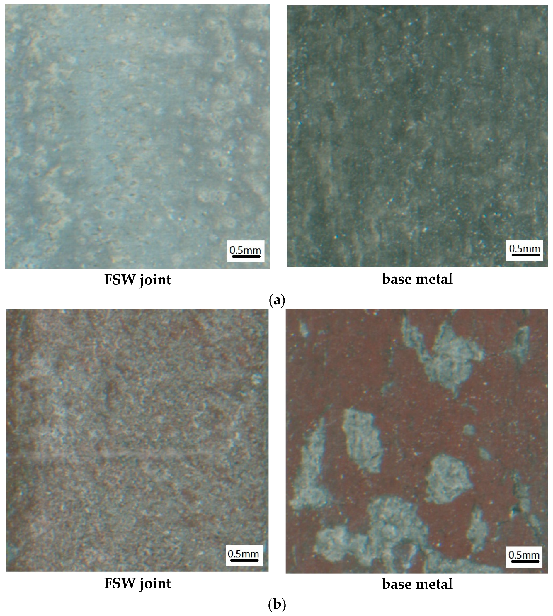
3.1.1. Morphology at the Macroscopic Level

When the value of applied stress is 0 MPa, the test specimen experiences pure electrochemical corrosion. When the test specimen of aluminum alloy 2219 was exposed to the aqueous environment, i.e., EXCO solution, pitting-induced damage was favored to occur. With an increase in the duration of exposure to the aqueous environment, corrosion of the surface of the test specimen gradually increased and tended to become uniform, appearing to the naked eye as spalling corrosion. Results of the tests reveal that corrosion of the test specimen containing the FSW joint and test specimen of the base metal gradually increases with an increase in the duration of exposure to the aqueous environment. For the same duration of exposure to the aqueous environment, i.e., EXCO solution, the corrosion experienced by test specimen of aluminum alloy 2219 containing the FSW joint was noticeably less than that of the test specimen taken from the base metal, i.e., alloy 2219. The macroscopic corrosion morphology of the test specimen containing the FSW joint and test specimen of the base metal, under identical conditions, is shown in Figure 3. It is observed from (a) that when duration of exposure to the aqueous environment is 8 h, small pits were observed on the surface of the test specimen containing the FSW joint providing an indication of the occurrence of pitting. The pits were independent of each other but also easily distinguishable. The surface of the test specimen of the base metal revealed a dense distribution of pits with the edges of a pit being difficult to distinguish. When duration of exposure to the aqueous environment (EXCO solution) was extended to 24 h, it can be observed from Figure 3b that pitting corrosion on the surface of the test specimen containing the FSW joint was visibly increased, while the extent and severity of corrosion of the test specimen taken from the base metal was noticeably observable, i.e., several areas of the test specimen revealed an evidence of flakes that had peeled off. Therefore, a test specimen containing the FSW joint revealed much better corrosion resistance than test specimen taken from the base metal.

3.1.2. Microscopic Morphology of Pure Electrochemical Corrosion

The friction stir welding process makes it possible for the weld zone to develop a precipitation free zone at and along the grain boundaries. Therefore, when the test specimen of aluminum alloy 2219 containing an FSW joint is exposed to the aqueous EXCO solution, the formation and presence of pits both at and along the grain boundary region is favored to occur. The morphology of corrosion, at the fine microscopic level, for the test specimen containing the FSW joint following 8 h of exposure to the aqueous environment, i.e., EXCO solution, is shown in Figure 4. It can be seen that there are several pits in the exposed zone, all of which are initiated at the grain boundary. A change in morphology of corrosion for the test specimens containing the FSW joint and exposed to the EXCO solution for different duration of times is shown in Figure 5. With an increase in duration of exposure to the aqueous EXCO solution results in the following:
  • The magnitude and severity of corrosion experienced by the test specimens increases.
  • The density of pits increases with the smaller pits gradually growing and developing to become larger pits.
  • The grain boundaries tend to gradually dissolve indicating the occurrence of intergranular corrosion.
When duration of exposure to the EXCO solution is 48 h, the overall integrity of the test specimen surface is severely damaged, which has a deleterious influence on overall performance of the test specimen containing the FSW joint.

3.2. Analysis of Morphology of Stress Corrosion

3.2.1. Morphology of Stress Corrosion at the Macroscopic Level

When the chosen test specimen is exposed to the EXCO solution and concurrently subjected to a tensile stress, stress corrosion is favored to occur for both the specimen containing the FSW joint and the specimen taken from the base metal. Stress corrosion is more dangerous than pure electrochemical corrosion, since the conjoint influence of stress and corrosion medium favor the initiation of pits, whose gradual growth and eventual coalescence results in the initiation of fine microscopic cracks. Furthermore, due to the lower tensile strength of the test specimen containing the FSW joint, it is easier to initiate fine microscopic cracks at the grain boundary region and to grow these into the grain eventually culminating in failure by fracture. This suggests that the formation, presence, and growth of fine microscopic cracks is far more dangerous culminating in failure of the component. However, it was difficult to observe the development and presence of pits and their ensuing growth through the depth, or thickness, of the test specimen and the concomitant initiation of fine microscopic cracks only by observing the macro corrosion morphology of the specimen. Therefore, from a macroscopic viewpoint corrosion experienced by test specimen containing the FSW joint was noticeably less than that of the base metal. A comparison of the macroscopic morphology of corrosion of the test specimen containing the FSW joint and test specimen of the base metal at an applied stress value of 79 MPa, and duration of exposure to the EXCO solution for 8 h and 24 h is shown in Figure 6. It is easily observed that the degree of environment-induced damage experienced by the test specimen of the base metal (i.e., aluminum alloy 2219) was more severe than the test specimen containing the FSW joint for a given duration of exposure to the aqueous environment, i.e., EXCO solution. Therefore, from macroscopic observation of the environment-induced damage, it is clear that specimens containing the FSW joint revealed better resistance to damage resulting from exposure to the aqueous environment.

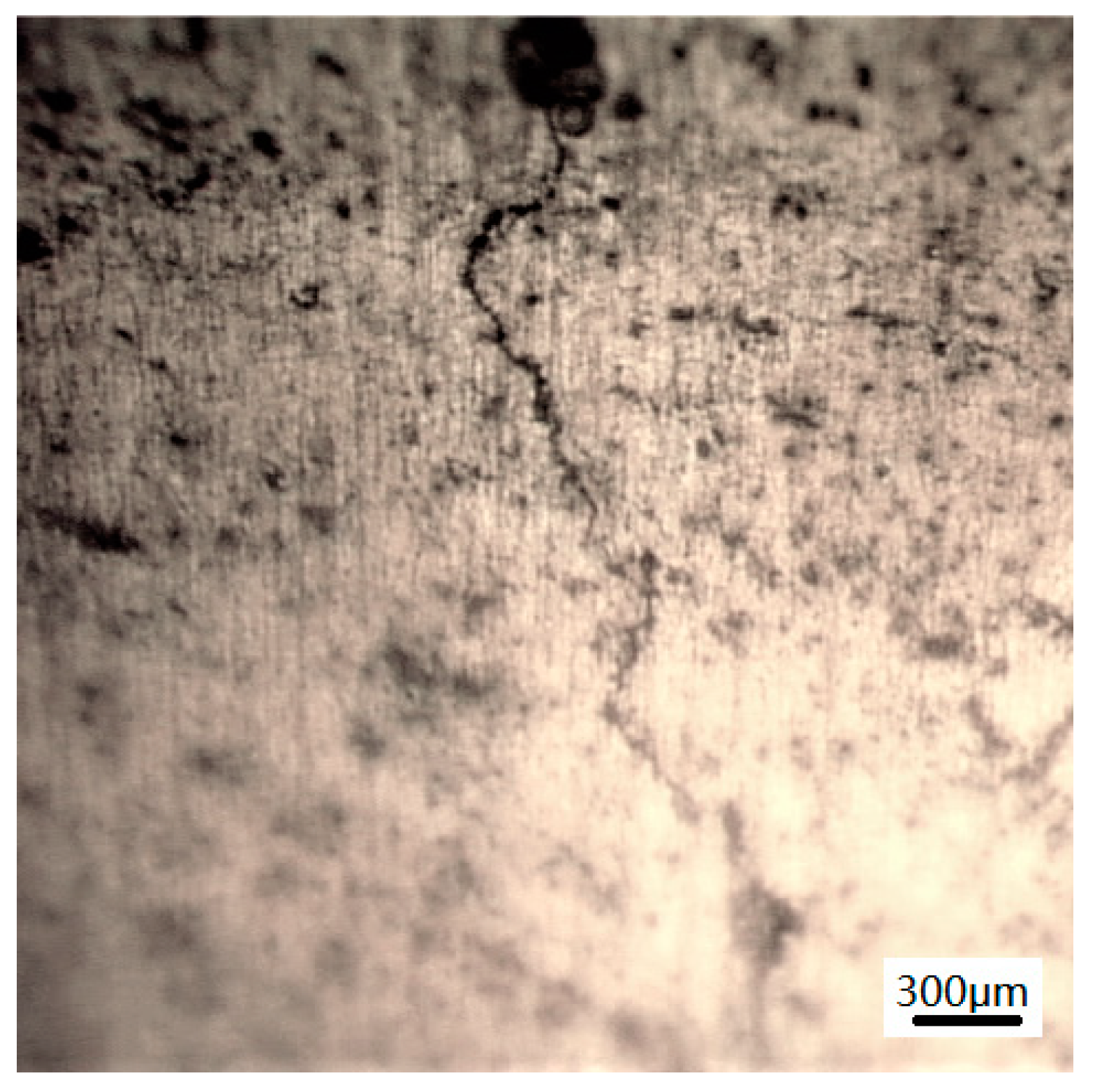
3.2.2. Morphology of Stress Corrosion at the Microscopic Level

For a test specimen, which experiences environment-induced damage, such as corrosion, the presence of pits and fine microscopic cracks can also be observed at the same time. Some of the fine microscopic cracks originate from the pits and often tend to extend along the grain boundaries. A few of these fine microscopic cracks will tend to grow through the grain. The conjoint influence of applied stress and exposure to an aggressive environment, such as EXCO solution, will promote the development of pits through the thickness, while concurrently promoting the initiation, coalescence, and propagation of cracks. Due to a gradual loss of the second-phase particles present both at and along the grain boundaries of the FSW joint, the intergranular region is relatively weak causing mechanical properties of the joint to progressively degrade. Therefore, for the same magnitude of applied stress and exposure to an aggressive aqueous environment, the test specimen with a friction stir welded joint is noticeably more susceptible to stress corrosion cracking than test specimen of the base metal.
A comparison of the microscopic morphology of the test specimen containing an FSW joint with the test specimen of the as-provided aluminum alloy upon exposure to the EXCO solution for full 16 h under the action of a tensile stress of 79 MPa is shown in Figure 7. It is observed that degradation of the test specimen surface was evident for both specimens. However, the extent and severity of surface damage experienced by test specimen containing the FSW joint is noticeably smaller and reveals an overall better resistance to damage induced by the aqueous environment (i.e., EXCO solution) when compared one-on-one with test specimen taken from the base metal, i.e., aluminum alloy 2219. Further, fine microscopic cracks arising from environment-induced damage were found on the test specimen containing the FSW, as shown in Figure 8, but no fine microscopic cracks were observed on the surface of test specimen taken from the base metal. The most appealing rationale for this observation is that upon exposure to the same aqueous medium (EXCO solution) and same level of applied stress, the fine microscopic cracks initiated earlier in the test specimen containing the FSW joint due to its lower tensile strength than the test specimen taken from the base metal.
When the stress value increases to 118.5 MPa, fine microscopic cracks were observed on the surface of test specimen of the base metal following 16 h of exposure to the EXCO solution, as shown in Figure 9a. For the test specimen containing the FSW joint under identical conditions, more serious stress-corrosion-induced microscopic cracking was observed, as shown in Figure 9b; the cracks developed were significantly wider than the cracks formed and present on the surface of test specimen of the base metal. Under identical conditions, multiple cracks were found to be distributed on the surface of the test specimen containing the FSW joint. Therefore, under identical conditions, the environment-induced damage experienced by the specimen containing the FSW joint was more severe than the specimen of the base metal, i.e., aluminum alloy 2219. The most appealing reason for this is that tensile strength of the test specimen containing the FSW joint is lower than the tensile strength of test specimen taken from the base metal, and the intergranular corrosion experienced by the test specimens upon exposure to the EXCO solution causes the grain boundary to gradually weaken and concurrently reducing the binding force between the grains, so when the test specimen is subjected to a tensile stress, it becomes noticeably easier to initiate fine microscopic cracks along the grain boundary region . The cracks in the test specimens containing the FSW joint tend to progress along the weakened grain boundaries resulting in conditions conducive for premature failure by intergranular fracture. This is shown in Figure 10. Consequently, overall resistance of test specimen of aluminum alloy 2219 containing the FSW joint upon exposure to the EXCO solution is lower than that of the base metal.

3.3. Analysis of Damage Due to Corrosion

3.3.1. Model for Corrosion-Induced Damage

The polished specimen had a flat surface prior to the initiation of environment-induced damage, i.e., corrosion. Subsequent to the highly localized damage induced by the environment by way of corrosion, both pits and cracks were observed on the surface of the test specimen. The gradual loss of material from the surface was used to express damage experienced by the specimen intuitively. By using a laser displacement sensor, the data specific to change in depth of the test specimen surface were obtained. If the original height of the test specimen surface is taken to be zero, then surface height of the test specimen following exposure to the aqueous environment (i.e., EXCO solution) should be either less than or equal to 0 due to the damage. The height value at each point on the test specimen surface does provide a measure of both the extent and severity of environment-induced damage at that point. Therefore, the damage resulting as a direct consequence of exposure of the test specimen to the aqueous environment can be established by the change in surface depth caused by exposure to the environment and the resultant damage due to corrosion. The laser measurement data come from the longitudinal symmetry centerline of the specimen. For the joint specimen, this is the location of the NZ. The average distance between the measurement points is 5 μm, and the line connecting these points indicates the change in the corrosion depth on the measured surface. The corrosion depth curves for the test specimen containing the FSW joint for different duration of exposure to the chosen environment, i.e., EXCO solution, safely reflects the amount of environment-induced damage for the test specimen containing the FSW joint. The change curve of stress corrosion depth taken on a symmetrical section of the test specimen containing the FSW joint, along the direction of applied stress, following exposure to the EXCO solution for 8 h, 16 h, 24 h, and 48 h under the influence of an applied stress of 118.5 MPa, is shown in Figure 11. Since measurement of the depth was made along the longitudinal symmetry plane, the curves also provide information related to the damaged section of the nugget zone. It can be seen from this figure that with increased duration of exposure to the chosen aqueous environment, i.e., EXCO solution, the amount of damage increases.

3.3.2. An Analysis of Damage Due to Electrochemical Corrosion

The fitting curve depicting the average depth of corrosion for the two chosen specimens with duration of exposure to the aqueous environment (EXCO solution) is shown in Figure 12. The fitting curve depicting maximum depth of corrosion experienced by the two types of chosen test specimens with duration of exposure to the aqueous environment (EXCO solution) under conditions that promote pure electrochemical corrosion is shown in Figure 13. To avoid the influence of random factors, the data provided here are the average of three replicates. In an attempt to compare the risk of damage, the ratio (α) of maximum depth to the average depth is chosen for the purpose of comparison. A change in the ratio of α (maximum depth/average depth) for the two types of specimens over duration of expourse is shown in Figure 14. Here each "maximum corrosion depth" represents the average value of the maximum corrosion depth of three parallel specimens, and each “average corrosion depth” is the average value of the average corrosion depth of the three parallel specimens. α is the ratio of the mean of the maximum depth to the mean of the average depth. It is observed that the value of α for the two chosen specimens, i.e., (i) test specimen containing the FSW joint and (ii) test specimen of the base metal, i.e., aluminum alloy 2219, was 1.25. This helps us to conclude that the extent of damage experienced by the specimens is roughly the same. For the four chosen duration of exposure to the aqueous environment, i.e., EXCO solution, the average depth of corrosion and maximum depth of corrosion for the test containing the FSW joint is noticeably less than the corresponding values for the base metal, i.e., AA2219. This leads to the conclusion that when pure electrochemical corrosion occurs upon exposure to the EXCO solution, the environment-induced damage, i.e., corrosion, experienced by test specimen of aluminum alloy 2219 containing an FSW joint, is less than the damage experienced by the base metal, i.e., aluminum alloy 2219. This suggests that overall corrosion resistance of test specimen containing the FSW joint is noticeably improved when compared one-on-one with the base metal.
α = [ h m a x h a v e ] ,

3.3.3. A Comparative Analysis of Damage Due to Stress Corrosion

When the test specimen is subjected to the conjoint influence of stress and exposure to a corrosive medium, i.e., EXCO solution, the occurrence of SCC is favored. The conjoint and mutually interactive influences of both mechanical effect (applied stress) and chemical effect (i.e., exposure to the aqueous environment (EXCO solution) causes the material to be severely damaged with resultant damage to the components. Variation of the average corrosion depth for the test specimen of aluminum alloy 2219 containing the FSW joint and test specimen of the as-provided aluminum alloy 2219, i.e., the base metal, with duration of exposure to the environment, is shown in Figure 15. Variation of maximum corrosion depth for the test specimen of alloy 2219 containing the FSW joint and test specimen of the base metal specimen with duration of exposure at an applied stress of 79 MPa is shown in Figure 16. The average depth of corrosion experienced by the test specimen of aluminum alloy 2219 containing the FSW joint is noticeably smaller than for test specimen of the base metal, i.e., aluminum alloy 2219. The variation of ratio of maximum corrosion depth to the average corrosion depth (α) for test specimens of aluminum alloy 2219 containing the FSW joint and test specimens of the base metal (i.e., aluminum alloy 2219), under an applied stress of 79 MPa, is shown in Figure 17. It is seen that the ratio (α) for the test specimens containing the FSW joint is noticeably greater than that for test specimen taken from the base metal, for all of the four different durations of exposure to the aqueous environment (EXCO solution). The reason for this is that when a test specimen containing the FSW joint specimen is under stress, the pits initiated both at and along the grain boundary regions are more likely to develop and grow through the thickness. Consequently, the damage experienced by test specimens containing the FSW joint is observably more serious than the damage experienced by test specimens of the as-provided aluminum alloy 2219. Furthermore, the ratio [α] for the two chosen test specimens increases with an increase in duration of exposure to the chosen aqueous environment, i.e., EXCO solution. The increase is noticeably rapid for the specimen containing the FSW joint, while it is relatively slow for the test specimen prepared from the base metal, i.e., aluminum alloy 2219. This clearly indicates that the extent and severity of damage experienced by the specimen containing an FSW joint is noticeably more.

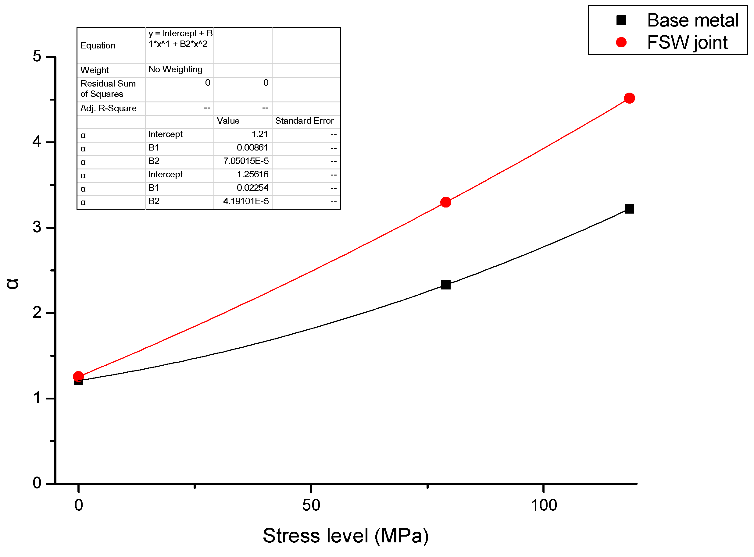
3.3.4. Relationship between Extent of Damage and Applied Stress

Stress is one of the basic factors that exerts an influence on both the initiation and progression, i.e., growth, of damage due to stress corrosion. The results of this study clearly indicate the existence of a relationship between the level of applied stress and the damage induced by exposure to the aqueous environment, i.e., EXCO solution, by way of corrosion. For an exposure time to the aqueous environment of 48 h, the variation of average corrosion depth with applied stress for the two chosen test specimens (i.e., (i) test specimen containing the FSW joint and (ii) test specimen of the base metal, i.e., aluminum alloy 2219) is shown in Figure 18. It is seen that the average corrosion depth for both specimens increases with an increase in the level of applied stress (σ), thereby indicating the depth of corrosion-induced damage to have a positive correlation with the magnitude of applied stress. At the three chosen applied stress (σ) levels of (i) 0 MPa, (ii) 79 MPa, and (iii) 118.5 MPa, the average depth of environment-induced damage, i.e., corrosion, experienced by the base metal is greater than that for the test specimen containing the FSW joint. This clearly indicates that overall corrosion resistance of the test specimen containing the joint reveals an improvement. Comparing the maximum depth of corrosion-induced damage for the two kinds of test specimens, i.e., test specimen containing the FSW joint and test specimen of the base metal, it is seen that at a value of applied stress of 0 MPa, i.e., pure electrochemical corrosion, the maximum corrosion depth experienced by specimen of the base metal is greater than that for test specimen containing the FSW joint. However, at applied stress levels of 79 MPa and 118.5 MPa, the maximum depth of corrosion for test specimens containing the FSW joint is greater than that of the base metal, as shown in Figure 19. The most appealing reason for this is that, although the FSW process improves the overall resistance to both corrosion and corrosion-induced damage of the specimen subject to pure electrochemical corrosion, the overall resistance to stress corrosion of the test specimen containing the FSW joint decreases due to an observable decrease in mechanical properties. This is shown in Figure 20. For pure electrochemical corrosion, the α values for the two chosen test specimens are the same, while for the case of stress corrosion, the α values for the two types of specimens chosen reveal an increase, with α values for the specimen containing the FSW joint increasing noticeably faster, providing evidence for the overall detrimental influence of the welded joint to stress corrosion.

4. Conclusions

The following are the key conclusions resulting from this exhaustive study.
  • When pure electrochemical corrosion occurs, the average corrosion depth and maximum corrosion depth of test specimen containing the joint are less than that of the test specimen of the base metal for four different durations of exposure to the aqueous environment. This suggests that the overall corrosion resistance of test specimens containing an FSW joint is better than that of the base metal.
  • When stress corrosion occurs, due to reduced mechanical properties of the test specimen containing the FSW joint, the stress corrosion resistance is inferior to that of the base metal, i.e., aluminum alloy 2219, and fine microscopic cracks are favored to occur.
  • When stress corrosion occurs, the average corrosion depth of test specimen of the alloy containing an FSW joint is less than that of the base metal. The maximum depth of corrosion is greater than that of the base metal. This indicates that the test specimen containing the FSW joint is more susceptible to damage and degradation than the base metal upon exposure to the same aqueous environment.
  • When stress corrosion occurs, the ratio of maximum depth to average depth (denoted as α) increases with an increase in applied stress and duration of exposure to the aqueous environment (EXCO solution).
  • The ratio (α) for test specimens containing the FSW joint is significantly higher than that for specimens of the base metal. Further, the observed increase in α with applied stress is faster for the test specimens containing an FSW joint than for test specimens of the base metal.

Author Contributions

Methodology, S.L.; validation, S.L. and X.G.; formal analysis, S.L.; investigation, Z.L.; data curation, Z.L.; writing—original draft preparation, S.L. and Z.L.; writing—review and editing, T.S.S.; funding acquisition, S.L. All authors have read and agreed to the published version of the manuscript.

Funding

This research was funded by Aeronautical Science Foundation of China, grant number 41402020401.

Acknowledgments

Shengli Lv are grateful for the support of this research under the Aeronautical Science Foundation of China and program 41402020401.

Conflicts of Interest

The authors declare no conflict of interest.

References

  1. Threadgill, P.L.; Leonard, A.J.; Shercliff, H.R.; Withers, P.J. Friction stir welding of aluminium alloys. Int. Mater. Rev. 2009, 54, 49–93. [Google Scholar] [CrossRef]
  2. Surekha, K.; Murty, B.S.; Prasad, R.K. Comparison of corrosion behaviour of friction stir processed and laser melted AA 2219 aluminium alloy. Mater. Des. 2011, 32, 4502–4508. [Google Scholar] [CrossRef]
  3. Williston, D.H. Comparison of joining processes for Haynes 230 nickel based super alloy. Ph.D. Thesis, Mississippi State University, Starkville, MI, USA, 2013. [Google Scholar]
  4. Fratini, L.; Buffa, G.; Palmeri, D. Material flow in FSW of AA7075-T6 butt joints: Continuous dynamic recrystallization phenomena. J. Eng. Mater. Technol. 2006, 128, 2857–2863. [Google Scholar] [CrossRef]
  5. Gan, W.; Okamoto, K.; Hirano, S.; Chung, K.; Kim, C.; Wagoner, R.H. Properties of friction-stir welded aluminum alloys 6111 and 5083. J. Eng. Mater. Technol. 2008, 130, 389–392. [Google Scholar] [CrossRef]
  6. Nandan, R.; Debroy, T.; Bhadeshia, H.K.D.H. Recent Advances in Friction-Stir Welding-Process, Weldment Structure and Properties. Prog. Mater. Sci. 2008, 53, 980–1023. [Google Scholar] [CrossRef] [Green Version]
  7. Sullivan, A.; Robson, J. Microstructural Properties of Friction Stir Welded and Post-Weld Heat-Treated 7449 Aluminum Alloy Thick Plate. Mater. Sci. Eng. A 2008, 478, 351–360. [Google Scholar] [CrossRef]
  8. Wang, Q. Corrosion behavior of spray formed 7055 aluminum alloy joint welded by underwater friction stir welding. Mater. Des. 2015, 68, 97–103. [Google Scholar] [CrossRef]
  9. Gharavi, F.; Matori, K.A.; Yunus, R.; Othman, N.K.; Fadaeifard, F. Corrosion evaluation of friction stir welded lap joints of AA6061-T6 aluminum alloy. Trans. Nonferrous Met. Soc. China 2016, 26, 684–696. [Google Scholar] [CrossRef]
  10. Gharavi, F.; Matori, K.; Yunus, R.; Othman, N.; Fadaeifard, F. Corrosion behavior of Al6061 alloy weldment produced by friction stir welding process. J. Mater. Res. Technol. 2015, 4, 314–322. [Google Scholar] [CrossRef] [Green Version]
  11. Lumsden, J.B.; Mahoney, M.W.; Poliock, G.; Rhodes, C.G. Intergranular Corrosion Following Friction Stir Welding of Aluminum Alloy 7075-T651. Corrosion (Houston) 1999, 55, 1127–1135. [Google Scholar] [CrossRef]
  12. Lumsden, J.B.; Pollock, G.; Mahoney, M.W. Corrosion behavior of friction-stir-welded AA7075-T7651. Corrosion 2003, 59, 212–219. [Google Scholar] [CrossRef]
  13. Chen, Z. Microstructure characterization, mechanical properties, and corrosion behaviors of friction stir welded AA5086 and AA6061. Master’s Thesis, . University of HAWAI’I at MĀNO, Honolulu, HI, USA, 2014. [Google Scholar]
  14. Esmaily, M.; Mortazavi, N.; Osikouicz, W.; Hindsefelt, H.; Svensson, J.E.; Halvarsson, M.; Martin, J.; Johansson, L.G. Bobbin and conventional friction stir welding of thick extruded AA6005-T6 profiles. Mater. Des. 2016, 108, 114–125. [Google Scholar] [CrossRef]
  15. Venugopal, T.; Rao, K.S.; Rao, K.P. Studies on Friction Stir Welded AA7075 Aluminum Alloy. Trans. Indian Inst. Met. 2004, 57, 659–663. [Google Scholar]
  16. Wadeson, D.A.; Zhou, X.; Thompson, G.E.; Skeldon, P.; Djapic, O.L.; Scamans, G. Corrosion Behaviour of Friction Stir Welded AA7108 T79 Aluminium Alloy. Corros. Sci. 2006, 48, 887–897. [Google Scholar] [CrossRef]
  17. Paglia, C.S.; Buchheit, R.G. A Look in the Corrosion of Aluminum Alloy Friction Stir Welds. Scr. Mater. 2008, 58, 383–387. [Google Scholar] [CrossRef]
  18. Paglia, C.S.; Carroll, M.C.; Pitts, B.C.; Reynolds, T.; Buchheit, R.G. Strength, Corrosion, and Environmentally Assisted Cracking of A 7075-T6 Friction Stir Weld. In Materials Science Forum; Trans Tech Publications Ltd.: Zurich, Switzerland, 2002; Volume 396, pp. 1677–1684. [Google Scholar]
  19. Bousquet, E.; Poulon-Quintin, A.; Puiggali, M.; Devos, O.; Touzet, M. Relationship between microstructure, microhardness and corrosion sensitivity of an AA 2024-T3 friction stir welded joint. Corros. Sci. 2011, 53, 3026–3034. [Google Scholar] [CrossRef]
  20. Litwinski, E. Effect of FSW Process and Parameters on Corrosion Susceptibility. In Proceedings of the Physical Sciences Symposia—Falilure Analysis and Prevention. Microscopy and Microanalysis, Honolulu, HI, USA, 31 July–4 August 2005. [Google Scholar]
  21. Barbara, N.P. Investigation into the Stress Corrosion Cracking Properties of AA2099, an Al-Li-Cu Alloy. Ph.D. Thesis, The Ohio State University, Columbus, OH, USA, 2008. [Google Scholar]
  22. Astarita, A.; Bitondo, C.; Squillace, A.; Armentani, E.; Bellucci, F. Stress corrosion cracking behavior of conventional and innovative Aluminium alloys for aeronautic applications. Surf. Interface Anal. 2013, 45, 1610–1618. [Google Scholar] [CrossRef]
  23. ASTM G34-01. Standard Test Method for Exfoliation Corrosion Susceptibility in 2××× and 7××× Series Aluminum Alloys; IHS Markit: Englewood, CO, USA, 2014. [Google Scholar]
Figure 1. Schematic showing size and shape of test specimen used for the corrosion test. (a) Test specimen of the base metal; (b) test specimen containing the friction stir welding (FSW) joint.
Metals 10 01437 g001
Figure 2. Schematic showing corrosion zone on the test specimen and nature of loading.
Metals 10 01437 g002
Figure 3. A comparison of macroscopic morphology due to pure electrochemical corrosion: (a) duration of exposure to environment is 8 h at applied stress (σ) of 0 MPa; (b) duration of exposure to environment is 24 h at applied stress (σ) of 0 MPa.
Metals 10 01437 g003
Figure 4. Microscopic morphology of corrosion experienced by test specimen of aluminum alloy 2219 containing an FSW joint.
Metals 10 01437 g004
Figure 5. Influence of duration of exposure to the environment on morphology of corrosion experienced by test specimens of aluminum alloy 2219 containing the FSW joint: (a) duration of exposure = 8 h; (b) duration of exposure = 16 h; (c) duration of exposure = 24 h; (d) duration of exposure = 48 h.
Metals 10 01437 g005aMetals 10 01437 g005b
Figure 6. A comparison of the macroscopic morphology of damage resulting as a consequence of exposure to the environment (EXCO solution): (a) duration of exposure = 8 h at an applied stress (σ) of 79 MPa; (b) duration of exposure = 24 h at an applied stress (σ) of 79 MPa.
Metals 10 01437 g006
Figure 7. A comparison of the morphology stress-corrosion-induced damage at the fine microscopic level for the test specimen containing an FSW joint and test specimen of the base metal (duration of exposure = 16 h, σ = 79 MPa): (a) FSW joint; (b) base metal.
Metals 10 01437 g007
Figure 8. A fine microscopic micro-crack on the surface of test specimen containing an FSW joint. (Duration of exposure = 16 h, applied stress (σ) of 79 MPa).
Metals 10 01437 g008
Figure 9. A comparison of the stress-corrosion-related damage of test specimen of the base metal and test specimen containing an FSW joint. (Duration of exposure = 16 h, σ = 118.5 MPa) showing: (a) microscopic crack on surface of base metal, i.e., aluminum alloy 2219; (b) microscopic crack on surface of test specimen containing the friction stir welded joint; (c) microscopic cracks on surface of specimen containing FSW joint.
Metals 10 01437 g009
Figure 10. Weakened grain boundaries initiate fine microscopic cracks under the influence of a tensile stress (Duration of exposure = 16 h and applied stress (σ) of 118.5 MPa).
Metals 10 01437 g010
Figure 11. Corrosion damage of the longitudinal section of test specimen containing an FSW joint: (a) stress corrosion damage profile model of FSW joint specimen (duration of exposure = 8 h, σ = 118.5 MPa); (b) stress corrosion damage profile model of FSW joint specimen (duration of exposure = 16 h, σ = 118.5 MPa); (c) stress corrosion damage profile model of FSW joint specimen (duration of exposure = 24 h, σ = 118.5 MPa); (d) stress corrosion damage profile model of FSW joint specimen (duration of exposure = 48 h, σ = 118.5 MPa).
Metals 10 01437 g011
Figure 12. Fitting curve showing the variation of average depth of corrosion with duration of exposure to the aqueous environment (EXCO solution) at an applied stress (σ) of 0 MPa.
Metals 10 01437 g012
Figure 13. Variation of maximum depth due to corrosion-induced damage with duration of exposure to the environment at an applied stress (σ) of 0 MPa.
Metals 10 01437 g013
Figure 14. Variation of α with duration of exposure at applied stress (σ) of 0 MPa.
Metals 10 01437 g014
Figure 15. Variation of average corrosion depth (μm) with duration of exposure (h) to the environment (EXCO solution) at an applied stress (σ) of 79 MPa.
Metals 10 01437 g015
Figure 16. Variation of maximum corrosion depth (μm) with time of exposure (h) to the environment at an applied stress (σ) of 79 MPa.
Metals 10 01437 g016
Figure 17. Variation of ratio of maximum depth to average depth with time of exposure to the chosen environment at an applied stress (σ) of 79 MPa.
Metals 10 01437 g017
Figure 18. Variation of the average corrosion depth (μm) with level of applied stress (MPa) for the two chosen specimens of aluminum alloy 2219. Duration of exposure to environment is 48 h.
Metals 10 01437 g018
Figure 19. Variation of maximum corrosion depth (μm) with applied stress level (MPa) for the two chosen specimens of aluminum alloy 2219. Duration of exposure to environment is 48 h.
Metals 10 01437 g019
Figure 20. Variation of α with the level of applied stress (MPa) for the two types of test specimens of aluminum alloy 2219 for a duration of exposure be 48 h.
Metals 10 01437 g020
Table 1. Chemical composition of aluminum alloy 2219 (in weight percent).
Cu Si ZrFeZnVTi Mn MgAl
5.8 ~ 6.5≤0.20.1 ~ 0.25≤0.30.10.05 ~ 0.150.01 ~ 0.10.2 ~ 0.4≤0.02Balance
Table 2. Physical and mechanical properties of aluminum alloy 2219.
Density
(g/cm3)
Heat Treatment StateTensile Strength
(MPa)
Yield Strength
(MPa)
Elongation
(%)
Hardness
(Hv)
2.84C10S47539510105
Table 3. Composition and ratio of exfoliation corrosion (EXCO) solution.
CompositionNaClKNO3HNO3(70%)
Content234 g/L50 g/L63 ml/L
Publisher’s Note: MDPI stays neutral with regard to jurisdictional claims in published maps and institutional affiliations.

