Article

Microstructure and Strengthening/Toughening Mechanisms of Heavy Gauge Pipeline Steel Processed by Ultrafast Cooling

1
State Key Laboratory of Rolling and Automation, Northeastern University, Shenyang 110819, China
2
Shougang Qian’an Iron&Steel Company, Qianan 064404, China
3
School of Materials Science and Engineering, Taiyuan University of Science and Technology, Taiyuan 030024, China
*
Author to whom correspondence should be addressed.
Metals 2020, 10(10), 1323; https://doi.org/10.3390/met10101323
Submission received: 9 September 2020 / Revised: 25 September 2020 / Accepted: 28 September 2020 / Published: 3 October 2020
(This article belongs to the Section Metal Casting, Forming and Heat Treatment)

Abstract

:
Heavy gauge pipeline steels experience a low qualification in drop-weight-tear test properties because of the low cooling capability of conventional thermomechanical controlled processing. To solve this problem, a new-generation thermomechanical-controlled processing technology based on ultrafast cooling was applied to prepare heavy gauge pipeline steels. The microstructure, strengthening and toughening mechanisms of 25.4 mm X70 and 22 mm X80 pipeline steels that were processed by ultrafast cooling were studied. The microstructures of the 25.4 mm X70 and 22 mm X80 pipeline steels consisted of bainitic ferrite, M-A island and acicular ferrite with a large fraction above 85%. The grain size and high-angle grain boundary fraction of X70 pipeline steel were 2.7 μm and 43%, respectively, whereas those of the X80 pipeline steel were 2.4 μm and 45%, respectively. The strengthening and toughening mechanisms were studied for the ultrafast cooling method. The main strengthening mechanism for 25.4 mm X70 pipeline steel was solution and grain-refining strengthening and precipitation strengthening with contributions of ~456 MPa and ~90.5 MPa, respectively. In the 22 mm X80 pipeline steel, the main strengthening mechanism was the solution and grain-refining strengthening, and dislocation strengthening with contributions of ~475 MPa and ~109.8 MPa, respectively.

1. Introduction

Pipe steels are important materials to transport petroleum and natural gas, and by now different levels of pipe steels including X52, X60, X70, X80, X100 and X120 have been studied. They are divided by different microstructural components. Due to the poor service environment, high strength and good toughness are required for pipe steels, and the API SPEC 5L standards are used to evaluate the performance of pipe steels. As increasing demands for petroleum and natural gas, higher pipeline transport quantities and efficiencies are required over a long distance. Thus, pipeline steel manufacturing has focused on developing pipeline steels with a high grade, large diameter and thick wall [1,2]. The ultimate gauge of hot-rolled X70 and X80 pipe steels with a dominant phase of acicular ferrite could exhibit good comprehensive mechanical properties and act as suitable candidates. Their gauge has reached 25.4 mm and 22 mm, respectively.
The main method for producing pipeline steel is thermomechanical-controlled processing (TMCP). This method helps to control the microstructure, which leads to an ideal microstructure and a superior combination of strength and toughness. However, for heavy gauge pipeline steel, especially hot-rolled X70 and X80 pipeline steels with thicknesses of 25.4 mm and 22 mm, respectively, the weak cooling capability of conventional TMCP equipped with a laminar cooling system has generated negative microstructural effects that the microstructure includes coarse grains and a lower fraction of acicular ferrite (AF). This composition has led to a low qualification rate [3,4] in the drop-weight-tear test (DWTT) properties of pipeline steels. Thus, preparation high-performance heavy-gauge pipeline steels remains a challenge.
With developments in hot-rolling technology, new-generation TMCP technology combined with ultrafast cooling (UFC) has been applied to the hot-rolling line. Under this condition, the UFC could promote AF formation and microstructure refinement of pipeline steel, and improve the DWTT property without loss of strength [5], which provides a method for the preparation of high-performance heavy-gauge pipeline steels. A previous study concluded that the DWTT property of pipeline steel is related to the fraction of AF and bainite ferrite (BF) in the microstructure [6,7]. A good DWTT property can be obtained when the AF fraction reaches 70%. AF is important in the refinement of grain size and increases the fraction of high-angle grain boundaries. During fracturing, AF can deflect crack propagation, which consumes the crack-propagation energy. The crack-arresting property is improved, which results in good DWTT properties [8,9,10]. Hence, it is necessary to establish the effect of UFC on AF in different heavy-gauge pipeline steel positions. The UFC also has an important effect on precipitation, phase components, phase fractions and microstructural homogeneity. However, limited research exists on these critical issues.
In this study, 25.4 mm-thick X70 and 22 mm-thick X80 pipeline steels that were produced by a continuous hot-rolling production line were studied to clarify the microstructural evolution and strengthening/toughening mechanisms under UFC. The microstructure was characterized by scanning electron microscopy (SEM, Carl Zeiss AG, Jena, Germany) equipped with electron backscattered diffraction analysis (EBSD), electron probe micro-analyzer (EPMA, JEOL Ltd., Tokyo, Japan) and transmission electron microscopy (TEM, FEI Company, Hillsboro, OG, America). The objective of this study was to provide an experimental and theoretical foundation to produce higher-grade pipeline steel with high strength and toughness.

2. Materials and Methods

A continuous casting slab of X70 and X80 pipeline steel was used. The chemical composition of the steel is shown in Table 1. Ultralow carbon was designed to obtain good welding properties. Nb, V and Ti were added to the steel, which hindered the recrystallization of deformed austenite and increased the nonrecrystallization zone temperature (Tnr) but allowed for the formation of fine nanosize precipitates, which aid in precipitation strengthening. Cr and Mo can improve the hardenability, which favors the microstructure that is obtained at a low temperature and helps with phase-transformation strengthening and dislocation strengthening.
A hot-rolling experiment was carried out in a hot-rolling production line with a front-loading UFC system. The X70 and X80 pipeline steels were produced by using UFC that consisted of a two-stage rolling (rolling in the γ recrystallization and nonrecrystallization zones) and cooling (UFC + laminar cooling) process. A continuous casting slab of X70 and X80 pipeline steel was heated to 1180–1200 °C for 3 h, followed by TMCP. In the continuous casting slab of X70 steel, rolling reduction in the γ recrystallization and nonrecrystallization zones was 60% and 40%, respectively. The target thickness was 25.4 mm and the finishing rolling temperature is 840 °C. The cooling rate of UFC and layer cooling was 45 °C/s and 20 °C/s, respectively. The finish cooling temperature was 400 °C. For X80 steel, the rolling and cooling were similar to X70 as shown in Figure 1, but the target thickness was 22 mm and the finishing rolling temperature is 810 °C. After TMCP, the hot-rolled steel strips of X70 and X80 were coiled at 400 °C. Figure 1 shows a schematic diagram of the experimental steel process route.
Microstructural characterization was performed by using a ZEISS ULTRA-55 field-emission scanning electron microscope (SEM) equipped with an electron backscattered diffractometer (EBSD) and a Tecnai G2 F20 transmission electron microscope (TEM). The element distributions were examined by EPMA. The SEM specimens were polished mechanically by using a standard metallography procedure and etched with 4% nital for 20 s. The EBSD specimens were polished mechanically and then electropolished (current 0.8 A, time 30 s) using an electrolyte that consisted of perchloric acid and alcohol (1:7 v/v). EBSD and TEM samples were taken from the center of the steel strip. The angle between the longitudinal axis of the impact specimen and the rolling direction was 30°. Round bar tensile specimens of 60 mm (gauge length) × 8 mm (diameter) were machined with a longitudinal axis parallel to the rolling direction. The tensile test was performed by using a universal testing machine (crosshead speed 2 mm/min). Standard Charpy–V type impact specimens (10 mm × 10 mm × 55 mm) were used for the impact experiment from 0 °C to −120 °C. Tensile and impact specimens were taken from the center of the steel strip. DWTT samples (305 mm × 76.2 mm × 22 mm) were machined according to SY/T 6476 Chinese standard.

3. Results

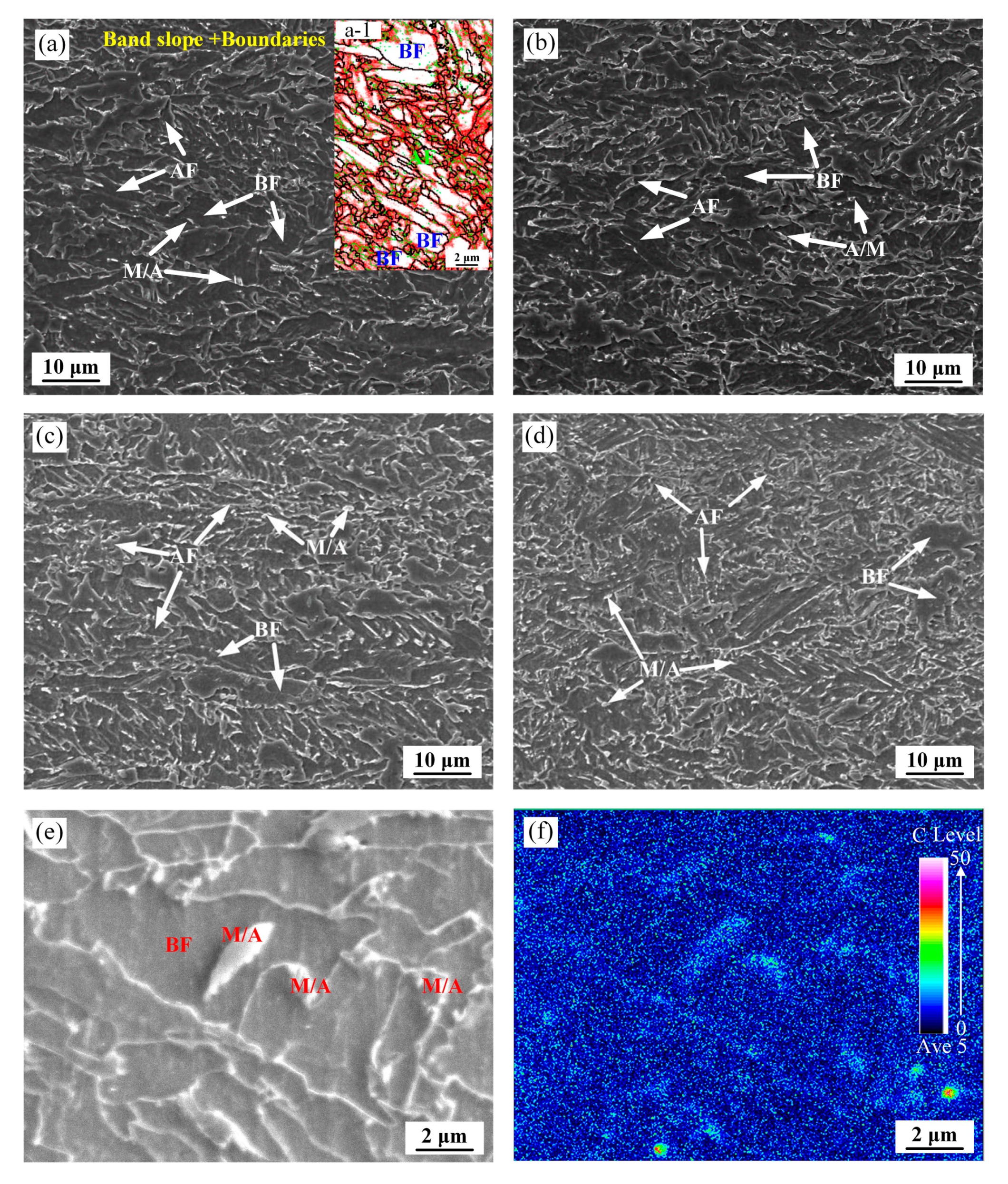
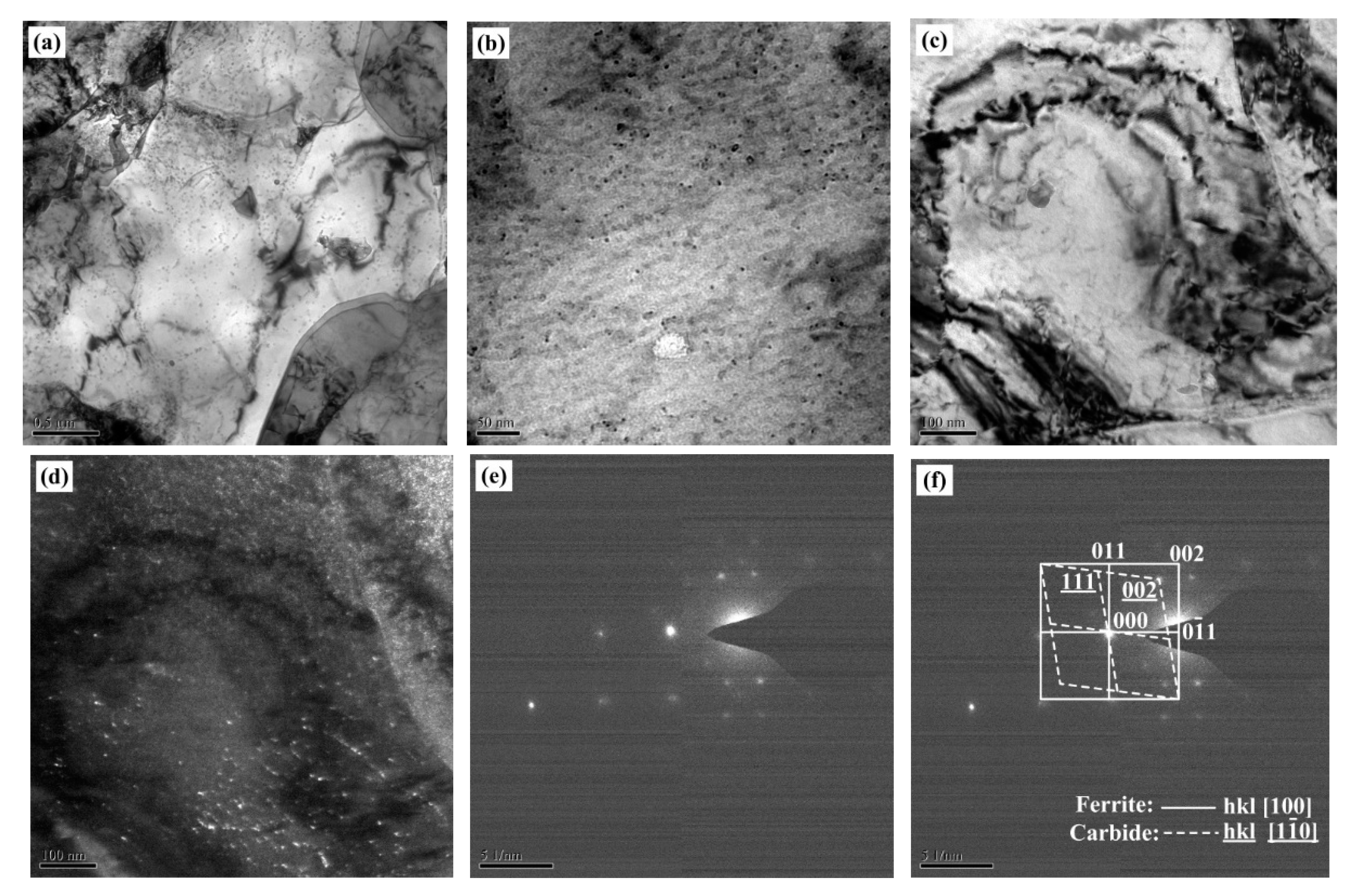
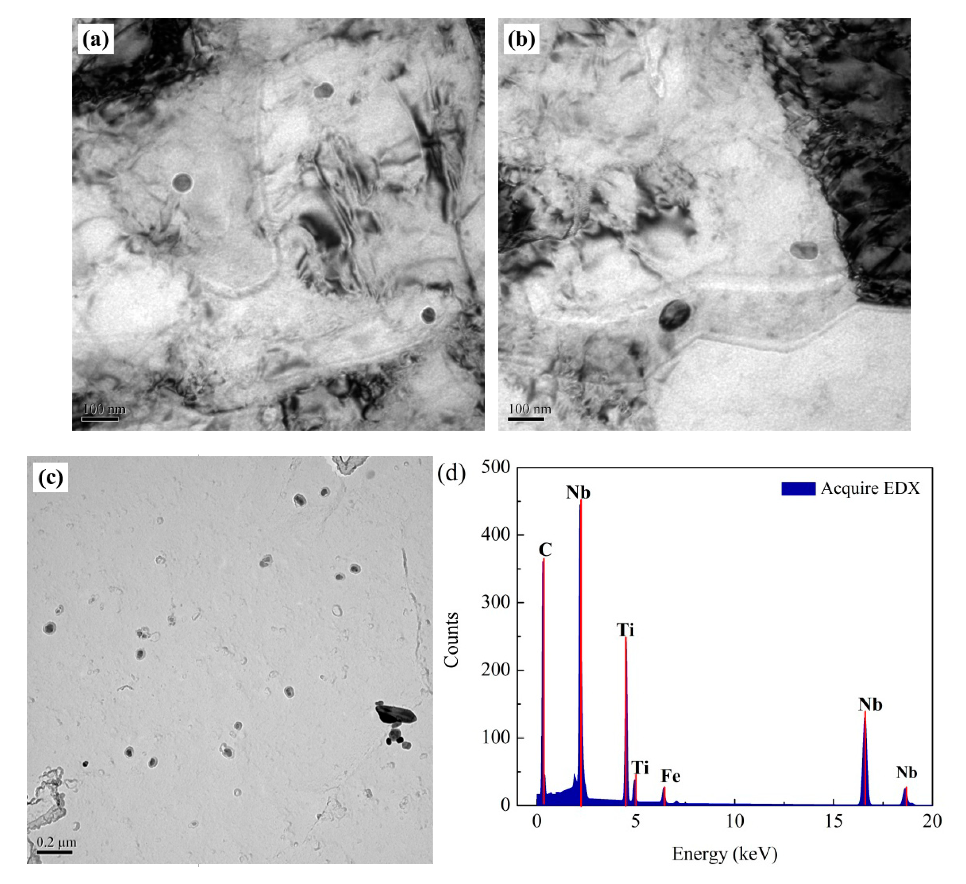
3.1. Microstructural Evolution

Figure 2 shows the scanning electron images of the 25.4 mm X70 pipeline and 22 mm X80 pipeline strips at a quarter and mid-thickness. The microstructures of both pipeline steels were of AF, BF, and fine martensite-austenite (M-A) islands. AF nucleation occurred in the austenite grain interior and its morphology is lath or fine-grained, while. BF nucleation occurred at the grain boundary of the deformed austenite and it has a blocky shape [11,12]. The M-A islands were distributed at BF boundaries or in BF and were rich in carbon, as shown in Figure 2e,f. It is important to quantitatively count the fraction of different phases. The fraction of M-A islands could be easily got through several SEM images combining the EPMA results. However, it is difficult to distinguish the AF and BF due to the same crystal structure of BCC (body-centered cubic), but the shape, size and the quality of Band Contrast/Slope are key information.
As shown in Figure 2(a-1) that combined grain boundaries with band slope image, the BF has a blocky shape, a bigger size and a high band slope value. The observations of Figure 2(a-1) could help us to better define the shape and size of BF. Finally, we could get the fraction of AF and BF based on several high-resolution SEM images. Based on the above analysis, statistics of area fractions of microstructural constituents of X70 and X80 pipeline strips across the thickness were obtained, with the results shown in Table 2.
The microstructure had a uniform distribution across the thickness and the AF fraction in the quarter-thickness reached 90% and 92%, and in the center-thickness reached 85% and 88% respectively, for the X70 and X80 pipeline steels, which indicates a significant increase in AF fraction compared to that processed by conventional TMCP technology, where only contained less than 15% AF [7]. This result implies that UFC can promote AF formation, which ensures the microstructure homogeneity. In addition, the fraction of AF in the quarter-thickness has a small increase compared with that in the center-thickness. This is attributed to the cooling rate and the deformation in the quarter-thickness being slightly higher than that in the center-thickness, which could promote AF nucleation and get more AF. Besides, the difference of finish cooling temperature in the thickness direction and some microstructure statistical error could also make this small difference in AF fraction. Anyway, this result could sufficiently indicate the microstructure homogeneity. In order to get data of grain size and grain boundary, we performed EBSD experiments on center regions of X70 and X80, as shown in Figure 3. Under the UFC condition, the effective grain size of the X70 and X80 pipeline steels was refined to 2.7 µm and 2.4 µm, respectively, whereas the effective grain size of X80 was 4.0 µm in conventional TMCP equipped with a laminar cooling system [7]. The high-angle boundary fraction of X70 and X80 pipeline steels was 43% and 45%, respectively. High-angle grain boundaries (>15°) can block crack propagation, whereas low-angle grain boundaries do not have the same effect [13]. Such a large high-angle boundary fraction could contribute significantly to the toughness.
Figure 4 and Figure 5 show TEM images of the X70 and X80 pipeline steels, respectively. Figure 4a–c shows that fine blocky ferrite and fusiform ferrite were present in the X70 pipeline steel substructure. The blocky ferrite was about 1 μm and the width of fusiform ferrite varies from submicron- to micron-level. A dislocation cell was visible in the cusp of fusiform ferrite as shown in Figure 4a,b. The dark-field image and selected-area electron diffraction (SAED) pattern in Figure 4d–f shows that the substructure of adjacent fusiform ferrite had a similar crystallographic orientation. A low-angle grain boundary was present in different fusiform ferrite substructures. In Figure 5a–c, similar to the substructure of X70 pipeline steel, fine blocky ferrite and fusiform ferrite were observed, and some dislocation cells were observed in fusiform ferrite in X80 pipeline steel. Figure 5d–f shows that the substructure of adjacent fusiform ferrite in X80 pipeline steel also had a similar crystallographic orientation. The fine substructure and low-angle grain boundary can hinder dislocation slip during the deformation, which increases the matrix strength.
Figure 6a–d shows the TEM images of precipitates in the 25.4 mm X70 pipeline strip. There are many nanosized carbides (10–20 nm) distributed in the α-matrix and few carbides have sizes of dozens of nanometers, as shown in Figure 6c. Based on the bright-field and dark-field images (Figure 6c,d), these precipitates have a similar crystallographic orientation. The SAED pattern (Figure 6e,f) shows that the crystallographic orientation between the precipitates and the α-matrix is Baker–Nutting. Thus, nanosized precipitates formed in the α-matrix during heat preservation.
Figure 7a–c shows TEM images of precipitates in the 22 mm X80 pipeline strip. It has a huge difference from precipitates of X70. In X80 pipe steel, most of the precipitates were 40–60 nm, and it was difficult to observe fine precipitates of 10 nm. The EDS results in Figure 7d indicate that the precipitate was (Nb, Ti)(C, N). Based on the TMCP, it can be inferred that the solubility of Nb and Ti in austenite decreased in the finish rolling stage at 810 °C. Under this condition, strain-induced precipitation of (Nb, Ti)(C, N) occurred. The precipitation coarsened during return-red of rolling and coiling processes and finally, it was present at 40–60 nm.

3.2. Mechanical Propertiesres

Table 3 and Table 4 show the typical mechanical properties of 25.4 mm X70 and 22 mm X80 pipeline strip steels processed by UFC. The tensile properties of two steels satisfy the API SPEC 5L standards and achieved excellent low-temperature toughness and crack arrest property. The impact-absorbing energy of X70 and X80 exceeds 300 J above –20 °C, which satisfies the API SPEC 5L standards, and it can be inferred that the ductile-brittle transition temperature for the two steels was below –60 °C. The DWTT shearing area of the 25.4 mm X70 pipeline strip and 22 mm X80 pipeline steel was above 90%. Thus, the two steels achieved excellent mechanical properties and a good combination of strength and toughness.

4. Discussion

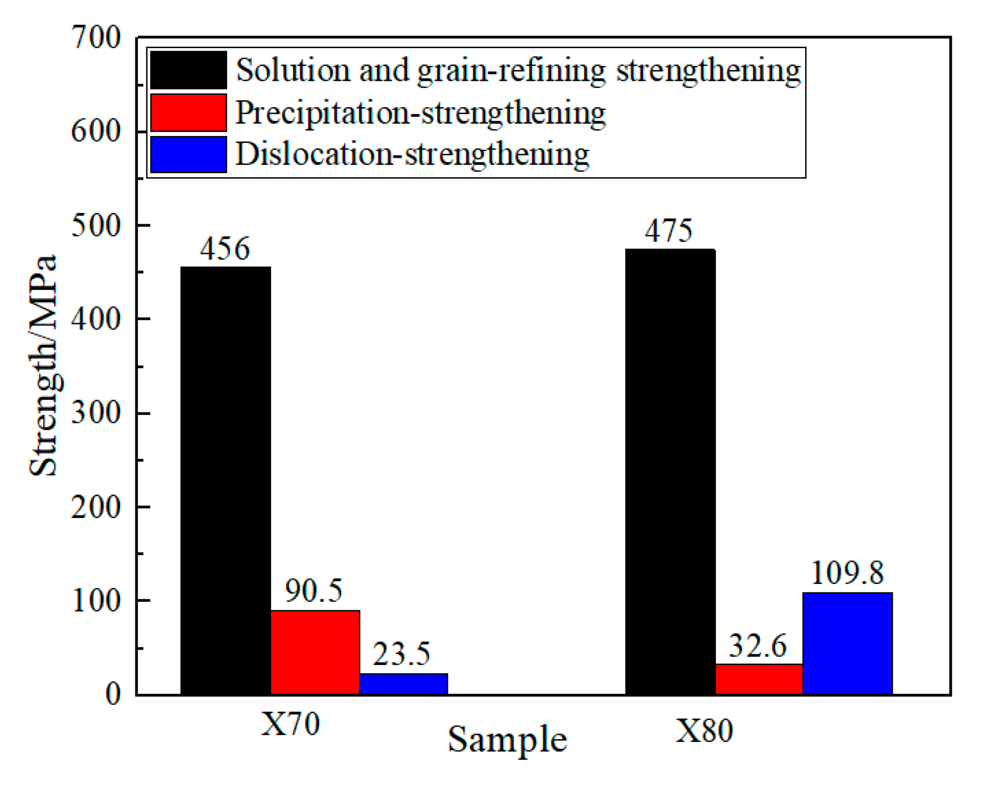
4.1. Strengthening Mechanisms of X70/X80 Pipeline Steels under UFC

The yield strength tends to depend on different contributions, including the grain-refining strengthening, dislocation strengthening, solid–solution strengthening and precipitation strengthening [14]. Equation (1) was used to calculate the yield strength [15]:
( MPa ) = σ y = σ 0 + σ ss + σ sg + σ ρ 2 + σ p 2 ,
where σ0 + σss is the solid-solution strengthening contribution, σsg is the grain-refining strengthening contribution, σρ is the dislocation strengthening contribution and σp is the precipitation strengthening contribution.
To elucidate the strengthening mechanism of 25.4 mm X70 and 22 mm X80 pipeline steels, relevant theoretical model and experimental results were used to calculate the strengthening contribution that was obtained by the corresponding strengthening mechanism.
The contributions of the solution and grain-refining strengthening were calculated by using the modified Hall-Petch theory, as shown in Equation (2) [16]:
Δ σ g ( MPa ) = 15.4 { 3.5 + 2.1 Mn + 5.4 Si + 23 N f + 1.13 d 1 / 2 }
where Mn, Si and Nf are the concentrations of elemental Mn, Si and N (wt%), respectively, and d is the effective grain size. N may present in the precipitation because the studied steel contained a certain amount of microalloy elements (Nb, V and Ti) that consumed N significantly. Thus, the N content dissolved in the matrix was ignored in Equation (2). Δσg equaled σ0 + σss + σsg in Equation (1).
The contribution of precipitation strengthening was calculated by using the classical Ashby-Orowan equation [17]:
σ p = ( 0.538 G b f 0.5 / X ) * ln ( X / 2 b )
where G, b, f and X are the shear elasticity, Burgers vector, volume fraction and precipitate size, respectively. G and b are constant quantities, and the values were 80,000 MPa and 0.248 nm. Because of the small size of nano precipitates, the SEM image cannot present the precipitates clearly and the TEM image is suitable for the quantitative analysis of nano precipitates. To obtain accurate statistical results, dozens of high-magnification TEM images were randomly selected. Since the precipitates were not uniform, especially for large sizes exceeding 40 nm in X80 steel, some TEM images contained more precipitates and some contained less, as shown in Figure 7. The size of precipitates was calculated by the average diameter of hundreds of precipitates, and the volume fraction of precipitates was calculated based on the area ratio of precipitates and the thin zone of TEM specimen (50–120 nm). Finally, we could get the size and volume fraction of precipitates for X70 and X80 steels, and they were 13.5 nm, 0.12% and 50 nm, 0.11%, respectively. It should be noted that these calculated values also have statistical error, but it is enough to distinguish the precipitation strengthening contribution for X70 and X80 steels.
According to the theoretical equation, the strength contribution that was induced by different strengthening mechanisms of 25.4 mm X70 and 22 mm X80 pipeline steels was calculated in Figure 8. The contribution of the solution and grain-refining strengthening of the 25.4 mm X70 pipeline steel was 456 MPa, which is lower than the 22 mm X80 pipeline steel (475 MPa). For this calculation, 1.6%Mn, 0.19%Si and 2.7 μm for X70 steel, and 1.75%Mn, 0.11%Si and 2.4 μm for X80 steel were adopted based on Equation (2). The precipitation-strengthening contribution in the X70 pipeline steel was 90.5 MPa, whereas that in the X80 pipeline steel was decreased to 32.6 MPa, because of the large size of precipitates. This calculation was based on the above statistical results of precipitates, where the size and volume fraction were 13.5 nm, 0.12% and 50 nm, 0.11%, respectively, for X70 and X80 steels. In addition, because of the difficulty in measurement of the accurate dislocation density, the dislocation-strengthening contribution was deduced by Equation (1) and the yield strength. Finally, the dislocation-strengthening contribution of the 25.4 mm X70 pipeline steel was 23.5 MPa, which was much lower than that of the 22 mm X80 pipeline steel (109.8 MPa).
The strengthening mechanisms of 25.4 mm X70 and 22 mm X80 pipeline steels differed, depending on the TMCP process and alloy composition system. The Mn content in the 25.4 mm X70 pipeline steel was lower than that in the 22 mm X80 pipeline steel. Mn is the main element that is responsible for solid-solution strengthening in pipeline steel. Because no obvious difference was observed in the effective grain size of the two pipeline steels, the contribution of solution and grain-refining strengthening of the 25.4 mm X70 pipeline steel was lower than that of the 22 mm X80 pipeline steel. Precipitates below 20 nm were observed in the 25.4 mm X70 pipeline steel matrix, whereas only precipitates above 40 nm were observed in the 22 mm X80 pipeline steel. This difference was caused by the following reasons. Precipitation behavior in the pipeline steel was related to the solubility product of microalloy elements (chemical composition) and holding temperature (coiling temperature). First, the finishing rolling temperature of X80 steel was 810 °C, whereas it was 840 °C for X70 steel. In the low-temperature deformation, it was easier to induce strain-induced precipitation, which formed more precipitates of X80 at high temperature. Figure 9 shows the phase volume fraction variation of (Nb,Ti)(C,N) and cementite for 300–1200 °C, and the calculated weight percentage variation of Nb, Ti, C and N for 300–1100 °C from Thermo-Calc software 2017b combined with the TCFE9 database (Stockholm, Sweden). The variation in (Nb,Ti)(C,N) precipitation and elemental Nb, Ti, C and N was almost the same in the controlled rolling stage of both steels. However, below 800 °C, cementite formed easily in 22 mm X80 pipeline steel. In addition, the precipitation behavior was also related to the return-red phenomenon for heavy gauge pipeline steels. The coiling temperatures were the same for X70 and X80 pipe steels, but the return-red phenomenon was more obvious for X70 because of the heavier thickness of 25 mm, which was beneficial for the formation of nano-sized precipitates. For X80 pipe steel, the precipitates induced by strain will coarsen. However, the more obvious return-red phenomenon would reduce the dislocation-strengthening contribution. Besides, the higher finish rolling temperature of 840 ℃ for X70 also reduced the dislocation strengthening contribution. Therefore, a small dislocation strengthening contribution of ~23.5 MPa was obtained in X70 steel. This synergy effect of return-red phenomenon has been discussed in previous study [18] and could exactly explain the different strengthening contributions for X70 and X80 pipe steels.

4.2. Effect of TMCP Process on Microstructure and Toughening Mechanism

The low-temperature toughness of pipeline steel is related to the material microstructure. The typical organization includes AF/BF/GB and M/A, and the pipeline steel with mainly AF has an excellent low-temperature impact toughness because its effective grain size is fine. The X70 and X80 pipeline steels under UFC process achieved a fine AF microstructure, and the distribution was uniform along the thickness direction.
In the TMCP process, the phase transformation of AF and BF was linked to the alloy composition system and controlled rolling and cooling parameters. A larger deformation in the controlled rolling process and a higher cooling rate in the controlled cooling process provides enough nucleation positions and a larger phase transformation driving force for AF. Thus, an AF-dominant microstructure and a smaller effective grain size could be obtained.
During ductile fracture, cracks can deflect and expand the crack-extension energy when AF is encountered, which ensures that the material has good toughness. Therefore, the main toughening mechanism of 25.4 mm X70 and 22 mm X80 steels under the UFC process is as follows: UFC promoted the AF group formation, decreased the material grain size, increased the grain boundary length per unit area and increased the probability of crack deflection. These changes ensured that the material had an excellent low-temperature toughness and crack resistance.
In summary, although the 25.4 mm X70 and 22 mm X80 pipeline steels in the UFC process had a similar alloy composition and similar cooling process parameters, their strengthening mechanisms differed. The main strengthening mechanism of 25.4 mm X70 pipeline steel is a combination of fine-grain strengthening, solid-solution strengthening, and precipitation strengthening. However, the precipitation-strengthening mechanism of 22 mm X80 pipeline steel is only 32.6 MPa, because of the large size of precipitates of 40–60 nm. Therefore, the strengthening mechanism of X80 pipeline steel is a combination of fine-grain strengthening, solid-solution strengthening and dislocation strengthening. During the development of pipeline steel with a higher strength by UFC or an optimization of the existing pipeline steel composition system, the coupling effect of grain-refining strengthening, dislocation strengthening and nanoprecipitation strengthening should be considered. By clarifying the process conditions of nanosize precipitation formation under UFC and by improving the material strength through optimizing its composition system, the low-cost, high-benefit, improved quality and high-efficiency pipeline steel production can be achieved.

5. Conclusions

Excellent mechanical properties were obtained for 25.4 mm X70 and 22 mm X80 pipeline steels in the UFC process. The microstructures of the 25.4 mm X70 and 22 mm X80 pipeline steels consisted of BF, AF and M-A islands. The average effective grain sizes of the X70 and X 80 steels were 2.7 μm and 2.4 μm, respectively. High-angle grain boundary fractions of the two steels were 43% and 45%, respectively. The large fraction of AF and small grain size of X70 and X80 steel ensured a high qualification rate of DWTT and good toughness with a ductile-brittle transition temperature below −60 ℃. The main strengthening mechanism for 25.4 mm X70 pipeline steel was the solution and grain-refining strengthening, and precipitation strengthening with contributions of ~456 MPa and ~90.5 MPa, respectively. The dislocation strengthening was only 23.5 MPa in X70 steel. The main strengthening mechanism for 22 mm X80 pipeline steel was the solution and grain-refining strengthening, and dislocation strengthening with contributions of ~475 MPa and ~109.8 MPa, respectively. The precipitation strengthening contribution in X80 steel was only 32.6 MPa. The reason for small precipitation strengthening for X80 pipe steel is duo to strain-induced precipitation and precipitate coarsening during return-red process.

Author Contributions

Conceptualization, G.Y. and G.-d.W.; methodology, X.-q.W. and J.-h.Z.; investigation, X.-q.W. and J.-h.Z.; resources, G.Y. and G.-d.W.; data curation, X.-q.W.; writing—original draft preparation, X.-q.W.; writing—review and editing, J.-h.Z. and G.Y.; supervision, G.Y. and G.-d.W.; project administration, G.Y.; All authors have read and agreed to the published version of the manuscript.

Funding

This research was funded by the Joint Funds of the National Natural Science Foundation of China (U1860201).

Acknowledgments

We thank Laura Kuhar for editing the English text of a draft of this manuscript.

Conflicts of Interest

The authors declare no conflict of interest.

References

  1. Zhou, X.G.; Zeng, C.Y.; Yang, H.; Ma, L.Y.; Liu, Z.Y.; Wu, D.; Wang, G.D. Effect of cooling process on microstructure and mechanical properties of X100 pipeline steel. Steel Res. Int. 2016, 87, 1366–1375. [Google Scholar] [CrossRef]
  2. Liu, Z.Y.; Li, Q.; Cui, Z.Y.; Wu, W.; Li, Z.; Du, C.W.; Li, X.G. Field experiment of stress corrosion cracking behavior of high strength pipeline steels in typical soil environments. Constr. Build. Mater. 2017, 148, 131–139. [Google Scholar] [CrossRef]
  3. Shim, D.J.; Uddin, M.; Wilkowski, G. Comparison between standard and modified back-slotted DWTT specimens. In Proceedings of the 2014 10th International Pipeline Conference, Calgary, AB, Canada, 29 September–3 October 2014. [Google Scholar]
  4. Yu, P.S.; Ru, C.Q. Analysis of energy absorptions in drop-weight tear tests of pipeline steel. Eng. Fract. Mech. 2016, 160, 138–146. [Google Scholar] [CrossRef]
  5. Zhao, J.; Wang, X.Q.; Kang, J.; Yuan, G.; Di, H.S. Crack propagation behavior during DWTT for X80 pipeline steel processed via ultra-fast cooling technique. Chin. J. Mater. Res. 2017, 31, 728–736. [Google Scholar] [CrossRef]
  6. Kang, M.; Kim, H.; Lee, S.; Shin, S.Y. Effects of Dynamic Strain Hardening Exponent on Abnormal Cleavage Fracture Occurring During Drop Weight Tear Test of API X70 and X80 Linepipe Steels. Metall. Mater. Trans. A 2013, 45, 682–697. [Google Scholar] [CrossRef] [Green Version]
  7. Yuan, G.; Hu, W.L.; Wang, X.Q.; Kang, J.; Zhao, J.H.; Di, H.S.; Wang, G.D. The relationship between microstructure, crystallographic orientation, and fracture behavior in a high strength ferrous alloy. J. Alloys Compd. 2017, 695, 526–539. [Google Scholar] [CrossRef]
  8. Costin, W.L.; Lavigne, O.; Kotousov, A.; Ghomashchi, R.; Linton, V. Investigation of hydrogen assisted cracking in acicular ferrite using site-specific micro-fracture tests. Mater. Sci. Eng. A 2016, 651, 859–868. [Google Scholar] [CrossRef] [Green Version]
  9. Xiong, Z.; Liu, S.; Wang, X.; Shang, C.; Li, X.; Misra, R.D.K. The contribution of intragranular acicular ferrite microstructural constituent on impact toughness and impeding crack initiation and propagation in the heat-affected zone (HAZ) of low-carbon steels. Mater. Sci. Eng. A 2015, 636, 117–123. [Google Scholar] [CrossRef]
  10. Zhou, M.W.; Yu, H. Influences of Microstructure and Texture on Toughness of Acicular Ferrite Pipeline Steel. Adv. Mater. Res. 2011, 399–401, 245–249. [Google Scholar] [CrossRef]
  11. Yamamoto, S.; Yokoyama, H.; Yamada, K.; Niikura, M. Effects of the Austenite Grain Size and Deformation in the Unrecrystallized Austenite Region on Bainite Transformation Behavior and Microstructure. ISIJ Int. 1995, 35, 1020–1026. [Google Scholar] [CrossRef] [Green Version]
  12. Kim, Y.; Lee, H.; Kim, N. Transformation behavior and microstructural characteristics of acicular ferrite in linepipe steels. Mater. Sci. Eng. A 2008, 478, 361–370. [Google Scholar] [CrossRef]
  13. Zhou, P.; Zhou, J.; Ye, Z.; Hong, X.; Huang, H.; Xu, W. Effect of grain size and misorientation angle on fatigue crack growth of nanocrystalline materials. Mater. Sci. Eng. A 2016, 663, 1–7. [Google Scholar] [CrossRef]
  14. Kim, Y.W.; Song, S.W.; Seo, S.J.; Hong, S.-G.; Lee, C.S. Development of Ti and Mo micro-alloyed hot-rolled high strength sheet steel by controlling thermomechanical controlled processing schedule. Mater. Sci. Eng. A 2013, 565, 430–438. [Google Scholar] [CrossRef]
  15. Kim, B.; Boucard, E.; Sourmail, T.; San Martín, D.; Gey, N.; Rivera-Díaz-del-Castillo, P.E.J. The influence of silicon in tempered martensite: Understanding the microstructure–properties relationship in 0.5–0.6 wt.% C steels. Acta Mater. 2014, 68, 169–178. [Google Scholar] [CrossRef]
  16. Pickering, F.B. Physical Metallurgy and the Design of Steels; Applied Science Publishers Ltd.: London, UK, 1978. [Google Scholar]
  17. Gladman, T. Precipitation hardening in metals. Mater. Sci. Technol. 1999, 15, 30–36. [Google Scholar] [CrossRef]
  18. Li, Z.L.; Chen, D.; Li, Y.J.; Wang, X.Q.; Kang, J.; Yuan, G. A novel process involving multiple strengthening mechanisms for production of low-residual stress X80 pipe steel based on ultra-fast cooling. Mater. Lett. 2019, 257, 126767. [Google Scholar] [CrossRef]
Figure 1. Schematic diagram of thermomechanical-controlled processing (TMCP) for the studied steel.
Metals 10 01323 g001
Figure 2. Scanning electron morphology of: (a,b) 25.4 mm X70 pipeline strip at quarter and mid-thickness, (c,d) 22 mm X80 pipeline strip at quarter- and mid-thickness and (e,f) the distribution of M-A islands and carbon mapping at quarter-thickness of X70.
Metals 10 01323 g002
Figure 3. Grain boundary maps of the center region of X70 (a,c) and X80 (b,d). The black lines indicate the high-angle grain boundaries (>15°) and the red lines indicate the low-angle grain boundaries (<15°).
Metals 10 01323 g003
Figure 4. Micrographs from transmission electron microscope (TEM) observation for 25.4 mm X70 pipeline strip: (ac) substructure, (d) dark-field micrograph of parallel microstructure, and (e,f) corresponding diffraction spots.
Metals 10 01323 g004
Figure 5. Micrographs from TEM observation for 22 mm X80 pipeline strip: (ac) substructure, (d) dark-field image of parallel microstructure, and (e,f) corresponding diffraction spots.
Metals 10 01323 g005
Figure 6. Precipitation observation of 25.4 mm X70 pipeline strip: (ac) morphology of precipitates, (d) dark field image of precipitates, (e,f) crystallographic orientation between matrix and precipitates.
Metals 10 01323 g006
Figure 7. Precipitation morphology of 22 mm X80 pipeline strip processed by ultrafast cooling (UFC). (a)–(c) are morphology of precipitates. (d) is energy spectrum of precipitate.
Metals 10 01323 g007
Figure 8. Strengthening contributions of X70 and X80.
Metals 10 01323 g008
Figure 9. Calculated results obtained using Thermo-Calc software. (a) phase volume fraction variation with temperature; (b) element weight percent in precipitation variation with temperature.
Metals 10 01323 g009
Table 1. Chemical composition of steel (wt.%).
SteelCPSMnSiNb + V + TiCu + Ni + MoCrFe
X700.0440.0120.0011.600.190.120.620.16Bal.
X800.0610.0130.0011.750.110.110.520.27Bal.
Table 2. Area fractions of microstructural constituents of X70 (25.4 mm) and X80 (22 mm) pipeline strips across the thickness.
No.AFBF + M/AObserved Position
X70-UFC9010Quarter-thickness
8515Mid-thickness
X80-UFC928Quarter-thickness
8812Mid-thickness
Table 3. Typical mechanical properties of 25.4 mm X70 and 22 mm X80 pipeline strip processed by UFC.
No.Tensile PropertyDWTT/%
Rt0.5
/MPa
Rm
/MPa
Elongation
/%
Specimen 1Specimen 2Average
25.4 mm X70549.568721909592.5
API SPEC X70500–625570–700≥16–15°C, single ≥ 80%, average ≥ 85%
22 mm X80589.5710.2239010095
API SPEC X80555–690625–825≥16–15°C, single ≥ 80%, average ≥ 85%
Table 4. Impact energy of X70 and X80.
No.–20 °C–40 °C–60 °C–80 ℃–120 °C
25.4 mm X70413 ± 7 J387 ± 12 J311 ± 10 J200 ± 1220 ± 4
22 mm X80305 ± 3 J300 ± 5 J279 ± 15 J125 ± 1411 ± 3
API SPEC 5L–20 °C, single ≥ 160 J, average ≥ 200 J

