Article

Experimental and Numerical Investigation of Reaction Behavior of Carbon Composite Briquette in Blast Furnace

State Key Laboratory of Advanced Metallurgy, University of Science and Technology Beijing, Beijing 100083, China
*
Author to whom correspondence should be addressed.
Metals 2020, 10(1), 49; https://doi.org/10.3390/met10010049
Submission received: 30 November 2019 / Revised: 19 December 2019 / Accepted: 20 December 2019 / Published: 25 December 2019
(This article belongs to the Special Issue Mathematical Modeling and Simulation in Ironmaking and Steelmaking)

Abstract

:
The application of carbon composite briquette (CCB) is considered to be an efficient method for achieving low-energy and low-CO2-emission blast furnace (BF) operations. In this research, a combined experimental and numerical study was conducted on the CCB reaction behavior in BF. The CCB used in this study had a composition of 20.10 wt.% carbon, 29.70 wt.% magnetite, 39.70 wt.% wüstite, and 1.57 wt.% metallic iron. Using the prepared CCB samples, isotherm reduction tests under a simulated BF atmosphere (CO-CO2-N2) were conducted and a reaction model was developed. Subsequently, the reaction behavior of CCB along the mid-radial solid descending path in an actual BF of 2500 m3 was analyzed by numerical simulations based on the experimental findings and the previous results of comprehensive BF modeling. The results of the experiments showed that the CCB model predictions agreed well with the experimental measurements. With respect to the BF, the results of the numerical simulations indicated that, along the path, before the CCB temperature reached 1000 K, the CCB was reduced by CO in the BF gas; when its temperature was in the range from 1000 to 1130 K, it underwent self-reduction and contributed both CO and CO2 to the BF gas; when its temperature was above 1130 K, it only presented carbon gasification. Moreover, these results also revealed that the reduction of iron oxide and the gasification of carbon inside the CCB proceeded under an uneven mode. The uneven radial distribution of the local reduction fraction and local carbon conversion were evident in the self-reducing stage of the CCB.

1. Introduction

In the foreseeable future, the traditional manufacturing route (i.e., blast furnace (BF) ironmaking and basic oxygen furnace (BOF) steelmaking) will continue to be predominant methods for producing iron and steel across the world [1]. Although these processes are well-established and highly efficient, they face challenges related to lowering energy consumption and minimizing CO2 emissions that are needed to create a more efficient and sustainable iron and steel industry. As the BF sector accounts for 75%–80% of the total energy consumption and it generates the largest amount of CO2 emissions [2,3] finding ways for the BF industry to conform to these environmentally standards is crucial.
Applying carbon composite briquette (CCB) in a BF is considered to be an effective method to achieve energy-saving and CO2 emission reduction [4]. In general, CCB comprises iron-bearing oxide and carbonaceous materials in general. Using CCB as a partial charge in a BF offers the benefits of (1) less sintering and coking processes [5,6], (2) the effective use of non-coking coal and iron-bearing dust and sludge [7], (3) faster reduction of iron oxide [8,9], and (4) the decrease of BF energy consumption [10]. Several methods have been proposed to prepare CCB with sufficient high-temperature strength in a BF. The major methods are cold briquetting with cement as a binder [11,12], hot briquetting using fused coal [13,14], and cold briquetting followed by heat treatment [15,16]. Some of these methods have been adopted in industrial BF practices [11,17]. Presently, studies on CCB have shifted to CCB behavior in a BF and its influence on the BF in-furnace phenomena. These studies can help the iron producers to use CCB more efficiently in a BF. CCB behavior in a BF covers reaction behavior, melting behavior, carburization mechanism, etc. The reaction behavior of CCB can be of fundamental importance because it is closely related to the changes of ore reduction and of coke gasification in the upper part of a BF. Most studies on CCB reaction behavior have been carried out under simulated BF in-furnace conditions [18,19,20]. However, the high-pressure environment in a BF was generally overlooked in these studies. This could have been because of the limitation of experimental devices.
Mathematical modeling is an effective tool for understanding the CCB reaction behavior in an actual BF. Reaction models of the CCB have already been extensively studied. However, most of these models were aimed to give an understanding of the CCB behavior in direct reduction processes (e.g., rotary hearth furnace process). Liu et al. [21] developed a 3D unsteady model with consideration of heat transfer, mass transfer, and chemical reactions in the CCB. Sun and Lu [22] contributed a non-isothermal model which consists of 19 independent equations. Shi et al. [23] proposed a model with the consideration of both conductive and convective heat transfer. Donskoi et al. [24] built a model including the swelling/shrinkage of the CCB. Tang et al. [25] gave a model for the CCB reduction under the oxidative atmosphere. These models were mainly constructed on the concept of a discrete system with particles in CCB exhibiting diffusion and reaction phenomena and were sufficient for analyzing the reaction behavior of a single CCB. However, these models were suitable for the CCB reaction under normal pressure, oxidative or inert atmosphere. Therefore, they could not be used to model the CCB reaction under the BF conditions, which were with high pressure and reducing atmosphere. Reaction models involved in the CCB reaction in BF are few. Chu et al. [26] developed a model by simplifying the stage-wise reduction of iron oxide to a one-step reaction from hematite to metallic iron. Ueda et al. [27] proposed a model assuming that the development of reactions inside CCB is uniformly profiled. Although their models can be easily integrated into the total BF model, they did not comply with the CCB reaction mechanism, thereby leading to a failure in capturing the details of CCB reaction behavior in BF and some errors in understanding.
In this study, a combined experimental and numerical study was conducted to investigate the CCB reaction behavior in actual BF conditions. The CCB samples were prepared by cold briquetting followed by heat treatment. The CCB samples were characterized in terms of chemical analysis, microstructure analysis, phase identification, and subjected to isothermal reduction under simulated BF conditions. The kinetics of CCB reaction was modeled based on the conservation of gas species and solid species inside the CCB. The basic properties of CCB and the developed CCB model were then applied for studying the reaction behavior of CCB along the mid-radial solid descending path in a BF of 2500 m3. Changes of CCB reduction fraction, CCB carbon conversion, and radial distributions of local parameters along the path were examined. The aim of this study was to reveal correctly the CCB reaction behavior along a typical burden descending path in BF and to provide an effective method for designing and optimizing CCB charge operation in BF.

2. Experimental

2.1. Raw Materials

The raw materials were hematite fines, quartz fines, and coal fines. The quartz fines were employed as additives. The hematite fines and the quartz fines were chemical reagents that were purchased from Sinopharm Co. (Shanghai, China), and the coal fines were provided by BF pulverized coal injection (PCI) sector of an iron and steel company in China. The average size of the hematite fines, quartz fines, and coal fines were 2.0, 2.5, and 94.0 µm, respectively. The properties of the coal fines are shown in Table 1.

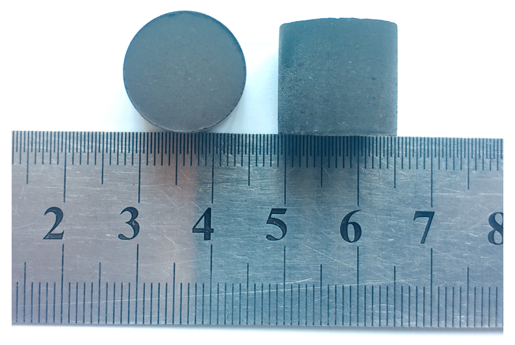
2.2. CCB Preparation

The CCB samples were prepared using cold briquetting followed by heat treatment [15,16]. The hematite fines, quartz fines, and coal fines were thoroughly mixed under a mass ratio of hematite:Quartz:coal = 67:3:30. After the addition of 10.0% distilled water and 2.0% organic binder (cellulose), the briquettes were made by pressing the moistened fines using a steel die under a pressure of 15 MPa. The briquettes were dried in the air followed by drying at 423 K and were then hardened by heat treatment. The heat treatment was conducted using a tubular furnace under a N2 atmosphere. The thermal route was defined in the following manner. The furnace was heated from room temperature to 1073 K at a rate of 5 K/min. After reaching the heating temperature for 30 min, the furnace was naturally cooled. The prepared CCB samples were subjected to chemical analysis, microstructure examination, and phase identification.

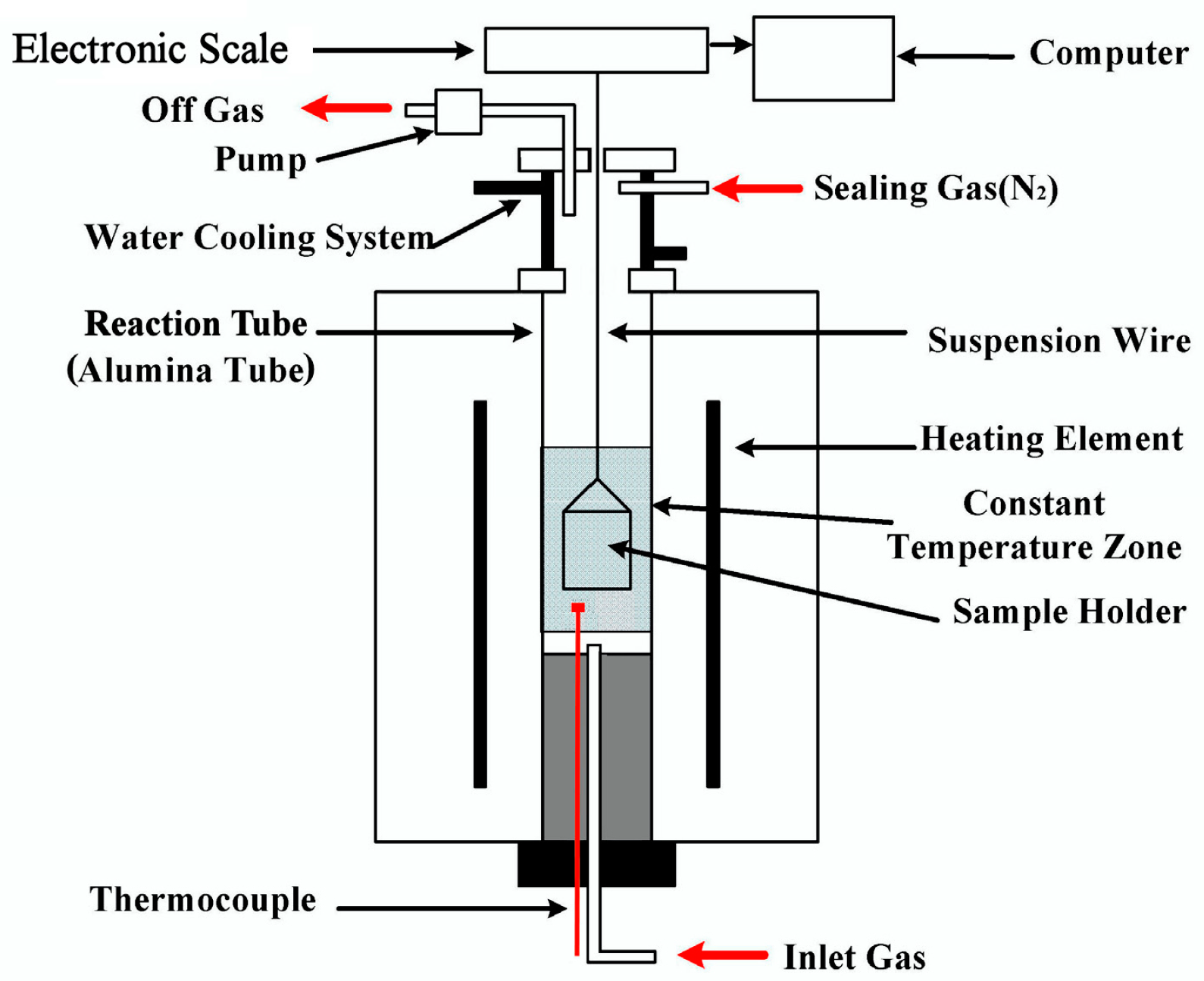
2.3. CCB Reaction Tests

The experimental setup is schematically shown in Figure 1 and has been detailed elsewhere [23]. The following is an outline. The device comprised a gas supply system, an electronic balance with an accuracy ±0.001 g, and a temperature-controlled furnace with an accuracy of ±2 K. The furnace was heated by MoSi2 elements producing a 50 mm hot zone in the reaction tube with an inner diameter of 55 mm. The sample holder was made of a heat-resistance alloy (Fe-Cr-Al) wire.
In the tests, the furnace was first preheated to the reaction temperature under a N2 atmosphere by introducing N2 at the inlet until the temperature became stable. After the sample was preheated to 773 K for approximately 5 min in the upper part of the reaction tube, it was introduced into the constant temperature zone and N2 was switched to a N2-CO-CO2 mixture. When the sample was introduced into the hot zone, the mass of the sample was measured by the balance and recorded every two seconds by the logging computer. After a predetermined time, the N2-CO-CO2 gas mixture was switched back to N2 and the briquette sample was withdrawn from the furnace and quenched using N2. For each run, a single CCB sample was loaded and the total gas flow rate was 3000 mL/min (STP). After the heat treatment, the volatile matter in the CCB samples could be completely removed; therefore, the mass-loss degree of the sample at time t was calculated by ( m 0 m ) / ( m O , 0 + m C , 0 ) where m is the mass of the CCB sample at time t, and m0, mO,0, mC,0 are the mass, iron-oxide oxygen mass, and carbon mass of the initial CCB sample, respectively. mO,0 and mC,0 were determined by the initial composition of the CCB sample. The CCB samples after reaction were subjected to the analysis of reduction fraction and carbon conversion.

2.4. Analysis and Characterization

Techniques used for analysis and characterization of the CCB samples are the following. Carbon content (WC) was measured using a CS-2800 infrared carbon sulfur analyzer (NCS Co., Beijing, China), and contents of total iron (TFe), metallic iron(WFe), and Fe2+ ion (WFe2+) were determined using the titrimetric method (iron chloride method). The microstructure of CCB sample’s cross-section was observed using a Quanta-250 scanning electron microscope (SEM, FEI Co., Hillsborough, OR, USA). Phase identification was performed using an M21X x-ray diffractometer (XRD, MAC Science Co., Tokyo, Japan). The reduction fraction and carbon conversion of the CCB sample after reaction were calculated via 1.0 ( 1.5 ( T Fe W Fe 2 + W Fe ) + W Fe 2 + ) / ( 1.5 T Fe ) and 1.0 ( m W C ) / m C , 0 , respectively.

3. Development of a CCB Model in BF Atmosphere
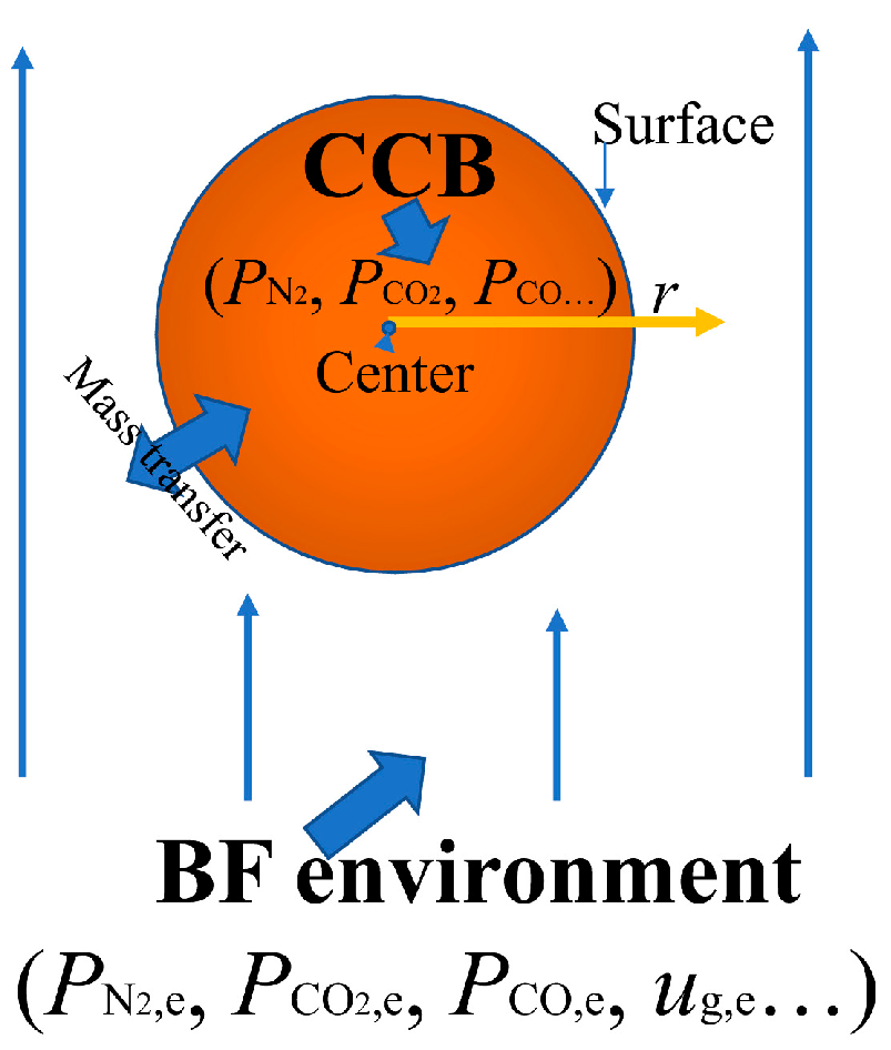
3.1. Theory

A CCB reaction model was established for the reaction of a single CCB in BF atmosphere. The model was based on the conservation of gas and solid species inside the CCB, and the mass transfer between the CCB and the environment. The concept of the model is shown in Figure 2. As the diameter and the height of each CCB were effectively the same, the shape of the CCB was considered to be spherical. The model was thus one dimensional in radial direction. The gas phase in the model was an ideal gas, and the gas-phase species included CO, CO2, and N2. Solid phase species were Fe2O3, Fe3O4, FeO, Fe, and C. Other assumptions in the model development were: (1) the CCB volume was constant throughout the reaction process and (2) the mass transfer by convection was not considered, and (3) the involved reactions were those given in Table 2.
The governing equations of the gas phase were built based on the mass conservation of CO and CO2 inside the CCB.
( α P co 2 ) t = 1 r 2 r ( r 2 D CO 2 - N 2 , eff P co 2 r ) + R T ( R 1 + R 2 + R 3 R 4 )
( α P co ) t = 1 r 2 r ( r 2 D CO - N 2 , eff P co r ) + R T ( 2 R 4 R 1 R 2 R 3 )
D eff , CO - N 2 and D eff , CO 2 - N 2 in Equations (1) and (2) depend on the porous structure of the CCB. They were determined using Equations (3) and (4) [30].
D eff , CO - N 2 = D CO - N 2 α 2 / 3
D eff , CO 2 - N 2 = D CO 2 - N 2 α 2 / 3
where D CO - N 2 and D CO - N 2 are calculated using the method suggested by Natshi [29] with α = 0.5 [23].
For Equations (1) and (2), the boundary conditions are given in Equations (5)–(7) [31], and the initial conditions are shown in Equation (8).
r = 0 ; P CO r = 0 , P CO 2 r = 0
r = d / 2 ; D eff ,   CO - N 2 P CO r = ( D CO - N 2 ( 2.0 + 0.6 Re 1 / 2 Sc CO - N 2 1 / 3 ) / d ) ( P CO P CO , e )
r = d / 2 ; D eff ,   CO 2 - N 2 P CO 2 r = ( D CO 2 - N 2 ( 2.0 + 0.6 Re 1 / 2 Sc CO 2 - N 2 1 / 3 ) / d ) ( P CO 2 P CO 2 , e )
  t = 0 ,   r ( 0 , d / 2 ) ; P CO 2 = P CO 2 , e   ,   P CO 2 = P CO 2 , e
where Re = u g , e ρ g , e d / μ g , e , Sc CO - N 2 = μ g , e / ( ρ g , e D CO - N 2 ) , and Sc CO 2 - N 2 = μ g , e / ( ρ g , e D CO 2 - N 2 ) .
The governing equations of the solid phase were built based on the mass conservation of the solid phase species, as shown in Equations (9)–(13).
ρ Fe 2 O 3 / t = 3 M Fe 2 O 3 ( R 1 )
ρ Fe 3 O 4 / t = M Fe 3 O 4 ( 2 R 1 R 2 )
ρ FeO / t = M FeO ( 3 R 2 R 3 )
ρ Fe / t = M Fe R 3
ρ C / t = M C R 4
The initial conditions for Equations (9)–(13) are given in Equation (14).
t = 0 , r ( 0 , d / 2 ) ; ρ i = ρ i , 0   ( i =   Fe 2 O 3 ,   Fe 3 O 4 ,   FeO ,   Fe ,   and   C ) .

3.2. Solution Method

Equations (1) and (2) were spatially and temporally discretized using an explicit scheme using seven grids and a time step of 0.001 s. The Jacobi method [32] was used for the iteration. Equations (9)–(13) were solved using an explicit time integration method. All the equations were solved simultaneously.

4. Results and Discussion

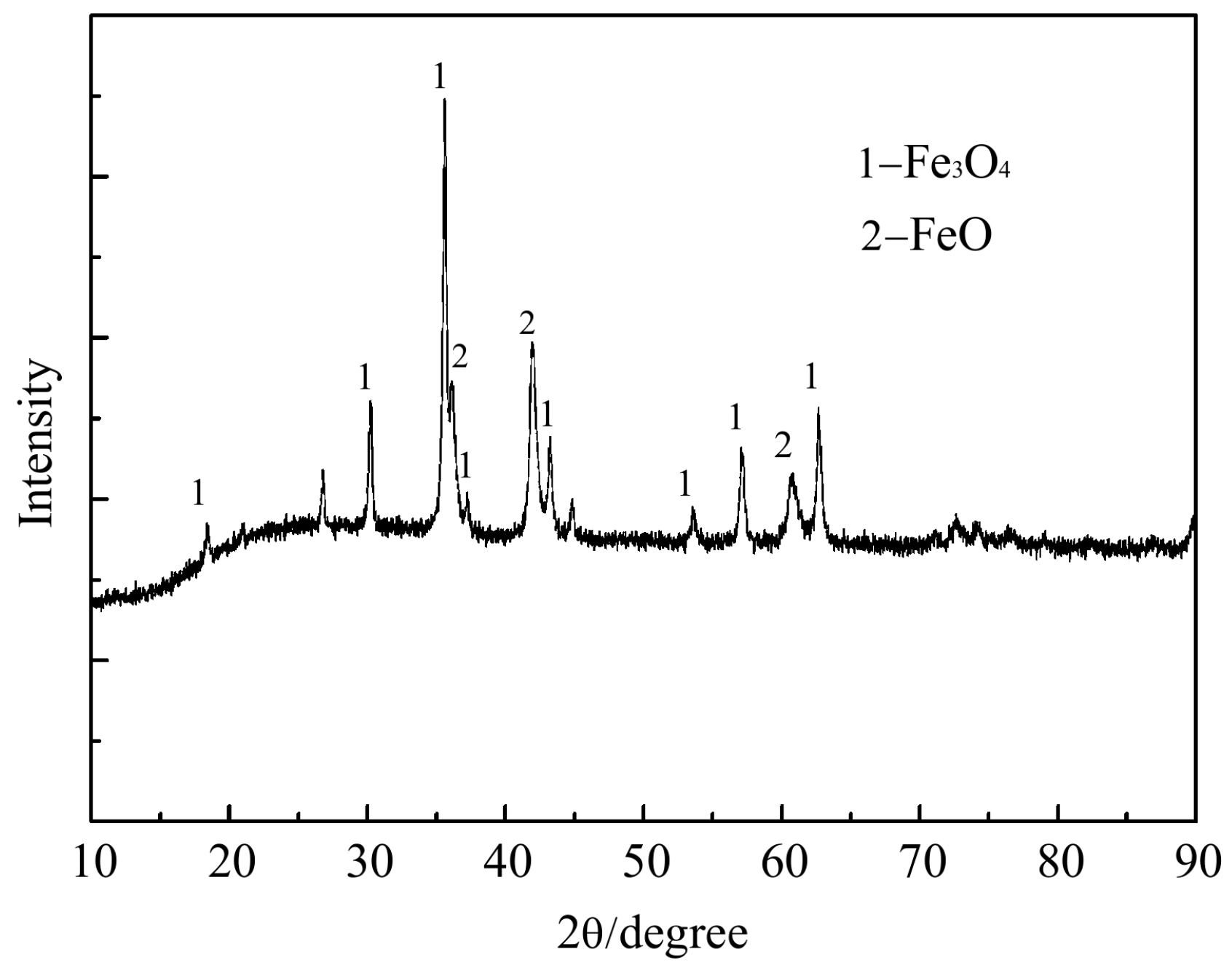
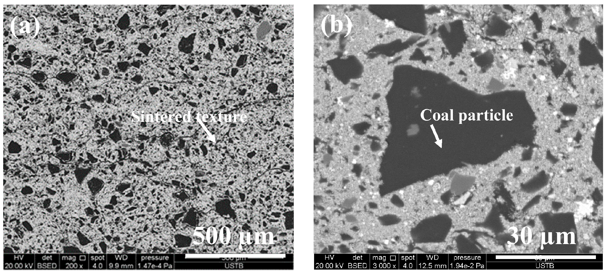
4.1. Characterization of CCB

Figure 3 shows the photo of the prepared CCB. It can be observed that its shape is close to a sphere with d = 0.015 m. Figure 4 presents its XRD pattern, where the major iron-bearing phases are magnetite and wüstite. Figure 5a,b is SEM images of its cross-section. The CCB presented a sintered texture (Figure 5a), and the coal particles were tightly fixed in the bed of the sintered iron-oxide particles (Figure 5b). Chemical analysis showed that the CCB sample had a composition of WC = 20.30 wt.%, WFe2+ = 38.10 wt.%, WFe = 1.57 wt.%, and TFe = 54.00 wt.%. By combining the XRD and chemical analysis results, the mineralogical composition of CCB was calculated and is listed in Table 3.

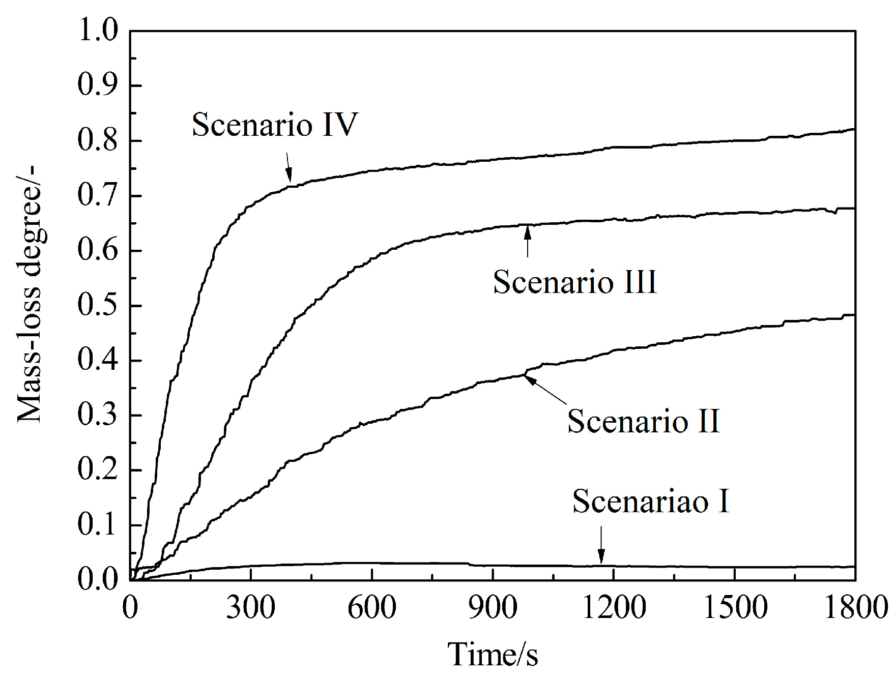
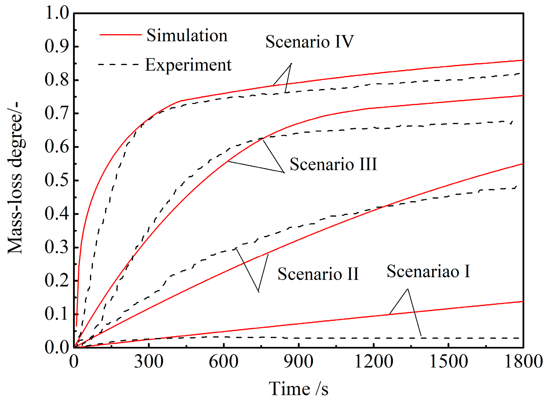
4.2. CCB Model Validation under Simulated BF Conditions

Isothermal reaction tests were conducted under four scenarios and they are listed in Table 4. The four scenarios were designed to simulate the BF in-furnace conditions according to the typical gas composition–temperature profile of the BF [33]. The results are shown in Figure 6. It could be seen that the CCB mass loss was negligible under scenario I, and became observable under scenarios II, III, and IV.
The results of the four scenarios were used for the CCB model validation. In simulating the CCB reaction behavior under each scenario, the environment variables were determined by the experimental conditions. Owing to the sintering of the iron-oxide particles, it was difficult to determine ags in the reaction rates of reactions (1–3). A trial-and-error method was used, and it was found that an effective ags of 1500 m2·m−3 was adequate. The measured and model-predicted mass-loss degree curves under different scenarios were then compared. The results are shown in Figure 7. The model-predicted CCB mass-loss degree at time t was calculated via 1.0 ( 4 π 0 t 0 r ( M O ( R 1 + R 2 + R 3 ) + M C R 4 ) r 2 d r d t ) / ( m C , 0 + m O , 0 ) . From Figure 7, it can be seen that, under each scenario, the model-predicted curve agrees well with the experimental measurement.
The model predicted reduction fraction and carbon conversion of CCB after reacting for 30 min under different scenarios were also compared to the experimental measurements. The results are shown in Table 5. The predicted CCB reduction fraction was calculated using 1.0 ( 4 π 0 r 3.0 ρ Fe 2 O 3 / M Fe 2 O 3 + 4.0 ρ Fe 3 O 4 / M Fe 3 O 4 + 1.0 ρ FeO / M FeO ) r 2 d r ) / ( 1.5 m 0 T Fe / M Fe ) , and the predicted CCB carbon conversion was calculated using 1.0 ( 4 π 0 r ρ C r 2 d r ) / m C , 0 . From Table 5, it can be seen that the agreement between model predictions and experimental measurements is satisfactory.

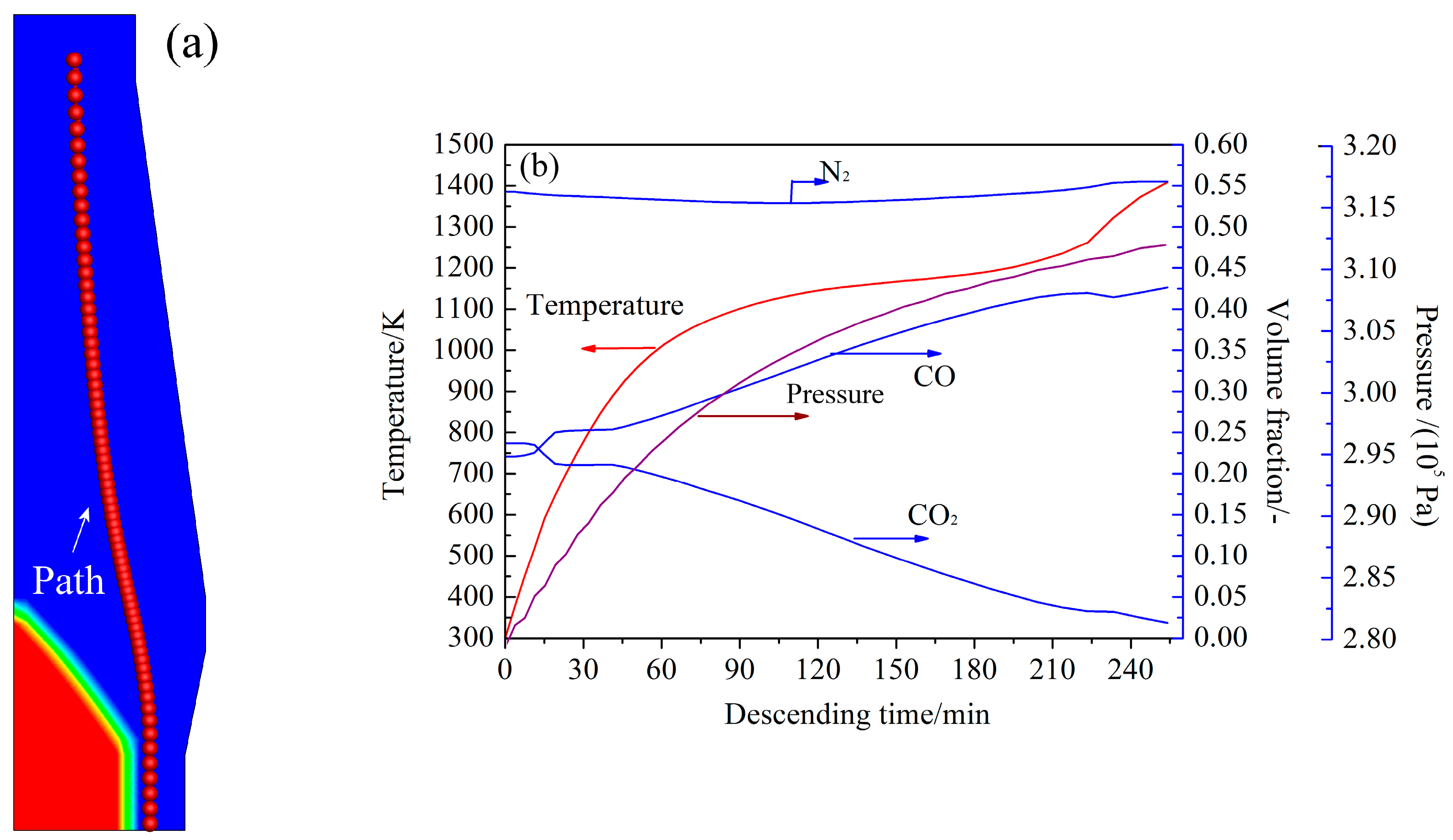
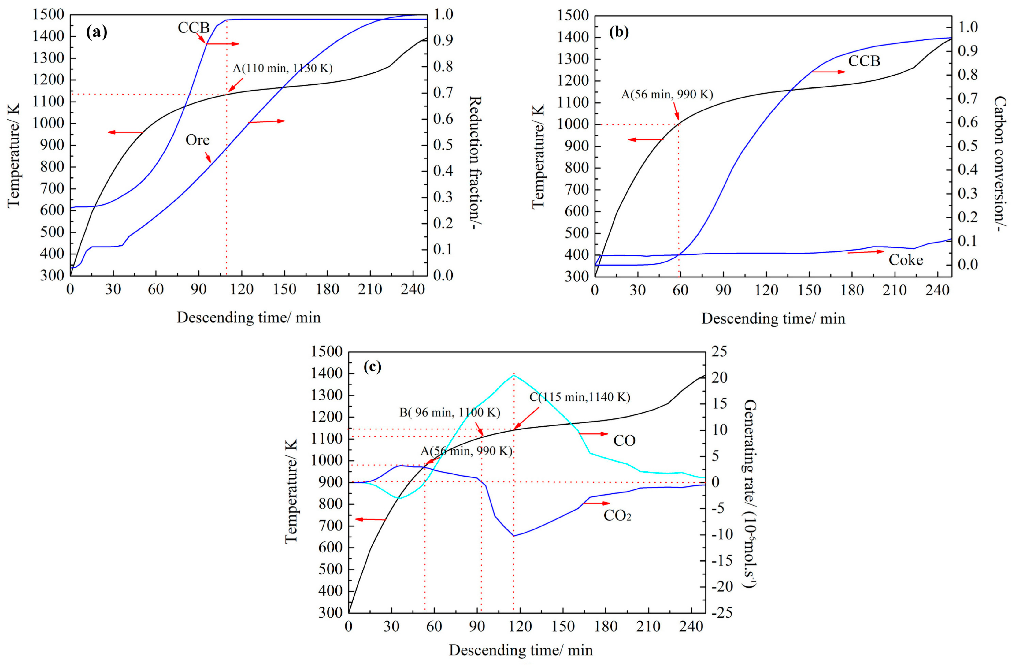
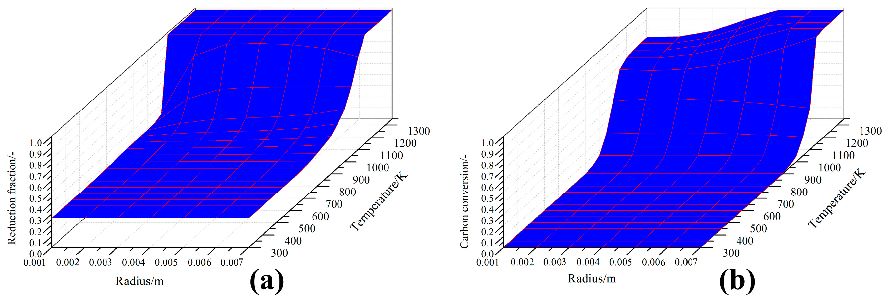
4.3. Simulation of CCB Reaction Behavior in Actual BF

The developed model was applied to predict CCB reaction behavior in an actual BF environment. Some research has indicated that a small addition ratio (e.g., less than 10%) of CCB in the ore burden would not cause considerable changes in a BF. Therefore, a BF environment under normal operation conditions was employed in the present simulations.
The actual BF environment was obtained from the simulation results [34] of a BF of 2500 m3 with a productivity of 6250 ton hot-metal per day. CCB reaction behavior along a burden flowing path near the BF mid-radial zone was investigated (Figure 8a). The scope of the path for investigation was from the burden surface to the upper surface of the cohesive zone (CZ). Along the path, variations of gas pressure, gas composition, and solid temperature with the solid descending time were obtained and have been plotted in Figure 8b. In Figure 8b, the CCB descending time was counted from the burden surface and was calculated using 0 s d s / v S where s is the distance on the path from the burden surface (m) and v S is the burden descending velocity (m/s). Changes of the gas velocity along the path were also needed; however, they were not plotted here for brevity. Thus, in the simulations, at a given time t, the environmental variables were equal to their corresponding BF variables forming the boundary conditions of the model.
Figure 9 shows some simulated results of the CCB reaction behavior along the path. In Figure 9a,b, changes of the reduction fraction of the ore particles and the carbon conversion of coke particles are also plotted. Data of the ore particles and the coke particles are from the BF simulations.
Figure 9a shows the changing reduction behavior of CCB iron oxide. Compared with the ore particles, the reduction of CCB iron oxide proceeded considerably faster; and moreover, the CCB reached full reduction after 110 min (1130 K). Figure 9b shows the gasification behavior of the carbon in the CCB along the path. Compared with the coke particles, the CCB carbon exhibited a considerably higher CO2 reactivity after the temperature reached 990 K (56 min). The CCB carbon conversion was high at 0.90 when the CCB reached the CZ. Figure 9c displays the changes of CCB generation rates of CO and CO2. In Figure 9c, the generation rates of CO and CO2 were calculated via 4 π 0 r ( 2 R 4 R 1 R 2 R 3 ) r 2 d r and 4 π 0 r ( R 1 + R 2 + R 3 R 4 ) r 2 d r , respectively. In the early stage, the CCB produced CO2 and consumed CO from the BF gas. In the period from 56 (990 K) to 96 min (1100 K), it contributed both CO and CO2 to the BF gas. Thereafter, it produced CO and consumed CO2 from the BF gas. After 115 min (1140 K), the CCB reached its maximum rate of carbon gasification.
Combining the results in Figure 9a–c, the CCB reaction behavior along the path was assumed to be the following. Before the CCB temperature reached 990 K, the reactions in the CCB were reactions (1–3). The reduction of the CCB iron oxide was supported by the CO in the BF gas and it proceeded slowly. When the CCB temperature was in the range from 990 to 1130 K, the reactions of CCB were reactions (1–4). The CCB underwent fast self-reduction (e.g., in this stage, both the CCB reduction fraction and CCB carbon conversion presented a fast increase (Figure 9a,b). After the CCB temperature reached 1130 K, the CCB reduction fraction was close to 1.0; however, the gasification of CCB carbon remained active.
The changes of the radial distributions of the local CCB reduction fraction along the path are shown in Figure 10a. Initially, the distribution presented a uniform fashion; however, after the temperature reached 1000 K, the distribution became uneven. The iron oxides near the CCB surface were reduced considerably faster than those near the CCB center. However, when the temperature was more than 1150 K, the distribution returned to a uniform state. The changes of the radial distributions of the local CCB carbon conversion along the path are shown in Figure 10b. Initially, the distribution was uniform; however, after the temperature reached 1000 K, the uniform distribution was destroyed. The gasification of carbon particles near the surface occurred faster than those near the center. At 1150 K, the local carbon conversion reached 1.0 near the surface and approximately 0.7 near the center. Subsequently, the uneven distribution showed marginal change with any further increase of the temperature. The above finding indicates that reactions in the CCB proceeded in an uneven fashion along the path and this phenomenon was evident in the CCB self-reducing stage.

5. Conclusions

To investigate the CCB reaction behavior in BF, in this study, a combined experimental and numerical investigation was carried out. The CCB samples were prepared by cold briquetting and heat treatment. The prepared CCB had a composition of 20.10 wt.% carbon, 29.70 wt.% magnetite, 39.70 wt.% wüstite, and 1.57 wt.% metallic iron. Its reaction kinetics under the simulated BF conditions was investigated and modeled. Based on the experimental findings, its reaction behavior along the mid-radial flowing path in a BF of 2500 m3 was examined by numerical simulations.
The CCB reaction kinetics under BF atmosphere could be modeled on the basis of the conservation of gas and solid species inside the CCB, and the mass transfer between the CCB and the environment. The model predictions agreed well with the experimental measurements. Therefore, the developed CCB model was reliable.
The simulation results showed that, along the mid-radial flowing path in the BF, before the temperature reached 990 K, the CCB was reduced by CO in the BF gas. When the temperature was in the range from 990 to 1130 K, it underwent self-reducing and contributed both CO and CO2 to the BF gas. When the temperature was above 1130 K, the CCB showed a full reduction of iron oxide and active carbon gasification. Moreover, the results also revealed that, along the path, the reduction of iron oxide and the gasification of carbon proceeded unevenly inside the CCB. The uneven radial distributions of the local parameters were evident in the CCB self-reducing stage.
Considering different descending paths, the developed model could be applied for designing and optimizing the CCB charge operation in BF.

Author Contributions

H.T. conceived and designed the experiments; Y.S. performed the experiments and the simulations; Y.S. and T.R. analyzed the data; H.T. wrote the paper. All authors have read and agreed to the published version of the manuscript.

Funding

This research was funded by the National Natural Science Foundation of China grant number [U1960205].

Acknowledgments

The authors thank the National Natural Science Foundation of China (No. U1960205) and the State Key Laboratory of Advanced Metallurgy USTB for the financial support for this work.

Conflicts of Interest

The authors declare no conflicts of interest.

Abbreviations

Table of Symbols
agsgas–ore interface area, (m2·m−3)
dCCB diameter, 0.015 (m)
DCO-N2,DCO2-N2, Deffgas diffusivity, effective gas diffusivity, (m2·s−1)
fireaction fraction, (-)
kireaction rate constant of Reaction i, (m·s−1, s−1·atm−1)
Kiequilibrium constant of Reaction i, (-)
Mmolar weight, (kg·mol−1)
mmass, (kg)
Ppressure, (Pa)
rradial direction, (m)
ReReynolds number, (-)
Rconstant, 8.314 (J·mol-1·K-1)
Richemical reaction rate of Reaction i, (mol·m−3⋅s−1)
ScSchemit number, (-)
Ttemperature, (K)
ttime, (s)
uvelocity, (m·s−1)
µviscosity, (kg·m−1·s−1)
αporosity, (-)
ρdensity, (kg·m−3)
Subscripts
0initial
ggas
eenvironment
Species or element namevariable of assigned species or element

References

  1. Geerdes, M.; Chaigneau, R.; Kurunov, I. Modern Blast Furnace Ironmaking: An Introduction; IOS Press: Amsterdam, The Netherlands, 2015; pp. 10–12. ISBN 978-1-61499-498-5. [Google Scholar]
  2. Song, J.; Jiang, Z.; Bao, C.; Xu, A. Comparison of energy consumption and CO2 emission for three steel production routes—Integrated steel plant equipped with blast furnace, oxygen blast furnace or COREX. Metals 2019, 9, 364. [Google Scholar] [CrossRef] [Green Version]
  3. Tan, X.; Li, H.; Guo, J.; Gu, B.; Zeng, Y. Energy-saving and emission-reduction technology selection and CO2 emission reduction potential of China’s iron and steel industry under energy substitution policy. J. Clean. Prod. 2019, 222, 823–834. [Google Scholar] [CrossRef]
  4. Ahmed, H.M.; Viswanathan, N.; Bjorkman, B. Composite pellets–a potential raw material for iron-making. Steel Res. Int. 2014, 85, 293–306. [Google Scholar] [CrossRef]
  5. Kasai, A.; Toyota, H.; Nozawa, K.; Kitayama, S. Reduction of reducing agent rate in blast furnace operation by carbon composite iron ore hot briquette. ISIJ Int. 2011, 51, 1333–1335. [Google Scholar] [CrossRef] [Green Version]
  6. Zhao, W.; Chu, M.S.; Wang, H.T.; Liu, Z.G.; Tang, Y.T. Novel blast furnace operation process involving charging with low-titanium vanadium–titanium magnetite carbon composite hot briquette. Int. J. Miner. Metall. Mater. 2016, 23, 501–510. [Google Scholar] [CrossRef]
  7. El-Hussiny, N.A.; Shalabi, M.E.H. A self-reduced intermediate product from iron and steel plants waste materials using a briquetting process. Powder Technol. 2011, 205, 217–223. [Google Scholar] [CrossRef]
  8. Flores, B.D.; Guerrero, A.; Flores, I.V.; Borrego, A.G.; Díez, M.A.; Osório, E.; Vilela, A.C.F. On the reduction behavior, structural and mechanical features of iron ore-carbon briquettes. Fuel Process. Technol. 2017, 155, 238–245. [Google Scholar] [CrossRef]
  9. Watanabe, K.; Ueda, S.; Inoue, R.; Ariyama, T. Enhancement of reactivity of carbon iron ore composite using redox reaction of iron oxide powder. ISIJ Int. 2010, 50, 524–530. [Google Scholar] [CrossRef] [Green Version]
  10. Kasai, A.; Matsui, Y. Lowering of thermal reserve zone temperature in blast furnace by adjoining carbonaceous material and iron ore. ISIJ Int. 2004, 44, 2073–2078. [Google Scholar] [CrossRef]
  11. Singh, M.; Björkman, B. Testing of cement-bonded briquettes under laboratory and blast furnace conditions Part 1–Effect of processing parameters. Ironmak. Steelmak. 2007, 34, 30–40. [Google Scholar] [CrossRef]
  12. Kowitwarangkul, P.; Babich, A.; Senk, D. Reduction behavior of self-reducing pellet (SRP) for low height blast furnace. Steel Res. Int. 2014, 85, 1501–1509. [Google Scholar] [CrossRef]
  13. Chu, M.; Liu, Z.; Wang, Z.; Yagi, J.I. Fundamental study on carbon composite iron ore hot briquette used as blast furnace burden. Steel Res. Int. 2011, 82, 521–528. [Google Scholar] [CrossRef]
  14. Matsui, Y.; Sawayama, M.; Kasai, A.; Yamagata, Y.; Noma, F. Reduction behavior of carbon composite iron ore hot briquette in shaft furnace and scope on blast furnace performance reinforcement. ISIJ Int. 2003, 43, 1904–1912. [Google Scholar] [CrossRef]
  15. Tang, H.; Liu, S.; Rong, T. Preparation of high-carbon metallic briquette for blast furnace application. ISIJ Int. 2019, 59, 22–30. [Google Scholar] [CrossRef] [Green Version]
  16. Narita, C.Y.B.; Mourao, M.; Takano, C. Development of composite briquettes of iron ore and coal hardened by heat treatment. Ironmak. Steelmak. 2015, 42, 548–552. [Google Scholar] [CrossRef]
  17. Yokoyama, H.; Higuchi, K.; Ito, T.; Oshio, A. Decrease in carbon consumption of a commercial blast furnace by using carbon composite iron ore. ISIJ Int. 2012, 52, 2000–2006. [Google Scholar] [CrossRef] [Green Version]
  18. Kemppainen, A.; Iljana, M.; Heikkinen, E.P.; Paananen, T.; Mattila, O.; Fabritius, T. Reduction behavior of cold-bonded briquettes under simulated blast furnace conditions. ISIJ Int. 2014, 54, 1539–1545. [Google Scholar] [CrossRef] [Green Version]
  19. Mochizuki, Y.; Tsubouchi, N.; Akiyama, T. Investigation of strength and reduction reactivity during heat treatment in simulated-experimental blast furnace of carbon-containing pellet prepared by vapor deposition of tar to cold-bonded pellet with large particle size. Fuel Process. Technol. 2018, 176, 21–32. [Google Scholar] [CrossRef]
  20. Man, Y.; Feng, J.X.; Li, F.J.; Ge, Q.; Chen, Y.M.; Zhou, J.Z. Influence of temperature and time on reduction behavior in iron ore–coal composite pellets. Powder Technol. 2014, 256, 361–366. [Google Scholar] [CrossRef]
  21. Liu, C.; Ding, X.; Dai, J.; Tang, Z.; Dong, Y. Comprehensive CFD modeling of reduction behavior inside coal-based composite pellets. Ironmak. Steelmak. 2019, 1–10. [Google Scholar] [CrossRef]
  22. Sun, K.; Lu, W.K. Mathematical modeling of the kinetics of carbothermic reduction of iron oxides in ore-coal composite pellets. Metall. Mater. Trans. B 2009, 40, 91–103. [Google Scholar] [CrossRef]
  23. Shi, J.; Donskoi, E.; McElwain, D.L.S.; Wibberley, L.J. Modelling the reduction of an iron ore-coal composite pellet with conduction and convection in an axisymmetric temperature field. Math. Comput. Model. 2005, 42, 45–60. [Google Scholar] [CrossRef]
  24. Donskoi, E.; McElwain, D.L.S. Mathematical modeling of no-isothermal reduction in highly swelling iron ore-coal char composite pellet. Ironmak. Steelmak. 2001, 28, 384–389. [Google Scholar] [CrossRef]
  25. Tang, H.; Yun, Z.; Fu, X.; Du, S. Modeling and experimental study of ore-carbon briquette reduction under CO–CO2 atmosphere. Metals 2018, 8, 205. [Google Scholar] [CrossRef] [Green Version]
  26. Chu, M.; Nogami, H.; Yagi, J.I. Numerical analysis on charging carbon composite agglomerates into blast furnace. ISIJ Int. 2004, 44, 510–517. [Google Scholar] [CrossRef]
  27. Ueda, S.; Yanagiya, K.; Watanabe, K.; Murakami, T.; Inoue, R.; Ariyama, T. Reaction model and reduction behavior of carbon iron ore composite in blast furnace. ISIJ Int. 2009, 49, 827–836. [Google Scholar] [CrossRef] [Green Version]
  28. Tien, R.H.; Turkdogan, E.T. Gaseous reduction of iron oxides: Part IV. Mathematical analysis of partial internal reduction-diffusion control. Metall. Trans. 1972, 3, 2039–2048. [Google Scholar] [CrossRef]
  29. Natsui, S.; Kikuchi, T.; Suzuki, R.O. Numerical analysis of carbon monoxide–hydrogen gas reduction of iron ore in a packed bed by an Euler–Lagrange approach. Metall. Mater. Trans. B 2014, 45, 2395–2413. [Google Scholar] [CrossRef]
  30. Leffler, A.J. Determination of effective diffusivities of catalysts by gas chromatography. J. Catal. 1966, 5, 22–26. [Google Scholar] [CrossRef]
  31. Ge, Q. Kinetics of Gas-Solid Reactions, 1st ed.; Nuclear Energy Press: Beijing, China, 1991; pp. 9–12. ISBN 7502204008. [Google Scholar]
  32. Guo, K.L.; Kong, X.; Chen, S. Numerical Heat Transfer, 1st ed.; China Science & Technology University Press: Hefei, China, 1988; pp. 42–48. ISBN 7-312-00038. [Google Scholar]
  33. Turkdogan, E.T. Blast furnace reactions. Metall. Mater. Trans. B 1978, 9, 163–179. [Google Scholar] [CrossRef]
  34. Tang, H.; Rong, T.; Fan, K. Numerical investigation of applying high-carbon metallic briquette in blast furnace ironmaking. ISIJ Int. 2019, 59, 810–819. [Google Scholar] [CrossRef] [Green Version]
Figure 1. Schematic diagram of the experimental setup.
Metals 10 00049 g001
Figure 2. Concept of the CCB reaction model in the BF environment.
Metals 10 00049 g002
Figure 3. Photo of the CCB.
Metals 10 00049 g003
Figure 4. XRD pattern of the CCB sample.
Metals 10 00049 g004
Figure 5. SEM images of the CCB sample: (a) ×200 (b) ×3000.
Metals 10 00049 g005
Figure 6. Variation of mass-loss degree with time under different scenarios.
Metals 10 00049 g006
Figure 7. Comparison of the mass-loss degree curves between the model predictions and the experiments.
Metals 10 00049 g007
Figure 8. (a) Illustration of the CCB flowing path in the BF. (b) Change of the BF variables along the flowing path.
Metals 10 00049 g008
Figure 9. Changes of the CCB reduction fraction (a), CCB carbon conversion (b), and CCB generation rate of CO and of CO2 (c) along the flowing path.
Metals 10 00049 g009
Figure 10. Radial distributions of the local reduction fraction (a) and local carbon conversion (b) under different CCB temperatures.
Metals 10 00049 g010
Table 1. Properties of the coal fines.
Proximate Analysis (* ad, wt.%)Element Analysis (* daf, wt.%)Ash Analysis (wt.%)
Volatile* FCAshMoistureCHONSSiO2Al2O3CaOFe2O3Other
17.8771.719.251.1789.443.065.921.180.4046.735.07.594.81.54
* ad: Air-dried; daf: Dry and ash-free; FC: Fixed carbon.
Table 2. Reactions involved in the model.
No.ReactionReaction Rate (mol·m−3·s)Ref.
1 3   Fe 2 O 3 ( s ) + CO ( g ) = 2   Fe 3 O 4 ( s ) + CO 2 ( g ) R i = ( P CO P CO 2 / K i ) / ( 8.314 T ) ( K i / ( k i ( 1 + K i ) ) ( 1 f i ) 2 / 3 ) a gs (i = 1,2,3),
k 1 = exp ( 1.445 6038 / T ) , K 1 = exp ( 7.255   +   3720 / T )
k 2 = 1.70 exp ( 2.515 4811 / T ) , K 2 = exp ( 5.289 4711 / T ) ,
k 3 = exp ( 0.805 7385 / T ) , K 3 = exp ( 2.946 + 2744.63 / T )
[27,28,29]
2 Fe 3 O 4 ( s ) + CO ( g ) = 3   FeO ( s )   +   CO 2 ( g )
3 FeO ( s ) + CO ( g ) = Fe ( s )   +   CO 2 ( g )
4 C ( s ) + CO 2 ( g ) = 2   CO ( g ) r 4 = ρ C , 0 k 4 ( 1 f 4 ) 2 / 3 ( P CO 2 / 1.01 × 10 5 ) / M C ,   k 4 = 1800 exp ( 138000 / R T ) [15,25]
Table 3. CCB mineralogical composition (wt.%).
CarbonMagnetiteWüstiteMetallic IronGangue
20.3029.7039.701.578.73
Table 4. Scenarios for the isothermal CCB reaction tests (30 min).
ScenarioTemperature (K)CO2 (vol.%)CO (vol.%)N2 (vol.%)
I1073203050
II1173153550
III1273104050
IV1373104050
Table 5. Measured and model-predicted parameters of CCB after reacting for 30 min.
ItemReduction FractionCarbon Conversion
Scenario IIIIIIVIIIIIIIIV
Measured0.300.530.840.900.050.180.530.65
Model-predicted0.390.880.980.980.100.300.560.70

