Article

Carbon Impact Mitigation of the Iron Ore Direct Reduction Process through Computer-Aided Optimization and Design Changes

Institut Jean Lamour, CNRS, Université de Lorraine, Labex DAMAS, 54011 Nancy, France
*
Author to whom correspondence should be addressed.
Metals 2020, 10(3), 367; https://doi.org/10.3390/met10030367
Submission received: 11 February 2020 / Revised: 3 March 2020 / Accepted: 10 March 2020 / Published: 12 March 2020
(This article belongs to the Special Issue Mathematical Modeling and Simulation in Ironmaking and Steelmaking)

Abstract

:
The steel industry is known to have one of the highest environmental impacts on the industrial sector, especially in terms of CO2 emissions. The so-called direct reduction route, which makes use of reformed natural gas along with top gas recycling to reduce iron oxide pellets with H2 and CO, is responsible for lower CO2 emissions than the classic blast furnace route and is currently under development. The present article focuses on the direct reduction process and discusses means to further decrease the CO2 emission rate. A set of 10 operating parameters were simultaneously changed according to computer-aided optimization. The results provide about 15% improvement over original emissions for comparable output values.

1. Introduction

World steel production accounts for 4–6% of global CO2 emissions [1,2]. This can be related to the widely adopted use of the blast furnace for the chemical reduction of iron ore [3]. Efforts have thus been put forth to tackle these emissions as indicated in [4] and [5], which stressed the importance of alternative technologies. One promising and developing process is the so-called Direct Reduction (DR) process, and its primary technique MIDREX (Midland-Ross Direct Iron Reduction) [6]. This technology has seen increased interest, namely in cases with high natural gas reserves [7,8].
The MIDREX-type DR process operating principle is highlighted in Figure 1. Natural gas (1) is heated and transformed in the reformer (2) into reducing gas (3), which is sent to a shaft furnace where iron oxide pellets (I) are reduced into Direct Reduced Iron (DRI) (II) while the gas is oxidized and exits as top gas (4). This gas is scrubbed and split into a section sent to the reformer (5) and another one sent to the burner (6), which then provides the heat for reforming and other applications.
The reducing gas is a mixture of CO, H2, CO2, H2O, CH4 and N2, with the first components having the highest proportion. Top gas on the other hand has CO2 and H2O in a higher proportion with the presence nonetheless of other components.
CO2 is emitted along with other gases in the flue gas (7), which is the only gas exiting the system. Carbon emissions m C , f l u e   g a s   ( kg   h 1 ) are usually normalized to the amount of DRI leaving the system m D R I   ( kg   h 1 ) as indicated in Equation (1).
C n o r m ( kg kg ) = m C , f l u e   g a s m D R I
The shaft furnace of the DR process was investigated and modeled in several research works, a recent review of which is given in [9]. These shaft furnaces models differ according to the geometrical description of the shaft (1D, 2D, 3D, with the reduction zone alone, or with the transition and cooling zones), the description of the gas and solid flow, the thermal transfers accounted for, and, above all, the number of chemical reactions considered. Common results regarding the thermal behavior are as follows. Temperatures of solid and gas are in equilibrium in the main part of the shaft, those temperatures being almost constant in the reducing zone. Methane reforming and Boudouard reactions have an important impact on the temperature inside the shaft. A noticeable finding from 2D, 3 zones, Computational Fluid Dynamics (CFD)-type models is the evidence that a fraction of the cooling gas goes up to the transition and reduction zones and negatively impacts the DRI metallization (incomplete reduction) [10,11]. This gas, however, has a positive impact on the carbon deposition.
Interesting sensitivity analyses can be, and were, made using such models. Parisi and Laborde investigated the production vs. metallization dilemma and indicated that metallization decreases with production and vice-versa [12]. They also highlighted a 7% production increase when increasing the CO rate in a constant (CO + H2) flow rate (thus reducing H2 flow rate correspondingly). This was attributed to CO being a better reducer than H2. Moreover, the authors stressed the importance of studying the coupling between the shaft reactor and the reformer for the identification of feasible optimal results. Alamsari et al. studied the impact of higher input gas temperature. It was concluded that this condition led to higher cooling gas requirements and ultimately to higher carbon contents in exiting DRI [13]. Nouri et al. [14] found that a higher gas flow rate led to higher solid conversion, and linked it to higher reducing gas concentration near the solid inlet. Moreover, these authors underlined the need for a smaller H2/CO ratio for higher iron production rates, as well as the importance of having a higher reducing power ( CO + H 2 ) / ( CO 2 + H 2 O ) ratio for higher solid conversion. A lower limit of 1 and an upper limit of 20 were identified for the two ratios, namely with the concern of reformer operation. These authors further studied the effect of solid flow rate, reactor length and pellet size. It was found that a lower solid flow rate, a higher reactor length and a smaller pellet size all positively affected solid conversion rate, with the inverse being true. Shams et al. modelled the shaft reactor in its entirety (reduction, transition and cooling zones) [15]. They investigated the effect of increasing the cooling gas flow rate on the output solid temperature and carbon deposition. The authors found an optimum and economical value beyond which only a little more solid cooling was observed. They related the increase in solid carbon formation to the increase in the cooling gas input. None of these works modeled or studied the interaction between the shaft reactor and the reformer.
Ajbar et al. studied the process changes in light of this interaction [16]. The authors thus investigated the effect of recycling ratio, scrubber exit temperature and flow rates of oxygen and natural gas at different point of the process. Results indicated the presence of an optimum for metallization and carbon content with regards to natural gas input before and after the reformer. An optimum also existed for metallization with regards to the recycling ratio, which decreased the carbon content in output DRI. Increase in plant capacity and in scrubber output temperature led to reduced performance whereas increase in oxygen input and natural gas sent to cooling and transition zones improved performance. Ghadi et al. studied the effect of injecting the reducing gas at different heights in the reactor and found that this change increases the overall reduction degree, or reduces H2 consumption for a fixed reduction degree [17]. Hamadeh explored the impact of furnace radius, area of gas injection port, cooling and reducing gas flow rates, reducing gas composition, and pellet diameter [18]. It was deduced that the metallization decreased with greater reactor radius, greater solid gas flow rate and temperature. This metallization increased with reduced cooling gas temperature as well as a smaller H2/CO ratio. He also attempted to model the reformer and couple it with the shaft furnace; no coupled optimization work was, however, performed. Although those works provide ample information on the influence of process parameters, they do not address the important aspect of carbon emission reduction.
The CO2 issue was addressed by Duarte and Becerra in [19], where carbon emissions were reduced by 10% via the use of an acid gas absorption system for CO2 removal from the recycled top gas, added to the inclusion of in-situ CH4 reforming. However, no modification to process operating parameters was realized. Tanaka also proposed the use of in-process heat integration as well as the foregoing of the cooling zone for hot DRI production [20]. Knop and Ångström patented the use of a water gas shift reactor in place of the scrubber and natural gas reformer, with a subsequent CO2 removal system, leading to a pure H2 reducing gas [21]. This, however, represents a drastic change over the initial MIDREX process. Using a systems model of the process, which couples the DR shaft with the process gas loop, Bechara et al. investigated the modification of operating parameters, namely H2, CO, CO2 and H2O flow rates [9]. By trial-and-error, optimal values were found that respected the trade-off between minimal normalized carbon emissions and feasible process designs.
This present work is a continuation of this last work and seeks to employ computer-aided optimization and design to further lower the score of the DR process regarding CO2 emissions.

2. Modeling Scheme

The Midrex process was modeled in its entirety using the commercial software Aspen Plus V8 (AspenTech, Boston, MA, USA) and Figure 2 schematically illustrates the main components of the process flow diagram we built, with emphasis on the gas loop. Our model includes the shaft furnace and the reformer, which are physically connected through the gas loop. With this connection, any change in the reformer operating parameter automatically translates into a feedback in the shaft furnace, and the reciprocal is also true. Main physico-chemical reactions and corresponding heat streams are handled in this model, which ensure mass and energy balances.
The shaft furnace is the heart of the DR process. Therein, descending iron ore pellets are reduced and cooled yielding the cold DRI product. The reducing gas enters the shaft furnace at an intermediate position, ascends in the furnace and realizes the iron ore reduction before exiting at the top of the furnace. A cold gas, usually natural gas, is injected at the bottom of the furnace to cool down the exiting reduced iron pellets.
The shaft furnace is a complex reactor, which can be divided into identified zones exhibiting different temperatures and where multiple chemical reactions, cited in Table 1, take place. Such a reactor cannot be handled with the standard reactors’ library offered by Aspen Plus and a complete FORTRAN program was written in a custom block to model the shaft furnace. This Aspen Plus shaft furnace model is derived from previous works of our group [11,22] and was presented in detail in [9]; its main features are recalled below.
Based on the physical divisions of the shaft furnace mentioned in [11], the reactor modeled in Aspen Plus was split into four different zones as highlighted in Figure 3. Zone 1 and Zone 2 correspond to the reduction zone. Zone 1 is the widest peripheral zone with the reduction gas and the majority of the pellets as inputs; this zone leads to complete metallization of the iron oxides. Zone 2 is smaller and occupies a central position, with a small fraction of the pellets and gas from the transition zone as inputs; this zone leads to incomplete metallization of the iron oxides. The third zone is the Transition zone, which has a fraction of the hot cooling gas and the descending hot reduced pellets as inputs. When natural gas is used as a cooling agent, carbon deposition is the most important reaction in this zone. The fourth and final zone is the cooling zone. It has cooling gas and hot carbonized metallized iron as inputs, with cold DRI and a fraction of the cooling gas as outputs. The cooling zone was modeled as a simple heat exchanger, whereas Zone1, Zone2 and Transition Zone, were modeled using a 1D version of the finite volume model of [11], with a specific pellet sub-model using the concept of the additive characteristic times for the reduction kinetics and convection-diffusion for heat exchanges. The model was then solved iteratively until the difference in previous and actual values for temperatures and compositions for each element was within an acceptable range.
The gas loop operations were modeled using standard blocks from the Aspen Plus library, namely ‘Gibbs’ and ‘stoichiometric’ reactors, flash condenser and heat exchangers. Several design specifications were introduced into the model to fix realistic objectives for various parameters, such as top gas recycling ratio or gases input flow rates and help global convergence. The important point to note here is that the whole plant model operates according to the following procedure:
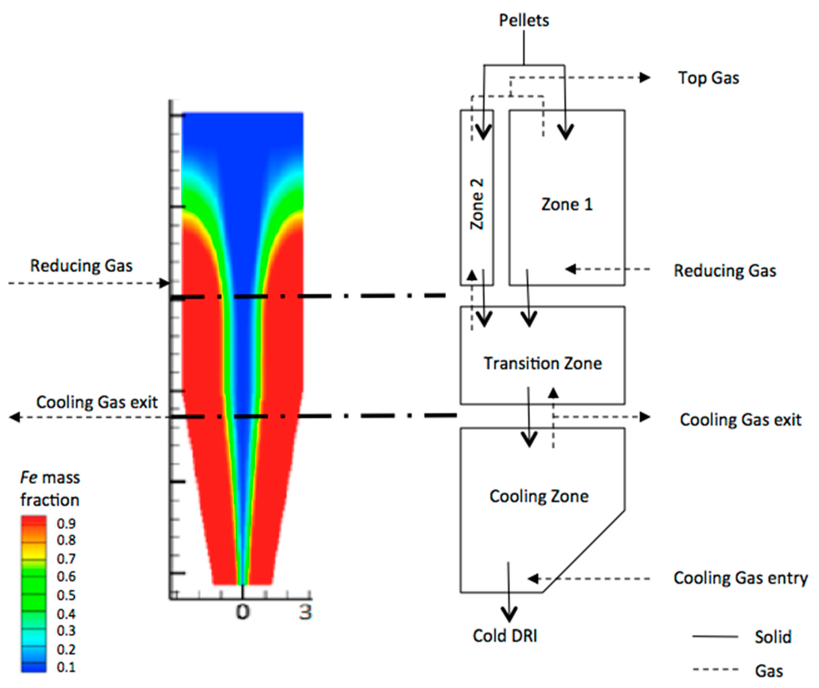
  • The reducing gas characteristics (composition, temperature), pellet properties (diameter, flow rate) and the reactor dimensions are considered as model inputs, with the cooling gas specified.
  • The split of input pellets between Zone 1 and Zone 2 s p l F e is calculated based on the given reducing and cooling gas flow rates.
  • The shaft outputs are calculated and the DRI as well as top gas properties are determined.
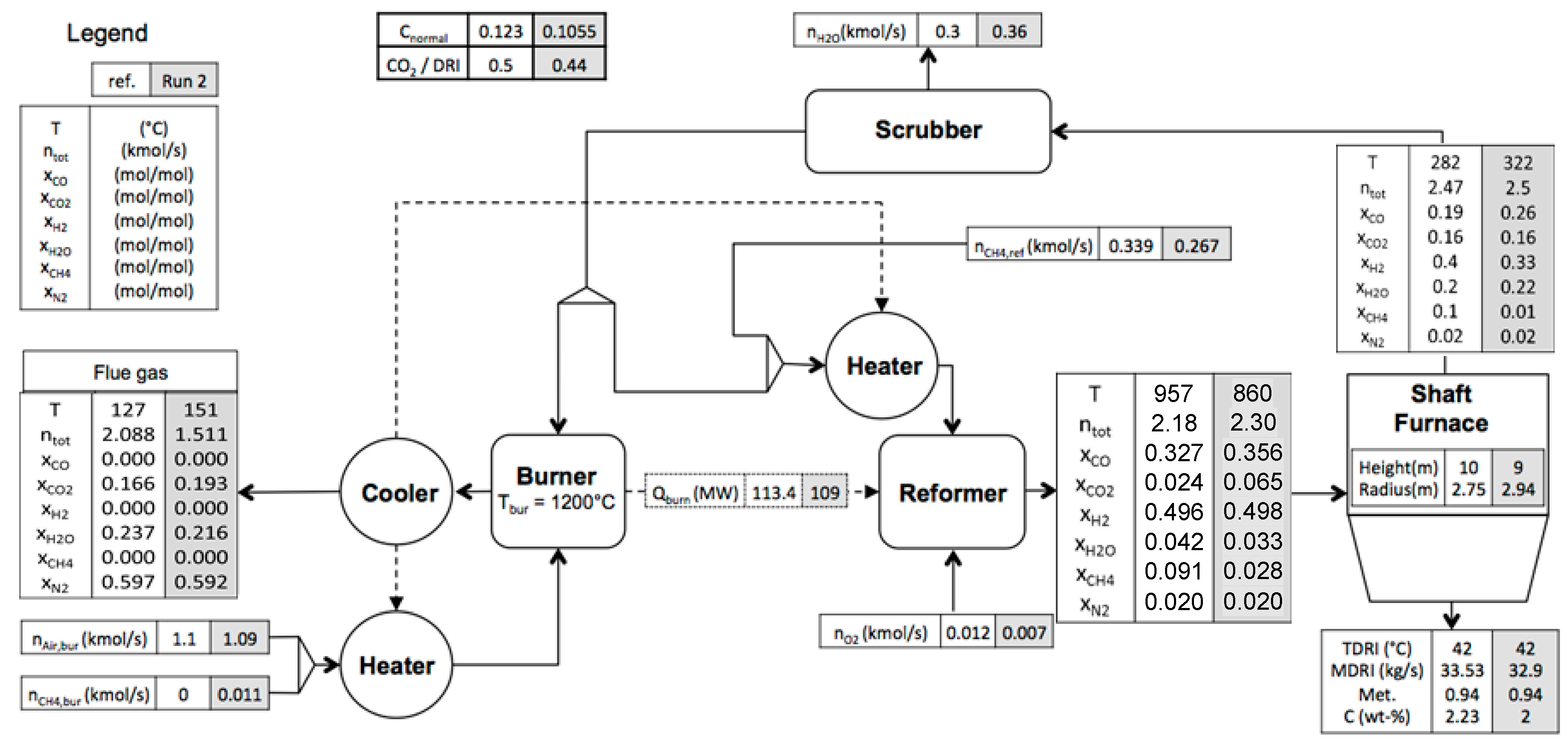
  • The gas loop is calculated with top gas as input with the goal of having a converged recycling. The convergence is obtained when the calculated heated outlet reformed gas characteristics are sufficiently close to the inlet reducing gas characteristics.
The whole model was described in detail, as well as its validation against industrial data, in a previous article [9]. We recall here that the validation step was conducted against data of the Contrecœur plant, Canada, which produces 120 t/h of cold DRI for an input of 20 t/h of natural gas. The calculated metallization was equal to 93.9% against 93.8% for the factory. Carbon content was equal to 2.3% against 2.0% in the real case. Finally, overall error did not exceed 6%. The same plant is taken as a base case in the present paper.

3. Process Computer-Aided Optimization

As an improved alternative to traditional sensitivity analyses and simple optimizations by trail-and-error, we retained here the approach of computer-aided multi-variable process optimization, which generates fast and automated propositions of optimal solutions. The optimization was directly conducted via the optimization features offered in Aspen Plus.

3.1. Definition of the Optimization Problem

The first step of the optimization process was the choice of the objective function, defined in Equation (2) (optimality) and which contained the following:
  • The first term is the normalized carbon emissions that need to be minimized. This term was multiplied by a power (a = 0.5) of the relative wustite reduction height h FeO h r e a c . hreac is the reactor height and hFeO is the height where wustite rate falls below a low value (10−6 kg h−1). This was done in order to keep a good column performance.
  • Two other terms were added to ensure the feasibility of the proposed modifications. The middle term drives the convergence of the gas loop (feasibility), ensured when the H2 flowrate at the reformer outlet is equal to that at the shaft inlet: n H 2 , r e f n H 2 , r e d u c i n g   g a s 0 . The last term was added to get similar metallization rates, via the input pellet split between original and optimized cases: s p l p e l l e t s , 0 s p l p e l l e t s 0 .
    o b j = C n o r m a l × ( h FeO h r e a c ) a + 10 × | n H 2 , r e f n H 2 , r e d u c i n g   g a s | + 10 × | s p l p e l l e t s , 0 s p l p e l l e t s |
With this in mind, the optimal function will provide minimal normalized carbon emissions for a good column performance along with a converged gas loop and an acceptable metallization degree.
The next step consisted of choosing the optimization variables and their corresponding ranges, which are both reported in Table 2. The ranges were chosen to orbit around the original nominal industrial values of the selected plant.
Regarding the optimization algorithm, the choice was made on the Aspen Plus built-in Complex algorithm. This algorithm, based on the constraint Simplex Nelder-Mead method, does not require any derivative information. This rendered it suitable for this problem, which involves rigorous calculations with non-smooth functions. In addition, it is suited to cases with bounds on handled variables as well as a recycling loop, as in the present case [23]. This method found extensive application in engineering. Recent examples were Diesel engine optimization [24], membrane fuel cell [25] and manufacturing systems [26]. Its principle is as follows [27,28].
The constrained Simplex (Complex) method searches for the maximum value of a function whose variables are bounded between an upper and a lower constraint. It starts from an initial point respecting all the constraints. This point is represented in this context by the reference case. A series of random points is next generated and evaluated. The algorithm then employs a geometric-based search method by replacing the worst point by a new one obtained by reflecting the worst through the centroid of the remaining points in the complex. The procedure of moving the worst point towards the centroid is repeated until the new points stop repeating as the worst, whilst the algorithm exits when the Complex has converged or until a maximum number of evaluations is reached.

3.2. Launching of Optimization Runs

Two runs were launched with different choices of optimization variables. For the first run, only gas related variables were used for optimization. The second run considered gas related variables, pellet size and mass flow rate and some structural parameters in addition: radius and height of the shaft reactor.
Results obtained after convergence of the Complex optimization method are reported in Table 3 and are presented in terms of flowsheet for reference case and run 2 in Figure 4.

3.3. Results Analysis

A first look at the results shows that, as expected, the two optimization runs provide better normalized carbon ratio than the reference case. Surprisingly the same value of 0.105 is obtained for the two runs with very different operating conditions, run 1 allowing variations in the gas properties only, while run 2 allowed variations in the pellet size and flowrate, and in the shaft reactor geometry in addition to gas properties.
The degree of metallization is quite similar in the three cases and the fraction of carbon in the DRI as well, even though this value is slightly lower than the reference case (15% less) for the second run. Production of DRI is also similar in the three cases despite the free pellet flow rate allowed in run 2.
One important result of those simulations lies in the temperature of the reducing gas, which is significantly lower in the optimizations runs than in the reference case. Run 1 exhibits a temperature of 882 °C and run 2 of 860 °C, while reference case is at 957 °C. Those differences are great and can be easily explained. Indeed, the higher the temperature, the higher the energy needs; more energy means more gas sent to the burner and ultimately more CO2 released in the flue gas. As our optimization process minimizes the normalized carbon ratio, it was expected that lower operating temperatures are found. It is important to note that a temperature of 860 °C is indeed suitable for the shaft to run. Laboratory reduction experiments have shown satisfying kinetics of reduction of standard pellets at temperatures even lower [18].
As no additional purge is considered in the flowsheet studied, burning less top gas at the burner automatically leads to higher recycling ratios (gas sent to the reformer). Values for run 1 and 2 are about 15% higher than reference case. Despite this increase in the reformer gas flow rate, the reformer heat duty decreases, as indicated in Figure 4, due to the lower reformer operating temperature, as well as the activation of the exothermic water gas shift reaction. The small amount of n C H 4 , b u r added to the burner in the optimized cases was necessary to compensate the lower heating value of the top gas, which contained more CO2.
Run 2 also allows variations in the shaft geometry and pellets size. Calculations led to a slight increase in the shaft diameter and a slight decrease in its height–a more compact reactor. Reducing the height indicates that the residence time of the pellets can be reduced, while enlarging the shaft maintains similar production rate. Pellet size is reduced by 1/3 in comparison to the reference case. A decrease in pellet diameter should indeed speed up the reduction kinetics [14,18]. These operation changes are interesting suggestions to the industry.

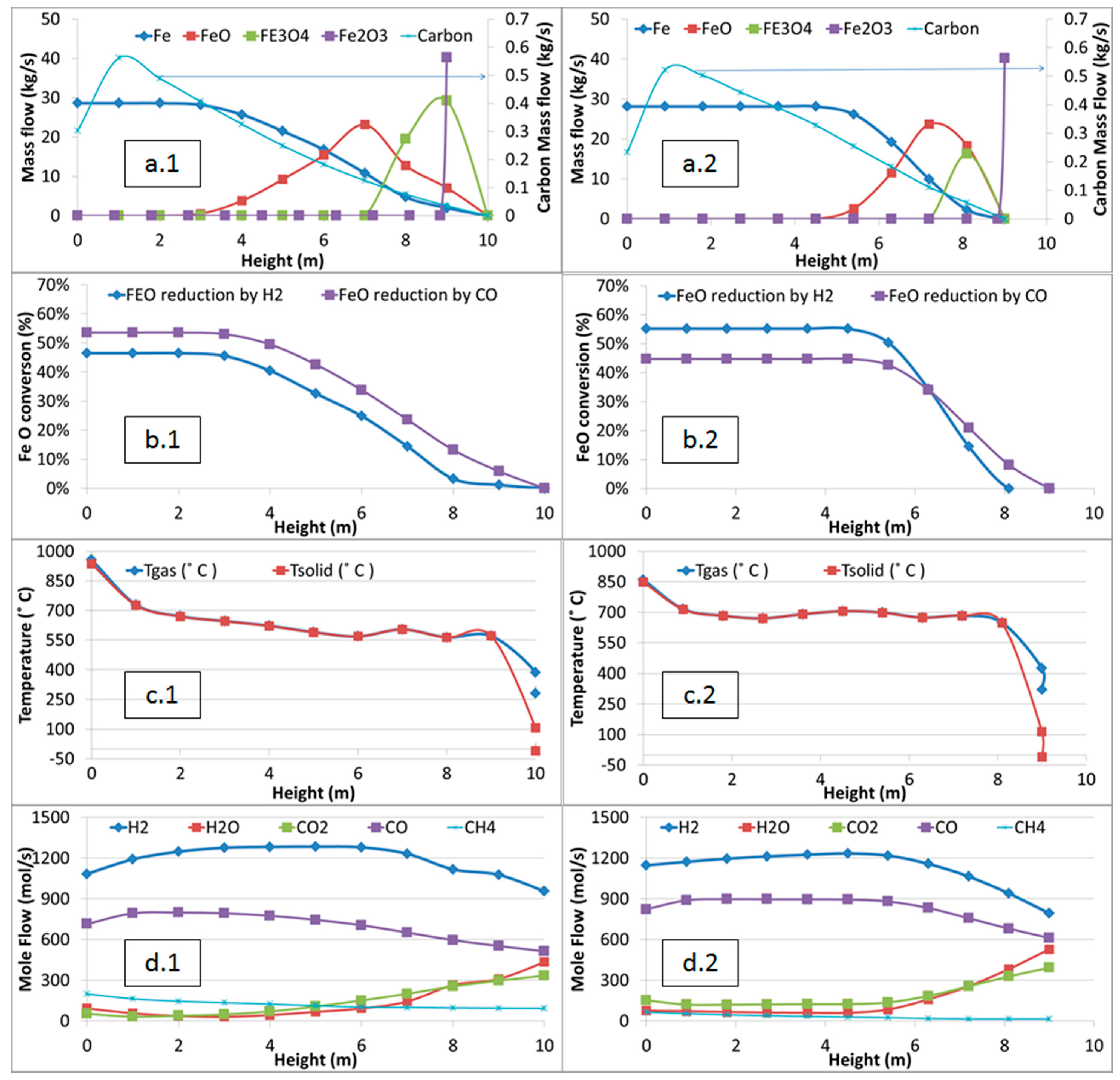
3.4. Comparison of Profiles in the Reduction Zone (Zone 1)

Changing the operating conditions of the process may induce changes of its behavior, especially for run 2, which considers modifications in the shaft geometry. As the reducing zone (Zone 1) was modeled through a 1D approach, it is possible to follow the evolution of different properties of the solids and gases along the shaft height. Figure 5 compares the evolution of the composition of the pellets (a), the conversion of FeO through its reduction by CO and H2 (b), the temperature of gas and solid phases (c) and the evolution of different gaseous components (d), for reference (1) and optimized (2) cases (run 2).
The stabilized temperature in the main part of the shaft reactor is significantly higher (about 50 °C) in run 2 than in the reference case. This phenomenon can be attributed to two factors: less methane reforming and a greater gas flow rate in the former case. Methane reforming is a highly endothermic reaction and the amount of methane entering the shaft is 3 times higher in the reference case than in run 2, which leads to a large drop in temperature while reforming occurs. Also, the higher heat content of the greater gas flow rate in run 2 helps maintain the temperature at a greater level.
The resulting higher temperature in run 2 leads to a better use of H2 for reduction, which is highlighted on the second line (b) graphs where more FeO is reduced by H2 than by CO. Considering that H2 has faster kinetics, the windows of presence of magnetite and wustite are drastically reduced in the shaft. The FeO reaction was the only shown because it is the slowest of the three reduction reactions.
Moreover, the steep drop in carbon content (line (a) graphs, right axis) towards the location of the reducing gas inlet (height zero) is linked to a higher Boudouard reaction rate caused by higher temperatures and CO2 input rates.
Concerning the various gaseous components, we can see that there is negligible methane in the shaft for the optimal case as compared to the original case. Also, the H2 flow rate does not see a steep increase from the reducing gas inlet (height 0) in the optimal case. This is mainly related to the absence of methane reactions. Also, H2O, CO and CO2 rates are higher in the optimal case than in the original one. In summary, the output has rather evenly partitioned components.

3.5. Comparison with Previous Literature Works

The present optimization indicated a set of prevalent tendencies that, in some cases, can be compared against previous findings. The lower optimized ( H 2 / CO ) ratios are in line with Parisi and Laborde [12], Nouri et al. [14] and Hamadeh [18]. The lower input temperature differs from a statement by Alamsari et al. [11] who suggested higher temperatures to get a higher carbon content in the output DRI. However, here, the carbon content in output DRI was not an objective nor a constraint in the studied optimization. The possibility of using wider and shorter shaft reactors was found to be contrary to [14] and [18]. This can be related to the definition of an objective function which called for shorter columns albeit guaranteeing good column performance. The higher recycling ratio found is in line with Ajbar et al. [16]. In comparison to the literature, the present study did not consider the effect of cooling gas flow rate and composition as did Shams et al. [15], nor that of the gas to the transition zone as in Ajbar et al. [16].
These differences observed can only be understood in light of the rarely considered interaction between the reformer and shaft reactor on one hand, and the choice of the objective function on the other hand, which was discussed in previous sections.
Considering the above information, in combination with the absence of published information regarding novel plant performances, it would be useful to confirm these findings in a thorough industrial search or in associated experimental effort.

3.6. Techno-Economic Remarks

Since the proposed optimization does not substantially modify the process configuration, it thus does not require consequential additional capital costs. However, the obtained results indicate a positive impact on the process operation cost through the reduction in the consumption of natural gas, which decreased by 18% between the optimal and reference cases. With this in mind, all things being equal, this optimization has thus the potential of simultaneously leading to a decrease in CO2 emissions and lower operation costs.

4. Conclusions

The present paper proposes new operating parameters for the direct reduction process of the MIDREX type in order to minimize its CO2 emissions. Those operating conditions were obtained by means of computer-aided optimization using Aspen Plus.
Results of two different optimization runs showed that the normalized carbon ratio (CO2/DRI) could be significantly reduced (about 15%) in comparison to the reference case, while keeping similar productivity, carbon content and metallization of the DRI.
Both optimized cases are characterized by a reducing gas of significantly lower temperature, higher CO and CO2 fractions and lower CH4 fraction. As a result, the optimal shaft reactor configuration showed smaller in-situ methane reforming rates, smaller in-reactor temperature drop, and finally a greater H2 reduction rate. At the process level, this was accompanied by a greater process gas recycling ratio for an equivalent reformer heat consumption. Somewhat paradoxically, lower CO2 emissions could be achieved by the use of higher CO and CO2 rate albeit with a greater gas recycling fraction.
In conclusion, this work shows the interest of computer-aided optimization to find new orientations for operating a process. The focus was set here on the minimization of the normalized carbon ratio through a mono-objective optimization algorithm. A next step could be to switch to multi-objective algorithms to consider simultaneously carbon emissions and productivity or costs. Other possible avenues worth exploring are the use of syngas of different origins, e.g., syngas from waste or biomass instead of reformed natural gas, as well as modified configurations of the whole DR process.

Author Contributions

Conceptualization, F.P., H.H. and R.B.; methodology: all; Fortran software: H.H.; Aspen Plus software: R.B. and O.M.; investigation: H.H. and R.B.; writing: R.B. and F.P.; supervision: F.P. and O.M.; Project Administration and Funding Acquisition: F.P. All authors have read and agreed to the published version of the manuscript.

Funding

This research was supported by the French State through two programs ‘Investment in the future’: (i) one operated by French Environment and Energy Management Agency (ADEME), ‘Valorization of CO2 in industry’, 2014-18, VALORCO, No. 1382C0245; the authors thank Nathalie Thybaud and Aïcha El Khamlichi, and the coordinator, Eric de Coninck; and (ii) one operated by the National Research Agency (ANR) and referenced by ANR-11-LABX-0008-01 (LabEx DAMAS).

Acknowledgments

The authors also express their thank to the staff of ArcelorMittal at Maizières-lès-Metz, France, and Contrecœur, Canada, for encouragements, information. and discussion, especially Salvatore Bertucci, Jean Borlée, Thibault Quatravaux, and Justin Farley.

Conflicts of Interest

The authors declare no conflict of interest.

References

  1. Quader, M.A.; Ahmed, S.; Ghazilla, R.A.R.; Ahmed, S.; Dahari, M. A comprehensive review on energy efficient CO2 breakthrough technologies for sustainable green iron and steel manufacturing. Renew. Sustain. Energy Rev. 2015, 50, 594–614. [Google Scholar] [CrossRef]
  2. van Ruijven, B.J.; van Vuuren, D.P.; Boskaljon, W.; Neelis, M.L.; Saygin, D.; Patel, M.K. Long-term model-based projections of energy use and CO2 emissions from the global steel and cement industries. Resour. Conserv. Recycl. 2016, 112, 15–36. [Google Scholar] [CrossRef] [Green Version]
  3. Song, J.; Jiang, Z.; Bao, C.; Xu, A. Comparison of Energy Consumption and CO2 Emission for Three Steel Production Routes-Integrated Steel Plant Equipped with Blast Furnace, Oxygen Blast Furnace or COREX. Metals 2019, 9, 364. [Google Scholar] [CrossRef] [Green Version]
  4. Xu, C.; Cang, D. A Brief Overview of Low CO2 Emission Technologies for Iron and Steel Making. J. Iron Steel Res. Int. 2010, 17, 1–7. [Google Scholar] [CrossRef]
  5. Müller, N.; Herz, G.; Reichelt, E.; Jahn, M. CO2 emission reduction potential in the steel industry by integration of a direct reduction process into existing steel mills. In Proceedings of the Challenges for Petrochemicals and Fuels: Integration of Value Chains and Energy Transition DGMK Conference, Berlin, Germany, 10–12 October 2018. [Google Scholar]
  6. Buergler, T.; Kofler, I. Direct reduction technology as a flexible tool to reduce the CO2 intensity of iron and steelmaking. BHM Berg-und Hüttenmännische Monatshefte 2017, 162, 14–19. [Google Scholar] [CrossRef]
  7. Huitu, K.; Helle, M.; Helle, H.; Kekkonen, M.; Saxen, H. Optimization of Midrex Direct Reduced Iron Use in Ore-Based Steelmaking. Steel Res. Int. 2015, 86, 456–465. [Google Scholar] [CrossRef]
  8. Midrex. World Direct Reduction Statistics. 2019. Available online: https://www.midrex.com/wp-content/uploads/Midrex_STATSbookprint_2018Final-1.pdf (accessed on 7 February 2020).
  9. Bechara, R.; Hamadeh, H.; Mirgaux, O.; Patisson, F. Optimization of the Iron Ore Direct Reduction Process through Multiscale Process Modeling. Materials 2018, 11, 1094. [Google Scholar] [CrossRef] [PubMed] [Green Version]
  10. Nogare, D.D.; Zugliano, A.; Primavera, A.; Melchiori, T.; Canu, P. Multiphysics simulation of a DRP shaft furnace. In Proceedings of the STEELSIM 2013 International Conference on Modelling and Simulation of Metallurgical Processes in Steelmaking, Ostrava, Czech Republic, 10–12 September 2013. [Google Scholar]
  11. Hamadeh, H.; Mirgaux, O.; Patisson, F. Detailed Modeling of the Direct Reduction of Iron Ore in a Shaft Furnace. Materials 2018, 11, 1865. [Google Scholar] [CrossRef] [PubMed] [Green Version]
  12. Parisi, D.; Laborde, M.A. Modelling of Counter Current Moving Bed Gas-Solid Reactor Used in Direct Reduction of Iron Ore. Chem. Eng. J. 2004, 104, 35–43. [Google Scholar] [CrossRef] [Green Version]
  13. Alamsari, B.; Torii, S.; Trianto, A.; Bindar, Y. Study of the Effect of Reduced Iron Temperature Rising on Total Carbon Formation in Iron Reactor Isobaric and Cooling Zone. Adv. Mech. Eng. 2010, 2, 192430. [Google Scholar] [CrossRef]
  14. Nouri, S.M.M.; Ebrahim, H.A.; Jamshidi, E. Simulation of direct reduction reactor by the grain model. Chem. Eng. J. 2011, 166, 704–709. [Google Scholar] [CrossRef]
  15. Shams, A.; Moazeni, F. Modeling and Simulation of the MIDREX Shaft Furnace: Reduction, Transition and Cooling Zones. JOM 2015, 67, 2681–2689. [Google Scholar] [CrossRef]
  16. Ajbar, A.; Alhumaizi, K.; Soliman, M.A.; Ali, E. Model-based energy analysis of an integrated Midrex-based iron/steel plant. Chem. Eng. Commun. 2014, 201, 1686–1704. [Google Scholar] [CrossRef]
  17. Ghadi, A.Z.; Valipour, M.S.; Biglari, M. CFD simulation of two-phase gas-particle flow in the Midrex shaft furnace: The effect of twin gas injection system on the performance of the reactor. Int. J. Hydrog. Energy 2017, 42, 103–118. [Google Scholar] [CrossRef]
  18. Hamadeh, H. Modélisation mathématique détaillée du procédé de réduction directe du minerai de fer. Ph.D. Thesis, Université de Lorraine, Nancy, France, 2017. Available online: https://tel.archives-ouvertes.fr/tel-01740462/ (accessed on 7 February 2020).
  19. Duarte, P.E.; Becerra, J. Reducing greenhouse gas emissions with Energiron non-selective carbon-free emissions scheme. Stahl und Eisen Zeitschrift fuer die Herstellung und Verarbeitung von Eisen und Stahl 2011, 131, S85–S86, S88–S90, S92–S94. [Google Scholar]
  20. Tanaka, H. Potential for CO2 Emissions Reduction in MIDREX Direct Reduction Process. In Proceedings of the IEA (International Energy Agency) Greenhouse Gas R&D workshop, Tokyo, Japan, 5–7 November 2013; Available online: https://ieaghg.org/2-uncategorised/392-iron-steel-workshop (accessed on 7 February 2020).
  21. Knop, K.; Ångström, S. Process for Production of Direct Reduced Iron. U.S. Patent No. 8,709,128, 29 April 2014. [Google Scholar]
  22. Ranzani da Costa, A.; Wagner, D.; Patisson, F. Modelling a new, low CO2 emissions, hydrogen steelmaking process. J. Clean. Prod. 2013, 46, 27–35. [Google Scholar] [CrossRef] [Green Version]
  23. Al-Malah, K.I.M. Aspen Plus: Chemical Engineering Applications; John Wiley & Sons: Hoboke, NJ, USA, 2016; ISBN 978-1-119-13123-6. [Google Scholar]
  24. Navid, A.; Khalilarya, S.; Abbasi, M. Diesel engine optimization with multi-objective performance characteristics by non-evolutionary Nelder-Mead algorithm: Sobol sequence and Latin hypercube sampling methods comparison in DoE process. Fuel 2018, 228, 349–367. [Google Scholar] [CrossRef]
  25. Ang, S.M.C.; Brett, D.J.L.; Fraga, E.S. A multi-objective optimisation model for a general polymer electrolyte membrane fuel cell system. J. Power Sources 2010, 195, 2754–2763. [Google Scholar] [CrossRef] [Green Version]
  26. Yildiz, A.R. A novel hybrid whale-Nelder-Mead algorithm for optimization of design and manufacturing problems. Int. J. Adv. Manuf. Technol. 2019, 105, 5091–5104. [Google Scholar] [CrossRef]
  27. Box, M.J. A new method of constrained optimization and a comparison with other methods. Comput. J. 1965, 8, 42–52. [Google Scholar] [CrossRef]
  28. Ölvander, J. Available online: https://complexmethod.readthedocs.io/en/latest/index.html (accessed on 7 February 2020).
Figure 1. Scheme of the MIDREX-type direct reduction process.
Metals 10 00367 g001
Figure 2. Modeled MIDREX process flow diagram, with its gas loop.
Metals 10 00367 g002
Figure 3. Dividing the shaft furnace into four zones (right hand side, as retained in the present Aspen Plus model) on the basis of the CFD simulation results (shown on the left-hand side with the example of the metallic iron mass fraction) given by [11].
Metals 10 00367 g003
Figure 4. Visual representation of the main results for reference case and run 2.
Metals 10 00367 g004
Figure 5. Evolution of the solid mass flow rates (a), FeO conversion from H2 and CO (b), temperatures (c) and gas molar flow rates (d) along Zone 1 height for the reference (left column .1) and optimized (right column .2) plant operation.
Metals 10 00367 g005
Table 1. Chemical reactions considered inside the shaft furnace.
Hematite reduction 3 Fe 2 O 3 + H 2 ( CO ) 2 Fe 3 O 4 + H 2 O ( CO 2 )
Magnetite reduction Fe 3 O 4 + 16 19 H 2   ( CO ) 60 19 Fe 0.95 O + 16 19 H 2 O ( CO 2 )
Wustite reduction Fe 0.95 O + H 2 ( CO ) 0.95 Fe + H 2 O ( CO 2 )
Water gas shift CO + H 2 O CO 2 + H 2
Steam methane reforming CH 4 + H 2 O 3 H 2 + CO
Methane cracking CH 4 C + 2 H 2
Boudouard reaction C + CO 2 2 CO
Table 2. Optimization variables.
Variable NumberVariable NameDescriptionOriginal Value/Range
1nCO,redComponent molar flow rates in the reducing gas inlet (kmol/s)0.7/[0.65–1.2]
2nH2,red1.08/[0.8–1.2]
3nH2O,red0.09/[0.02–0.3]
4nCO2,red0.05/[0.02–0.3]
5nCH4,red0.19/[0.02–0.25]
6Treducing gasReducing gas temperature (°C) 957/[850–970]
7mpelletPellet mass flow rate (kg/s) 45.54/[42.5–54]
8rreacRadius of the shaft furnace (m)2.75/[2.25–3.25]
9hreacHeight of shaft furnace *10/[6–14]
10dpPellet diameter (m)0.015/[0.01–0.016]
* Restricted to the reducing zone (Zones 1 and 2). The heights of the transition and cooling zones were kept constant.
Table 3. Values for key design parameters and results. The variables with a grey background are optimization variables.
VariablesReference Run 1Run 2
1 n CO , r e d   ( kmol / s ) 0.710.980.82
2 n H 2 , r e d   ( kmol / s ) 1.081.071.146
3 n H 2 O , r e d   ( kmol / s ) 0.09160.0960.075
4 n CO 2 , r e d   ( kmol / s ) 0.050.120.15
5 n CH 4 , r e d   ( kmol / s ) 0.19810.1670.064
6 T r e d u c i n g   g a s   ( ° C ) 957882860
7 m p e l l e t   ( kg / s ) 45.5445.5444.9
8 r r e a c (m)2.752.752.94
9 h r e a c (m)10109
10dp (m)0.0150.0150.0145
Objective
C n o r m a l (kg/kg)0.1230.1050.105
Results
m D R I   ( kg / s ) 33.52733.5332.90
Metallization (%)94.294.194.2
Carbon mass fraction in DRI0.02350.02370.02
( H 2 CO ) i n l e t 1.511.091.39
( CO + H 2 CO 2 + H 2 O ) i n l e t 129.48.7
Recycling ratio *0.630.770.73
n t o t , r e d   ( kmol / s ) 2.1782.4792.29
m t o t , r e d   ( kg / s ) 30.3540.4435.34
n CH 4 , r e f (kmol/s) 0.3390.2850.267
n CH 4 , b u r (kmol/s)00.0080.01
* Fraction of the top gas sent to the reformer, the rest being used in the burner.

