Thermal Fatigue Properties of H13 Hot-Work Tool Steels Processed by Selective Laser Melting


Abstract
1. Introduction
2. Materials and Methods
2.1. Materials and Post Treatment
2.2. Fatigue Testing
2.3. Materials Characterization
3. Results
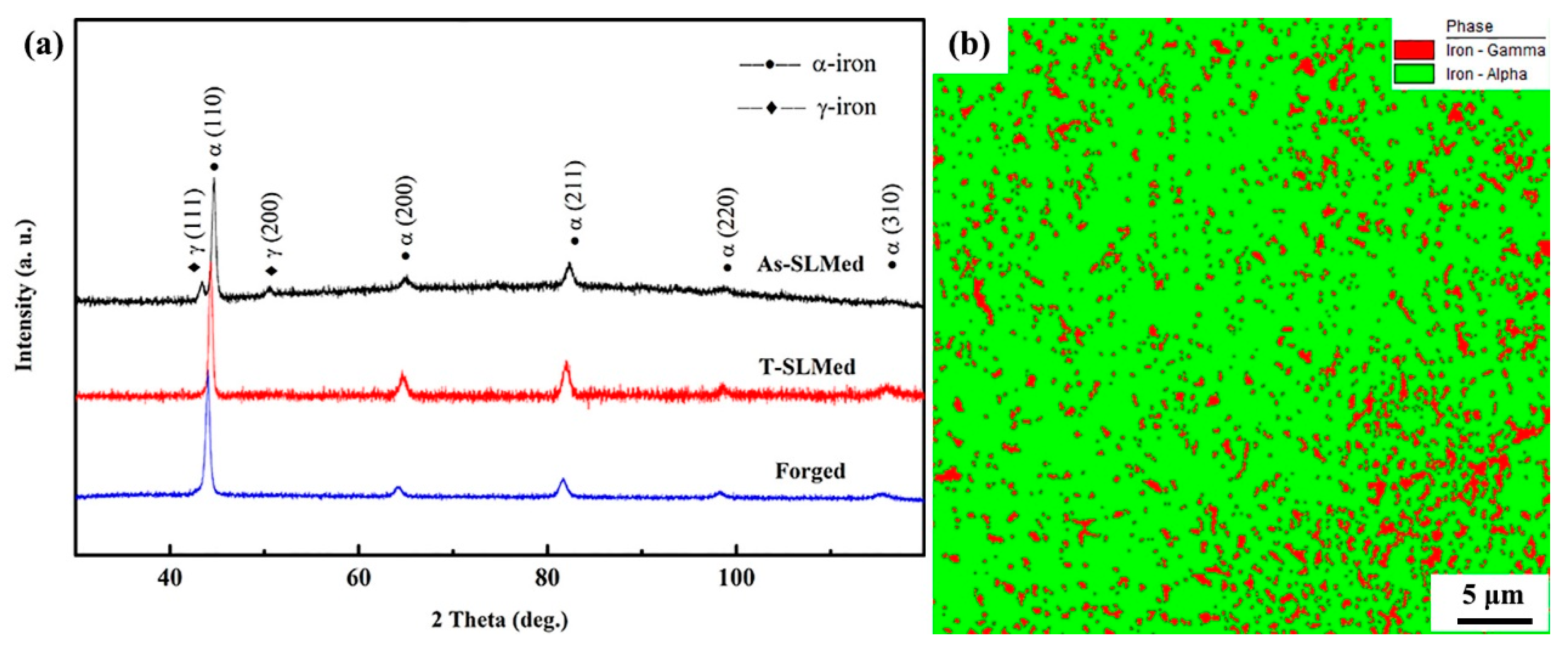
3.1. Phase Analysis
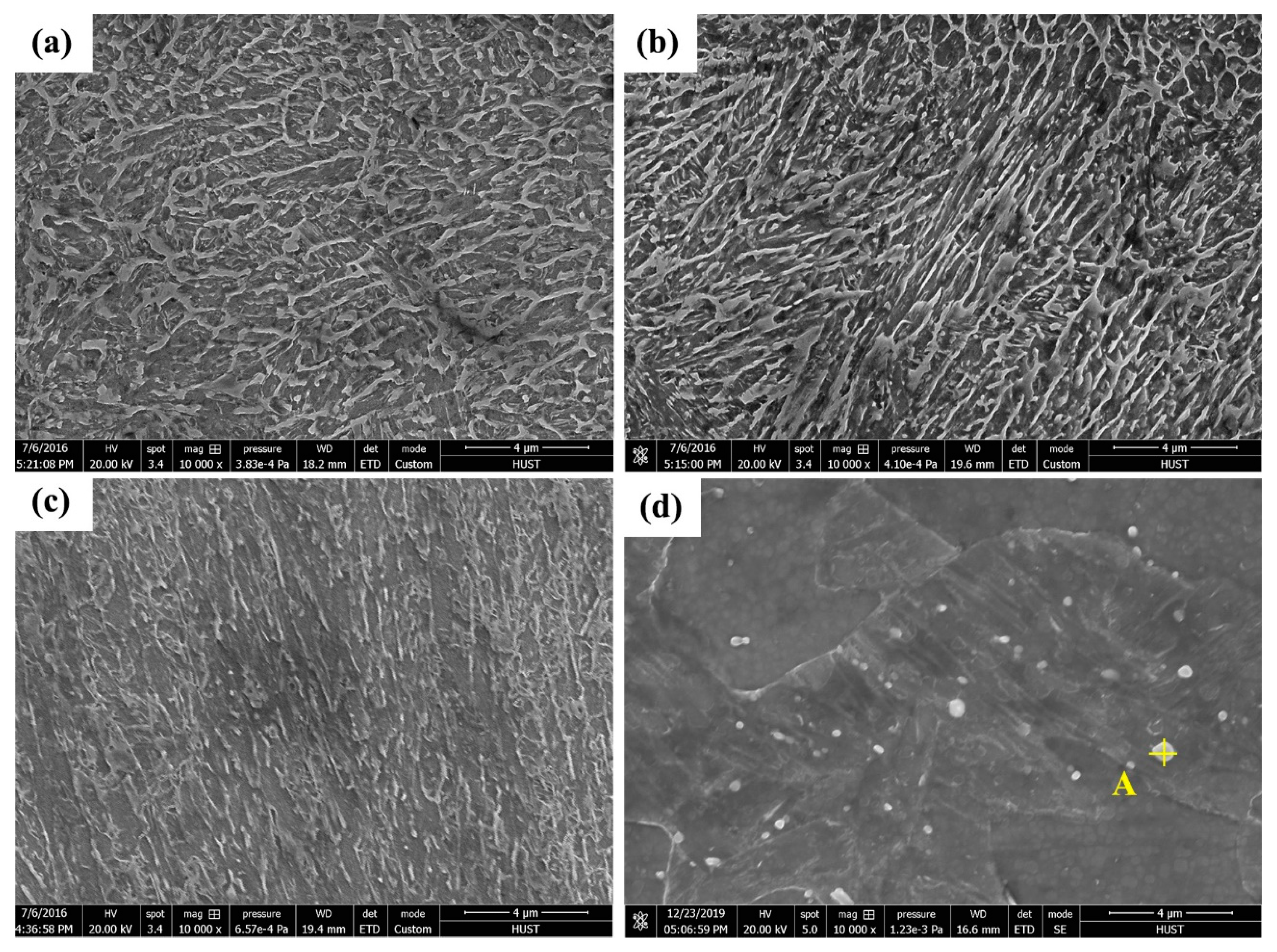
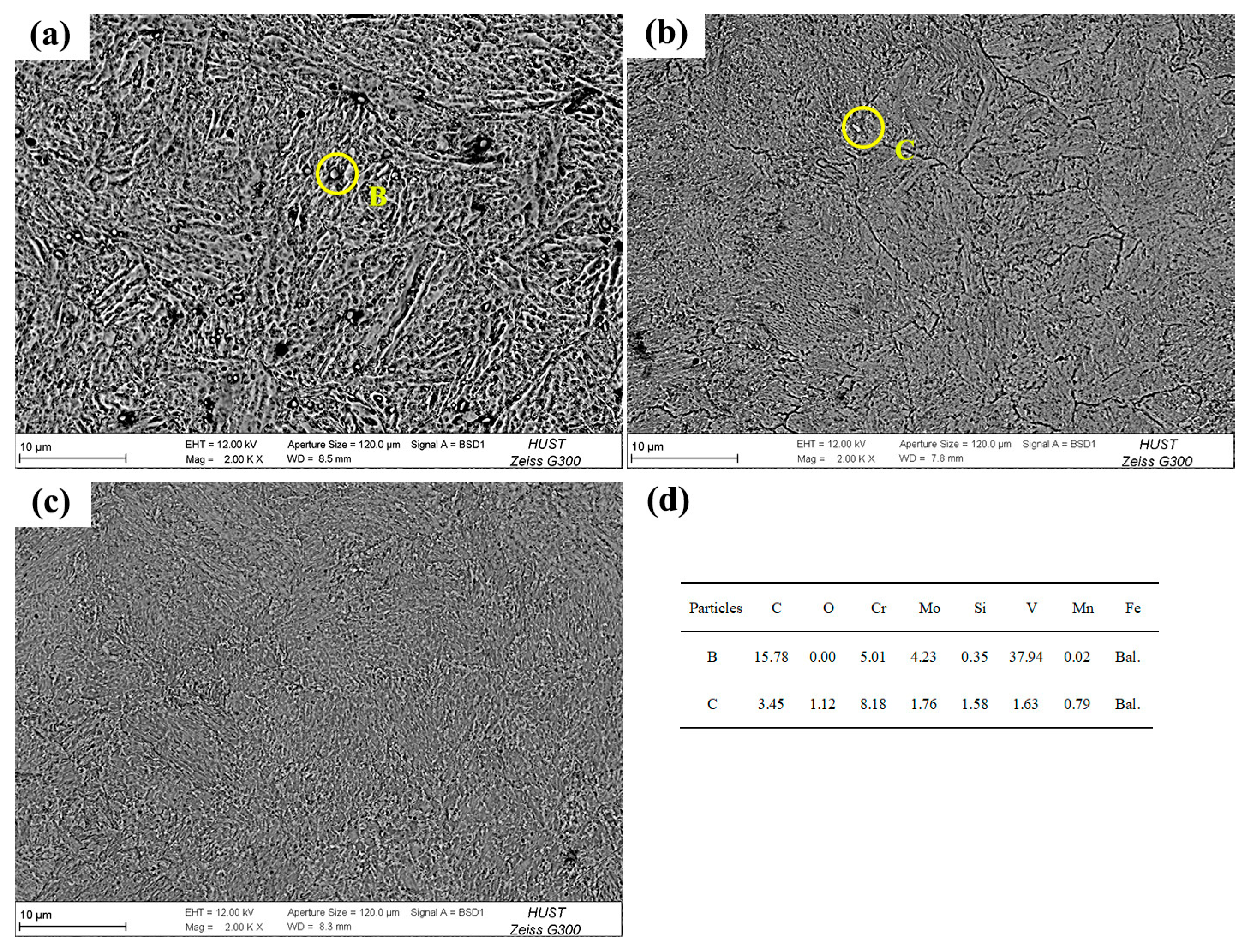
3.2. Microstructural Investigation
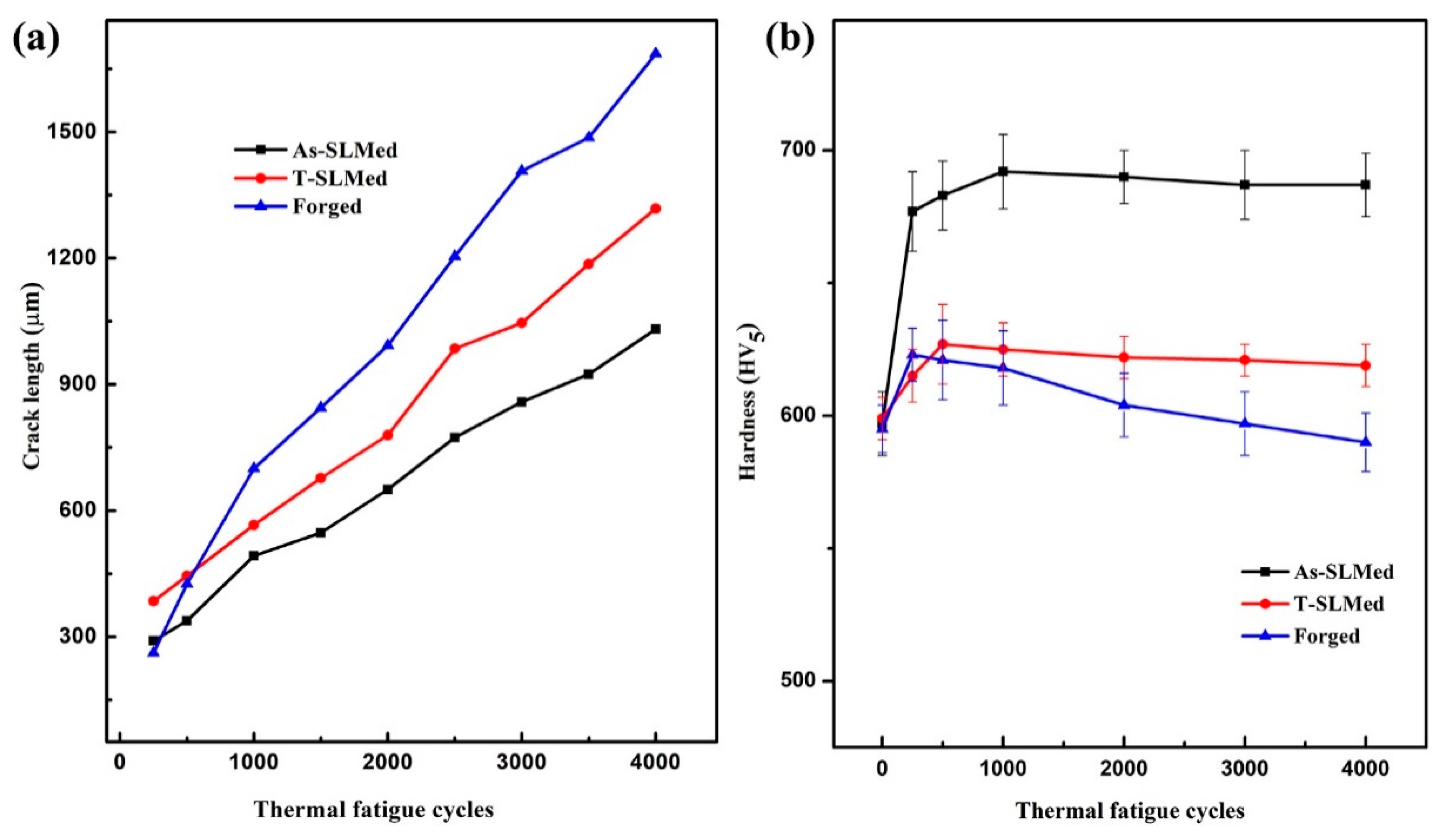
3.3. TF Properties
4. Discussion
4.1. Hardness Evolution during TF Testing
4.2. TF Cracking Characteristics
4.2.1. The Effect of Retained Austenite
4.2.2. The Effect of Block Size
4.2.3. The Effect of Coarse Laths
4.2.4. The Effect of Cell-Like Substructures
5. Conclusions
- (1)
- The As-SLMed H13 was composed of retained austenite and martensite along with a high density of dislocations. Cell-like substructures were homogeneously distributed in the matrix. The Forged H13 was composed of martensite and carbides.
- (2)
- The hardness of all the tested specimens was set at the level of approximately 597 HV5 before the tests. After TF tests, the As-SLMed and T-SLMed H13 showed secondary hardening properties, whereas the Forged H13 showed some softening behavior.
- (3)
- The As-SLMed H13 showed secondary hardening properties should be mainly attributed to the dissolution of the cell-like substructures into the matrix, the transformation of the retained and soft austenite into the hard martensite, and the precipitation of carbides during TF testing.
- (4)
- After TF tests, the As-SLMed H13 exhibited the shortest total crack length, while the Forged H13 exhibited the longest total crack length. These results proved that increased hardness can decelerate the crack propagation.
- (5)
- Microstructural investigation revealed that the increased amount of retained austenite, typical cell-like substructures, and refined grain size in the As-SLMed H13 were the main reasons for the increased TF resistance of the material compared to the Forged H13.
Data availability Statement
Author Contributions
Funding
Acknowledgments
Conflicts of Interest
References
- Bartlett, J.L.; Li, X. An overview of residual stresses in metal powder bed fusion. Addit. Manuf. 2019, 27, 131–149. [Google Scholar]
- Kruth, J.-P.; Vandenbroucke, B.; Vaerenbergh, V.J.; Mercelis, P. Benchmarking of different SLS/SLM processes as rapid manufacturing techniques. In Proceedings of the International Conference on Polymers and Moulds Innovations (PMI), Gent, Belgium, 20–23 April 2005. [Google Scholar]
- Kruth, J.-P.; Schueren, B.V.D.; Bonse, J.E.; Morren, B. Basic powder metallurgical aspects in selective metal powder sintering. CIRP Ann. 1996, 45, 183–186. [Google Scholar] [CrossRef]
- Wilson-Heid, A.E.; Qin, S.; Beese, A.M. Anisotropic multiaxial plasticity model for laser powder bed fusion additively manufactured Ti-6Al-4V. Mater. Sci. Eng. A 2018, 738, 90–97. [Google Scholar] [CrossRef]
- Hao, L.; Dadbakhsh, S. Materials and process aspects of selective laser melting of metals and metal matrix composites: A review. J. Chin. Laser 2009, 12, 3192–3203. [Google Scholar] [CrossRef]
- Meng, C.; Zhou, H.; Zhou, Y.; Gao, M.; Tong, X.; Cong, D.; Wang, C.; Chang, F.; Ren, L. Influence of different temperatures on the thermal fatigue behavior and thermal stability of hot-work tool steel processed by a biomimetic couple laser technique. Opt. Laser Technol. 2014, 57, 57–65. [Google Scholar] [CrossRef]
- Armillotta, A.; Baraggi, R.; Fasoli, S. SLM tooling for die casting with conformal cooling channels. Int. J. Adv. Manuf. Technol. 2014, 71, 573–583. [Google Scholar] [CrossRef]
- Eric, D. Design considerations of conformal cooling channels in injection mould tools design: An overview. J. Therm. Eng. 2015, 1, 627–635. [Google Scholar]
- Huber, F.; Bischof, C.; Hentschel, O.; Heberle, J.; Zettl, J.; Nagulin, K.Y.; Schmidt, M. Laser beam melting and heat-treatment of 1.2343 (AISI H11) tool steel-microstructure and mechanical properties. Mater. Sci. Eng. A 2019, 742, 109–115. [Google Scholar] [CrossRef]
- Petrovic, V.; Vicente Haro Gonzalez, J.; Jorda Ferrando, O.; Delgado Gordillo, J.; Ramon Blasco Puchades, J.; Portoles Grinan, L. Additive layered manufacturing: Sectors of industrial application shown through case studies. Int. J. Prod. Res. 2011, 49, 1061–1079. [Google Scholar] [CrossRef]
- Hölker, R.; Jäger, A.; Khalifa, N.B.; Tekkaya, A.E. Controlling heat balance in hot aluminum extrusion by additive manufactured extrusion dies with conformal cooling channels. Int. J. Precis. Eng. Manuf. 2013, 14, 1487–1493. [Google Scholar] [CrossRef]
- Sander, J.; Hufenbach, J.; Giebeler, L.; Wendrock, H.; Kühn, U.; Eckert, J. Microstructure and properties of FeCrMoVC tool steel produced by selective laser melting. Mater. Des. 2016, 89, 335–341. [Google Scholar] [CrossRef]
- Wang, M.; Li, W.; Wu, Y.; Li, S.; Cai, C.; Wen, S.; Wei, Q.; Shi, Y.; Ye, F.; Chen, Z. High-temperature properties and microstructural stability of the AISI H13 hot-work tool steel processed by selective laser melting. Metall. Mater. Trans. B 2019, 50, 531–542. [Google Scholar] [CrossRef]
- Deirmina, F.; Peghini, N.; AlMangour, B.; Grzesiak, D.; Pellizzari, M. Heat treatment and properties of a hot work tool steel fabricated by additive manufacturing. Mater. Sci. Eng. A 2019, 753, 109–121. [Google Scholar] [CrossRef]
- Mertens, R.; Vrancken, B.; Holmstock, N.; Kinds, Y.; Kruth, J.-P.; Van Humbeeck, J. Influence of powder bed preheating on microstructure and mechanical properties of H13 tool steel SLM parts. Phys. Procedia 2016, 83, 882–890. [Google Scholar] [CrossRef]
- Dörfert, R.; Zhang, J.; Clausen, B.; Freiße, H.; Schumacher, J.; Vollertsen, F. Comparison of the fatigue strength between additively and conventionally fabricated tool steel 1.2344. Addit. Manuf. 2019, 27, 217–223. [Google Scholar] [CrossRef]
- Laakso, P.; Riipinen, T.; Laukkanen, A.; Andersson, T.; Jokinen, A.; Revuelta, A.; Ruusuvuori, K. Optimization and simulation of SLM process for high density H13 tool steel parts. Phys. Procedia 2016, 83, 26–35. [Google Scholar] [CrossRef]
- Ren, B.; Lu, D.; Zhou, R.; Li, Z.; Guan, J. Preparation and mechanical properties of selective laser melted H13 steel. J. Mater. Res. 2019, 34, 1415–1425. [Google Scholar] [CrossRef]
- Kurzynowski, T.; Stopyra, W.; Gruber, K.; Ziolkowski, G.; Kuznicka, B.; Chlebus, E. Effect of scanning and support strategies on relative density of SLM-ed H13 steel in relation to specimen size. Materials 2019, 12, 239. [Google Scholar] [CrossRef]
- Holzweissig, M.J.; Taube, A.; Brenne, F.; Schaper, M.; Niendorf, T. Microstructural characterization and mechanical performance of hot work tool steel processed by selective laser melting. metall. Mater. Trans. B 2015, 46, 545–549. [Google Scholar] [CrossRef]
- Åsberg, M.; Fredriksson, G.; Hatami, S.; Fredriksson, W.; Krakhmalev, P. Influence of post treatment on microstructure, porosity and mechanical properties of additive manufactured H13 tool steel. Mater. Sci. Eng. A 2019, 742, 584–589. [Google Scholar] [CrossRef]
- Pinkerton, A.J.; Li, L. Direct additive laser manufacturing using gas- and water-atomised H13 tool steel powders. Int. J. Adv. Manuf. Technol. 2004, 25, 471–479. [Google Scholar] [CrossRef]
- Chen, C.; Wang, Y.; Ou, H.; Lin, Y.-J. Energy-based approach to thermal fatigue life of tool steels for die casting dies. Int. J. Fatigue 2016, 92, 166–178. [Google Scholar] [CrossRef]
- Starling, C.M.D.; Branco, J.R.T. Thermal fatigue of hot work tool steel with hard coatings. Thin Solid Films 1997, 308, 436–442. [Google Scholar] [CrossRef]
- Jia, Z.-X.; Liu, Y.-W.; Li, J.-Q.; Liu, L.-J.; Li, H.-L. Crack growth behavior at thermal fatigue of H13 tool steel processed by laser surface melting. Int. J. Fatigue 2015, 78, 61–71. [Google Scholar] [CrossRef]
- Mellouli, D.; Haddar, N.; Köster, A.; Ayedi, H.F. Hardness effect on thermal fatigue damage of hot-working tool steel. Eng. Fail. Anal. 2014, 45, 85–95. [Google Scholar] [CrossRef]
- Persson, A.; Hogmark, S.; Bergström, J. Thermal fatigue cracking of surface engineered hot work tool steels. Surf. Coat. Technol. 2005, 191, 216–227. [Google Scholar] [CrossRef]
- Tong, X.; Dai, M.-J.; Zhang, Z.-H. Thermal fatigue resistance of H13 steel treated by selective laser surface melting and CrNi alloying. Appl. Surf. Sci. 2013, 271, 373–380. [Google Scholar] [CrossRef]
- Yan, J.J.; Zheng, D.L.; Li, H.X.; Jia, X.; Sun, J.F.; Li, Y.L.; Qian, M.; Yan, M. Selective laser melting of H13: Microstructure and residual stress. J. Mater. Sci. 2017, 52, 12476–12485. [Google Scholar] [CrossRef]
- Sjöström, J.; Bergström, J. Thermal fatigue testing of chromium martensitic hot-work tool steel after different austenitizing treatments. J. Mater. Process. Technol. 2004, 153, 1089–1096. [Google Scholar] [CrossRef]
- Delagnes, D.; Lamesle, P.; Mathon, M.H.; Mebarki, N.; Levaillant, C. Influence of silicon content on the precipitation of secondary carbides and fatigue properties of a 5% Cr tempered martensitic steel. Mater. Sci. Eng. A 2005, 394, 435–444. [Google Scholar] [CrossRef]
- ASM International Handbook Committee. ASM Handbook. Volume 1: Properties and Selection: Irons, Steels, and High. Performance Alloys; ASM International: Novelty, OH, USA, 1996. [Google Scholar]
- Gwon, H.; Kim, J.-K.; Shin, S.; Cho, L.; De Cooman, B.C. The effect of vanadium micro-alloying on the microstructure and the tensile behavior of TWIP steel. Mater. Sci. Eng. A 2017, 696, 416–428. [Google Scholar] [CrossRef]
- Bhadeshia, H.K.D.H.; Honeycombe, R. Steels: Microstructure and Properties, 3rd ed.; Butterworth-Heinemann: Oxford, UK, 2006. [Google Scholar]
- Afkhami, S.; Dabiri, M.; Alavi, S.H.; Björk, T.; Salminen, A. Fatigue characteristics of steels manufactured by selective laser melting. Int. J. Fatigue 2019, 122, 72–83. [Google Scholar] [CrossRef]
- Henry, B.W.; Bragg, W.L. The reflection of X.-rays by crystals, P. Roy. Soc. Lond. Ser. A 1913, 88, 428–438. [Google Scholar]
- Dilip, J.J.S.; Ram, G.D.J.; Starr, T.L.; Stucker, B. Selective laser melting of HY100 steel: Process parameters, microstructure and mechanical properties. Addit. Manuf. 2017, 13, 49–60. [Google Scholar] [CrossRef]
- Saeidi, K.; Gao, X.; Lofaj, F.; Kvetková, L.; Shen, Z.J. Transformation of austenite to duplex austenite-ferrite assembly in annealed stainless steel 316L consolidated by laser melting. J. Alloys Comp. 2015, 633, 463–469. [Google Scholar] [CrossRef]
- ASM International Handbook Committee. ASM Handbook. Volume 4: Heat Treating; ASM International: Novelty, OH, USA, 1990. [Google Scholar]
- Kitahara, H.; Ueji, R.; Tsuji, N.; Minamino, Y. Crystallographic features of lath martensite in low-carbon steel. Acta Mater. 2006, 54, 1279–1288. [Google Scholar] [CrossRef]
- Berecz, T.; Jenei, P.; Csóré, A.; Lábár, J.; Gubicza, J.; Szabó, P.J. Determination of dislocation density by electron backscatter diffraction and X-ray line profile analysis in ferrous lath martensite. Mater. Charact. 2016, 113, 117–124. [Google Scholar] [CrossRef]
- Zhang, P.; Li, S.X.; Zhang, Z.F. General relationship between strength and hardness. Mater. Sci. Eng. A 2011, 529, 62–73. [Google Scholar] [CrossRef]
- Medvedeva, A.; Bergström, J.; Gunnarsson, S.; Andersson, J. High-temperature properties and microstructural stability of hot-work tool steels. Mater. Sci. Eng. A 2009, 523, 39–46. [Google Scholar] [CrossRef]
- Klobčar, D.; Tušek, J.; Taljat, B. Thermal fatigue of materials for die-casting tooling. Mater. Sci. Eng. A 2008, 472, 198–207. [Google Scholar] [CrossRef]
- Hao, K.; Gong, M.; Pi, Y.; Zhang, C.; Gao, M.; Zeng, X. Effect of Ni content on rolling toughness of laser-arc hybrid welded martensitic stainless steel. J. Mater. Process. Technol. 2018, 251, 127–137. [Google Scholar] [CrossRef]
- Koyama, M.; Zhang, Z.; Wang, M.; Ponge, D.; Paabe, D.; Tsuzaki, K.; Noguchi, H.; Tasan, C.C. Bone-like crack resistance in hierarchical metastable nanolaminate steels. Science 2017, 355, 1055–1057. [Google Scholar] [CrossRef] [PubMed]
- Li, S.; Zhu, G.; Kang, Y. Effect of substructure on mechanical properties and fracture behavior of lath martensite in 0.1C–1.1Si–1.7Mn steel. J. Alloys Comp. 2016, 675, 104–115. [Google Scholar] [CrossRef]
- Stonesifer, F.R.; Armstrong, R.W. Effect of Prior Austenite Grain Size on the Fracture Toughness Properties of A533 Steel; ICF4: Waterloo, Canada, 1977. [Google Scholar]
- Morsdorf, L.; Jeannin, O.; Barbier, D.; Mitsuhara, M.; Raabe, D.; Tasan, C.C. Multiple mechanisms of lath martensite plasticity. Acta Mater. 2016, 121, 202–214. [Google Scholar] [CrossRef]
- ASM International Handbook Committee. ASM Handbook. Volume 19: Fatigue and Fracture; ASM International: Novelty, OH, USA, 1996. [Google Scholar]
- AlMangour, B.; Grzesiak, D.; Yang, J.-M. Nanocrystalline TiC-reinforced H13 steel matrix nanocomposites fabricated by selective laser melting. Mater. Des. 2016, 96, 150–161. [Google Scholar] [CrossRef]
- Hawryluk, M. Review of selected methods of increasing the life of forging tools in hot die forging processes. Arch. Civ. Mech. Eng. 2016, 16, 845–866. [Google Scholar] [CrossRef]


| Material Type | C | Cr | Mo | Si | V | Mn | Fe |
|---|---|---|---|---|---|---|---|
| SLMed H13 | 0.37 | 5.05 | 1.32 | 1.11 | 1.07 | 0.49 | Bal. |
| Forged H13 | 0.39 | 4.80 | 2.4 | 0.24 | 0.55 | 0.50 | Bal. |
| Tolerance (±) | 0.005 | 0.035 | 0.024 | 0.020 | 0.020 | 0.015 |
| Material Type | Density (g/cm3) | Hardness (HV5) | Heat Treatment Methods |
|---|---|---|---|
| As-SLMed | 7.754 ± 0.0037 | 597 ± 12 | As-built condition |
| T-SLMed | 7.754 ± 0.0037 | 599 ± 8 | Tempering at 500 °C/2 h and then tempering at 600 °C/2 h |
| Forged | 7.760 ± 0.0063 | 595 ± 9 | Solution treatment at 1020 °C/30 min; oil quenching; double tempering at 510 °C/2 h; air cooling |
© 2020 by the authors. Licensee MDPI, Basel, Switzerland. This article is an open access article distributed under the terms and conditions of the Creative Commons Attribution (CC BY) license (http://creativecommons.org/licenses/by/4.0/).
Share and Cite
Wang, M.; Wu, Y.; Wei, Q.; Shi, Y. Thermal Fatigue Properties of H13 Hot-Work Tool Steels Processed by Selective Laser Melting. Metals 2020, 10, 116. https://doi.org/10.3390/met10010116
Wang M, Wu Y, Wei Q, Shi Y. Thermal Fatigue Properties of H13 Hot-Work Tool Steels Processed by Selective Laser Melting. Metals. 2020; 10(1):116. https://doi.org/10.3390/met10010116
Chicago/Turabian StyleWang, Mei, Yan Wu, Qingsong Wei, and Yusheng Shi. 2020. "Thermal Fatigue Properties of H13 Hot-Work Tool Steels Processed by Selective Laser Melting" Metals 10, no. 1: 116. https://doi.org/10.3390/met10010116
APA StyleWang, M., Wu, Y., Wei, Q., & Shi, Y. (2020). Thermal Fatigue Properties of H13 Hot-Work Tool Steels Processed by Selective Laser Melting. Metals, 10(1), 116. https://doi.org/10.3390/met10010116